doi: 10.11648/j.wcmc.20140202.11
Optimal load balancing algorithm for multi-cell LTE
networks
Jian Li, Yifeng He, Yun Tie, Ling Guan
Department of Electrical and Computer Engineering, Ryerson University, Toronto, Canada
Email address:
[email protected] (J. Li), [email protected] (Y. He), [email protected] (Y. Tie), [email protected] (L. Guan)
To cite this article:
Jian Li, Yifeng He, Yun Tie, Ling Guan. Optimal Load Balancing Algorithm for Multi-Cell LTE Networks. International Journal of Wireless Communications and Mobile Computing. Vol. 2, No. 2, 2014, pp. 23-29. doi: 10.11648/j.wcmc.20140202.11
Abstract:
Long Term Evolution (LTE) is a promising option for the 4th generation communications because of its higher data rates, lower latency and larger coverage. However, in a multi-cell LTE network, the network performance may be deteriorated by load imbalance. The unbalanced load among multiple cells leads to a higher delay and a higher packet drop rate in the over-loaded cell, or an underutilization of resources in the under-loaded cell. In order to solve this problem, we propose a practical load balancing algorithm to find the optimal handover operations between the overloaded cell and possible target cells. The simulation results demonstrate that the proposed algorithm can reduce network overload and increase the network bandwidth efficiency.Keywords: Smart Grid, LTE, Load Balancing, Resource Allocation
1. Introduction
The 3rdGeneration Partnership Project (3GPP) Long Term Evolution (LTE) is a promising option for the 4th generation communications because of its higher data rate, lower latency and larger coverage. The LTE Release 9 shows that LTE provides up to 300Mbpsdownload rate and 75Mbps upload rate [1]. The specification also defines Orthogonal Frequency Division Multiple Access(OFDMA) as the access technique for the downlink and Single Carrier FDMA (SC-FDMA) for the uplink [2]. OFDMA shows robustness against multi-path fading, high spectral efficiency, and bandwidth scalability, and SC-FDMA enables users to save energy. The additional crucial technique applied in LTE is Multiple-Input-Multiple-Output (MIMO) that uses multiple transmitters and receivers to achieve a higher bit rate and an improved coverage [3].
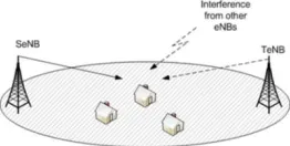
Figure 1. LTE network model where the user can receive multiple signals
from different eNBs.
In a multi-cell LTE network, it is critical to balance the load among the neighboring cells. The LTE network performance maybe deteriorated by load imbalance among multiple cells. Figure 1 shows a network consists of multiple cells, each of which is controlled by the LTE base station, named Evolved Node B(eNB) in LTE system. Each user can receive the signal from more than one eNBs, including one serving eNB (SeNB) and one or multiple target eNBs (TeNBs). The SeNB represents the eNB which is serving the user, while the TeNBs represent the eNBs which can reach the users but are not serving the users. An imbalanced multi-cell LTE network will suffer from an increased delay, a decreased network throughput, and even packet drops. Therefore, the LTE multi-cell load balancing problem needs to be considered carefully.
The load balancing algorithm in the wireless cellular networks aims to find the optimal handover operations between the overloaded cell and possible target cells. The users in the overloaded cell are handed over to the under-loaded cells in order to improve the overall network performance in terms of the latency and throughput. However, it is quite challenging to appropriately distribute the load among multiple cells for improved network performance.
among the neighbouring cells. The proposed scheme can select a proper SeNB among the multiple TeNBs for each user based on the load difference and the Signal to Interference plus Noise Ratio (SINR). We conducted the performance evaluation in the network simulator OPNET [4]. The simulation results demonstrated that the proposed scheme can get a lower end-to-end delay.
This paper is organized as follows. We describe the related work in Section 2. In Section 3, we present the network models. In Section 4, we present the problem formulation and the proposed load-balancing algorithm. The experiment results are provided in Section 5 and the conclusions are drawn in Section 6.
2. Related Work
LTE load balancing problem has been investigated in the literature. Viering et al. presented a mathematical framework for quantitative study of self-optimizing wireless networks for LTE system, in which a self-optimizing network algorithm was proposed to adjust the cell-specific handover thresholds for load balancing [5]. Lobinger et al. proposed a handover off set based load balancing algorithm using the parameter “cell specific offset” to force users to handover from the overload eNB to the target eNB [6]. The main goal of the proposed algorithm is to find the optimalhand over offset that allows the maximum number of users to change cell without any admission rejection at the target eNB [6]. A directional cell breathing based reactive congestion control algorithm was proposed in [7], where the coverage area of a cell can be dynamically extended towards a nearby loaded cell when it is under-loaded, or shrunk towards the cell center when it is over-loaded.
3. Network Models
In this section, we describe the channel model and several network parameters including resource block utilization ratio and average resource block utilization ratio.
3.1. Channel Model
We assume that each cell knows the instantaneous signal strength sending from the users through the control signals, such as Channel State Information (CSI). We divide the time into time slots with equal length . We assume that the received SINR at eNB keeps unchanged during a time slot. The average received SINR at the base station of cell k from user i at time slot is given by [8]
, ( ) =
( )/ ,( )
∑≠ ( )∙ / , ( )+ , (1)
where ( ) represents the transmit power of the user at time slot , , ( )represents the path loss from the user to the base station taking into account the distance between them, and represents the power of Additive White Gaussian Noise (AWGN). represents the resource
blocks (RBs) utilization ratio of cell , which is described in Section 3.2.
The data rate , ( ) at time slot t can be calculated using Shannon-Hartley theorem, which is given by[9]
, ( ) = , ( ) log (1 + , ( )), (2)
where represents the total bandwidth for the eNB, is the total number of RBs for the eNB, and , ( ) represents the number of RBs allocated to user by cell at time slot , which can be determined using the LTE scheduling algorithm.
Therefore, the data rate depends on the channel condition between the users and the eNB. In other words, to send the same amount of the traffic, the user with a better channel condition will consume a less number of the resource blocks than the user with a worse channel condition.
3.2. Network Parameters
In order to investigate the different load distributions of different eNBs, we define the network parameters as follows. We use RB utilization ratio ( ) to denote the ratio between the number of the allocated RBs and the total number of the RBs in cell k at time slot t. A larger ( )
indicates a higher percentage of RB utilization in cell k, and thus a higher level of load in cell k. Assuming that all cells have the same number of RBs, denoted by . Then, ( )
for cell at time slot can be written as [10]
( ) =∑#∈'"#,$(%)
, (3)
where represents the set of users in the whole network.
, ( ) is the number of RBs that cell allocates to user at time slot which can be determined by the LTE scheduling algorithm. We assume that the length of the time slot is much larger than the subframe duration (e.g., 1 ms).
The average RB utilization ratio of the whole network at time slot is given by
( ) = (
|*|∑ ∈* ( ), (4)
where + is the set of the cells in the network, and |+|
represents the number of the cells in the set +.
Handovers will be performed in case of overload. However, during the handover operation, the total load should not exceed the capacity of the eNB. We introduce a parameter ,( ) to indicate the load balancing level of the LTE network. The level of load balancing can be evaluated by the fairness index [11], which is given by
,( ) =
[∑$∈/.$(%)]1|*| [∑$∈/.$(%)1]
,
(5)
where the value of load balancing index ,( ) is in the range [1/N, 1]. A larger ,( ) indicates a more balanced load distribution among cells, and vice versa. Particularly,
4. Load Balancing Algorithm
4.1. Problem Formulation
In this section, we formulate the optimization problem for load balancing in the LTE network. On the one hand, we want to use a minimal resource to send all traffic in the network, which means that we want to minimize the average RB utilization ratio ( ). On the other hand, we want to evenly utilize the RBs among cells, which means that we want to maximize the load balancing level ,( ). However,
( ) and ,( ) depend on each other. Reducing ( ) may lead to load unbalancing, while increasing ,( ) may cause a higher consumption of RBs. Considering the trade-off between the average RB utilization ratio ( ) and the load balancing level ,( ) , we introduce an aggregation
parameterz, which is defined as
2 = 3 ( ) − (1 − 3),( ), (6)
where 3 is a weight representing the trade-off between the RB utilization and the load balancing level. If 3 is set to 1, the RB utilization will be the objective. On the contrary, if3
is equal to 0, the load balancing level will be the objective. When 3 is between 0 and 1, the objective is the compromised value taking into account both RB utilization and load balance.
Therefore, the optimization problem is mathematically formulated as follows:
Minimize{ "#,$} 3 ( ) − (1 − 3) ,( ) (7a)
Subject to:
∑∈= , ( ) , ( )≤ , ∀ ∈ +, (7b)
∑ ∈* , ( ) = 1, ∀ ∈ , ∀ ∈ +, (7c)
, ( ) ≥ %A, ∀ ∈ , ∀ ∈ +. (7d)
The objective function (7a) represents the combination of the RB utilization and the load balancing level with the weight parameter 3 (0 < 3 < 1). Constraint (7b) shows that the number of resource blocks occupied by all users in a cell should not exceed the total number of resource blocks in the cell. Constraint (7c) specifies that each user can be served by only one eNB. Constraint (7d) represents that a user’s
, ( ) should not be lower than the SINR threshold
%A in order to ensure acceptable data communications.
4.2. Practical Load-Balancing Algorithm
The optimization problem (7) is an integer programming. If we use exhaust search to find the optimal solution, it is not suitable for delay-sensitive applications because the processing time will be unacceptable. In this section, we propose a practical load-balancing algorithm which provides a sub-optimal but much more efficient solution to the optimization problem (7). The principle of the proposed algorithm is that the user always chooses the eNB with the
highest z value as its serving eNB.
The proposed practical load balancing algorithmis executed at each SeNB. The SeNB first finds the set of the users, denoted by S, that are served by it, and then sorts the users in the set S in an ascending order based on their SINR values. For each user in the set S, SeNB will find a better TeNB if available, and hand over the user to the chosen TeNB. The process of finding the better TeNB is as follows. First, the SeNB finds the set of the target TeNBs, denoted by W, for the current user. Then, for each TeNB in the set W, the SeNB calculates the number of required resource blocks if the user is handed over to the TeNB, and compares the current value 2EF with the 2 value of the TeNB 2GF . If the difference between2EF and 2GF is larger than a threshold %A, the user will be handed over from the current SeNB to the TeNB. The same procedure repeats until all users in the set S have been processed by the SeNB. The proposed practical load balancing algorithm is presented in Algorithm 1as follows.
Algorithm 1: the proposed practical load balancing algorithm executed at a SeNB
1: Find the set of users, denoted by S, that are currently served by the SeNB.
2: Sort the users in the set S in an ascending order based on their SINR values.
3: for each user in the set Sdo 4: Calculate 2EF value;
5: Find the set of TeNBs, denoted by H;
6: Collect measurements (e.g., CSI) from the user to each TeNB in the set H;
7: Obtain the number of the available resource blocks at each TeNB in the set H;
8: for each TeNB in the set Hdo
9: if ≥ %Athen
10: Calculate the number of required resource blocks after the handover; 11: Calculate the 2GF value;
12: if2EF − 2GF > %Athen
13:Perform handover from SeNB to TeNB; 14: break;
15: end if 16: end if 17: end for 18: end for
The proposed practical load balancing algorithmis a sub-optimal solution to the optimization problem (7). The advantage of the proposed algorithm is that it can find the near-minimum objective at a much faster speed than the
exhaust search approach. The difficulty of finding the
If a handover is performed as long as the users’ z value of TeNB 2GF is smaller than that of SeNB 2EF , it may lead to hand over ping-pong effect[12], which means that a user switches its SeNB frequently and cannot reach a stable state. In order to prevent the handover ping-pong effect, we introduce an threshold value %A in the proposed algorithm. Only when 2EF − 2GF > %A, a handover is triggered. The threshold %A should be chosen carefully. A smaller %A may still cause the ping-pong effect, while a larger %A would make the proposed algorithm perform worse.
5. Simulations
In this section, we perform simulations to evaluate the network performance of the proposed algorithm in terms of the algorithm efficiency and load balancing efficiency.
OPNET Modeler [13] is a network simulation tool. It provides a comprehensive environment for modeling and simulation of deployed wired and wireless networks. OPNET Modeler enables users to create customized models and to simulate various network scenarios. The wireless module is used to create models for wireless scenarios such as Wi-Fi and LTE. The Modeler is object-oriented and employs a hierarchical approach to model communications networks. It provides graphical user interfaces known as editors to capture the specifications of deployed networks, equipment, and protocols.
5.1. Simulation Setting
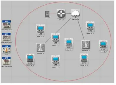
Figure 2. Network topology in the simulation.
We simulate a city-scale LTE network of 5km × 5km. The network topology is shown in Figure 2. The scenario consists of 2 eNBs (eNodeB 1 and eNodeB 2), 8 users (node 1 – node 8) and a server. The eNBs are evenly located in the city area. Node_1_1 to Node_1_4 are initially connected to eNodeB_1, and Node_2_1 to Node_2_4 are connected to eNodeB_2. The IP addresses assigned to Node_1_1 to Node_2_4 are 192.168.7.2 to 192.168.7.9, respectively, and the IP address of the server is 192.168.4.2. The server connects to the Evolved Packet Core (EPC),the core network of the LTE system, by a link. Each user has the same configuration in terms of the applications and the traffic volumes. The SINR threshold %A is set to 10 dB, and
the system bandwidth is set to 5 MHz. We set the weight parameter 3 to 0.7, which means that we pay more attention to the utilization of network resources. The topology shown in Figure 2 is used in load balancing evaluation and end-to-end delay evaluation.
Table 1 shows the traffic parameters for the OPNET simulation. Each user sends the traffic every one second. In each time period (1 second), the user sends 500 packets, which follow a Poisson distribution, and the packet size is 1024 bytes. Table 2 shows the basic LTE parameters in OPNET simulation. We assume that eNodeB_1 is the overloaded cell, and each user of eNodeB_2 sends additional traffic according to a Poisson process with sending rate increased from 1000 kbps to 6000 kbps.
Table 1. Parameter settings of traffic.
Traffic sent Mean value
Packet size (bytes) 1024
Number of packets sent once 500
Initialization time (seconds) 200
Inter-request time (seconds) 1
Table 2. Simulation parameters for LTE.
Parameter Setting
Uplink base frequency 1920 MHz
Downlink base frequency 2110 MHz
Uplink bandwidth 20 MHz
Downlink bandwidth 20 MHz
5.2. Simulation Results
5.2.1. Comparison between the Proposed Practical Load Balancing Algorithm and the Exhaust Search Approach
Figure 3 shows the comparison of z value among the proposed practical load balancing algorithm, the exhaust
search approach, and the default handover approach. The
red, green, blue lines represent the proposed algorithm, the exhaust search, and the default handover, respectively. InLTE default handover approach, the user switches to the other eNB with the best channel condition as long as the SINR of the user is larger than the SINR threshold. The exhaust search approach finds the optimal solution to the optimization problem (7) at the price of extremely high computational complexity. The proposed practical load
balancing algorithm is an efficient and lightweight
5.2.2. Load Balancing Evaluation
Figure 4 shows the comparison of average RB utilization ratio between the default handover approach and the proposed algorithm. The blue line represents the proposed scheme, while the red one represents the default handover scheme. With the increased sending rate, the average RB utilization ratios in both schemes go up. However, the average RB utilization ratio in the proposed algorithm increases slowly than the default handover scheme. The additional traffic injections into the four nodes(from Node_1_1 to Node_1_4) make the SINR of cell 1 worse. A worse cell would use more RBs to send the same amount of data. Through the handover in the proposed algorithm, the channel conditions of the users become better than before. The switched users with better SINR consume less resource, thus leading to a lower average RB utilization ratio compared to the default handover scheme.
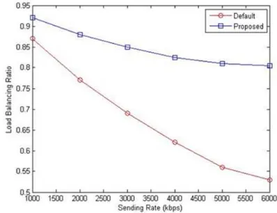
Figure 5 shows the comparison of load balancing ratio between the proposed algorithm and the default handover scheme. It is observed from Figure 5 that the load balancing ratio for the default handover scheme decreases significantly when the sending rate is increased. The proposed algorithm achieves a higher load balancing ratio (e.g., a more balanced load distribution) than the default handover scheme. The reason is that the proposed algorithm can appropriately transfer a part of users from the over-loaded cell to the under-loaded cell to balance the load.
Figure 3. Comparison of z values among the proposed algorithm, the
exhaust search approach, and the default handover approach.
Figure 4. Comparison of average RB utilization ratio between the proposed
algorithm and the default handover scheme.
Figure 5. Comparison of load balancing ratio between the proposed
algorithm and the default handover scheme.
5.2.3. End-to-end Delay Evaluation
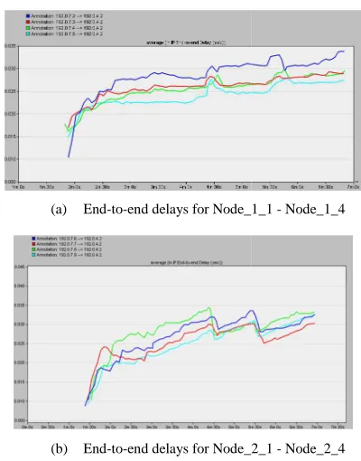
Figure 6 illustrates the end-to-end delay between UEs and eNBs. As shown in the figure, all traffic starts after around 100 seconds. After several seconds, the values of end-to-end delays become steady. In eNodeB_1, the values remain at around 0.025s, while in eNodeB_2, the delay values vary between 0.024s and 0.028s. That is due to different distances between the UEs and eNodeB, which leads to different channel conditions.
In order to evaluate the load distribution among cells, additional traffic is added to Node_2_1, Node_2_2, Node 2_3, and Node_2_4. The additional traffic is injected at the 3rd minute from the beginning, and we observe the change of end-to-end delay before and after the traffic injection. Figure 7 shows the end-to-end delays of the UEs after inserting the traffic flow. As shown in the Figure 7(a), the UEs’ delay at eNodeB_1 does not have too much change compared with the value before the traffic injection. Because the two cells are separated, the traffic injection in cell 2 does not affect the cell-1 network. Figure 7(b) shows the delays in default hand-over scheme, the delay values of all four nodes connected to eNodeB_2 start to increase from the third minute, and finally go above 0.04 second. The traffic injection makes the channel condition of Node_1_1, Node_1_2, Node_1_3 and Node_1_4 worse. However, the SINR values do not reach the thresholds. Therefore, the UEs do not take any hand-over action, so that the end-to-end delays are increased.
In this case, Node_2_3 switches its SeNB from eNodeB_2 to eNodeB_1. After the handover, the end
become acceptable. Node_1_1 to Node_1_4 hav fluctuations at this time which are caused by the handover. With more traffic injected, the end-to-end delays soar again. At the time of 5 minute 20 seconds, the SeNB of Node_2_1 is also switched to eNodeB_1, which leads to ano
reduction in Figure 8(b).
(a) End-to-end delays forNode_1_1
(b) End-to-end delays forNode_2_1
Figure 7. End-to-end delays with the default handover scheme after adding
traffic flows.
(a) End-to-end delays for Node_1_1
(b) End-to-end delays for Node_2_1
Figure 8. End-to-end delays with the proposed algorithm after adding
traffic flows.
In this case, Node_2_3 switches its SeNB from eNodeB_2 to eNodeB_1. After the handover, the end-to-end delays to Node_1_4 have tions at this time which are caused by the handover. end delays soar again. At the time of 5 minute 20 seconds, the SeNB of Node_2_1 is also switched to eNodeB_1, which leads to another delay
end delays forNode_1_1 - Node_1_4
end delays forNode_2_1 - Node_2_4
end delays with the default handover scheme after adding
end delays for Node_1_1 - Node_1_4
end delays for Node_2_1 - Node_2_4
end delays with the proposed algorithm after adding
In summary, Node_1_1 to Node_1_4 are connected to eNodeB_1, and Node_2_1 to Node_2_4 are connected to eNodeB_2. Due to the addi
eNodeB_2, Node_2_3 was handed over from eNodeB_2 to eNodeB_1 at time of 260 seconds, and Node_2_1 was handed over from eNodeB_2 to eNodeB_1 at time of 320 seconds. The handover is triggered by the proposed algorithm.
6. Conclusion
In this paper, we investigated the LTE load balancing problem. We proposed a practical load balancing algorithm for LTE networks to increase the load balancing ratio. We conducted experiments in OPNET. The experiments results demonstrated that the proposed algorithm can lead better load balance than the default handover scheme.
References
[1] 3GPP TS 36.211: “Evolved Universal Terrestrial Radio Access (E-UTRA); Physical channels and modulation”, 3GPP, ver. 9.1.0, rel. 9, 2010
[2] A. Ghosh and R. Ratasuk, Essentials of LTE and LTE Cambridge University Press, 2011.
[3] F. D. Cardoso and L. M. Correia, efficiency in LTE,” in proc. of
Communications and Networking Conference (WCNC), Shanghai, April 2012.
[4] OPNET Modeler network simulation software [Online]. Available: www.opnet.com.
[5] I. Viering, M. Dottling and A. Lobinger, “A mathematical perspective of self-optimizing wireless networks,” in proc. of 2009 IEEE International Conference on Communications, June 2009.
[6] A. Lobinger, S. Stefanski, T. Jansen, and I. Balan, “Load balancing in downlink LTE self
proc. of 2010 IEEE 71st Vehicular Technology Conference (VTC 2010-Spring), May 2010.
[7] K.A. AliHossam H.S. Hassanein and H.T. Mouftah, “Directional cell breathing based reactive congestion control in WCDMA cellular networks,” in proc. of 2007 IEEE 12th Symposium on Computers and Communications (ISCC), July 2007.
[8] J. G. Andrews, R. K. Ganti, M. Haenggi, N. Jindal and S. Weber, “A primer on spatial m
wireless networks,” IEEE Communications Magazine, vol. 48, no. 11, pp. 156--163, 2010.
[9] M. M. Tantawy, A. S. T. Eldien and R. M. Zaki, “A novel cross-layer scheduling algorithm for Long Term
(LTE) wireless system,” Canadian and Wireless Networks, vol. 2, no. 4, pp. 57
[10] Z. Li, H. Wang, Z. Pan, N. Liu and X. You, “Joint optimization on load balancing and network load in 3GPP LTE multi-cell networks,” in proc. of 2011 IEEE International Conference on Wireless Communications and Signal Processing (WCSP), Nov
Node_1_1 to Node_1_4 are connected to eNodeB_1, and Node_2_1 to Node_2_4 are connected to to the additional traffic injection to eNodeB_2, Node_2_3 was handed over from eNodeB_2 to eNodeB_1 at time of 260 seconds, and Node_2_1 was handed over from eNodeB_2 to eNodeB_1 at time of 320 seconds. The handover is triggered by the proposed
, we investigated the LTE load balancing
practical load balancing algorithm
increase the load balancing ratio. We conducted experiments in OPNET. The experiments results oposed algorithm can lead to a better load balance than the default handover scheme.
: “Evolved Universal Terrestrial Radio UTRA); Physical channels and modulation”, 9.1.0, rel. 9, 2010.
Ratasuk, Essentials of LTE and LTE-A, Cambridge University Press, 2011.
F. D. Cardoso and L. M. Correia, “MIMO gain and energy in proc. of 2012 IEEE Wireless Communications and Networking Conference (WCNC),
odeler network simulation software [Online]. Available: www.opnet.com.
I. Viering, M. Dottling and A. Lobinger, “A mathematical optimizing wireless networks,” in proc. of 2009 IEEE International Conference on Communications,
A. Lobinger, S. Stefanski, T. Jansen, and I. Balan, “Load balancing in downlink LTE self-optimizing networks,” in proc. of 2010 IEEE 71st Vehicular Technology Conference
Spring), May 2010.
K.A. AliHossam H.S. Hassanein and H.T. Mouftah, nal cell breathing based reactive congestion control in WCDMA cellular networks,” in proc. of 2007 IEEE 12th Symposium on Computers and Communications (ISCC),
J. G. Andrews, R. K. Ganti, M. Haenggi, N. Jindal and S. Weber, “A primer on spatial modeling and analysis in wireless networks,” IEEE Communications Magazine, vol.
163, 2010.
M. M. Tantawy, A. S. T. Eldien and R. M. Zaki, “A novel layer scheduling algorithm for Long Term-Evolution (LTE) wireless system,” Canadian Journal on Multimedia and Wireless Networks, vol. 2, no. 4, pp. 57-62, Dec. 2011.
[11] D. Chiu and R. Jain, “Analysis of the increase and decrease algorithms for congestion avoidance in computer networks,” Computer Networks and ISDN Systems, vol. 17, no. 1, Jun. 1989.
[12] Y. Yuan and Z. Chen, “A study of algorithm for LTE
intra-frequency handover.” in proc. of 2011 International Conference on Computer Science and Service System (CSSS), Nanjing, Jun. 2011.