http://www.sciencepublishinggroup.com/j/ajsea doi: 10.11648/j.ajsea.20170602.14
ISSN: 2327-2473 (Print); ISSN: 2327-249X (Online)
Determination of Rounded Edge Diffraction Loss for a
Plateau Using Hacking Method
Victor Akpaiya Udom, Kalu Constance, Asuquo Ifiok Okon
Department of Electrical/Electronic and Computer Engineering, University of Uyo, Uyo, Nigeria
Email address:
[email protected] (K. Constance)
To cite this article:
Victor Akpaiya Udom, Kalu Constance, Asuquo Ifiok Okon. Determination of Rounded Edge Diffraction Loss for a Plateau Using Hacking Method. American Journal of Software Engineering and Applications. Vol. 6, No. 2, 2017, pp. 35-39. doi: 10.11648/j.ajsea.20170602.14
Received: January 3, 2017; Accepted: January 18, 2017; Published: June 12, 2017
Abstract:
In this paper, Hacking rounded edge diffraction loss method is used to determine the diffraction loss over a plateau in the path of microwave signal in the GSM frequency band, 800 MHz to 2100 MHz. The computation is based on the path profile with path length of 4996.243 m and a plateau in the signal path. The plateau has maximum elevation of 268.9 m and it occurred at a distance of 3557.8 m from the transmitter. The line of sight clearance height is 45.747499 m and occultation distance is 1538.759 m. At 800 MHz, the diffraction loss is 55.25 dB whereas at 2100 MHz the diffraction loss is 71.713 dB. The result is useful for GSM network planning.Keywords:
Rounded Edge Diffraction, Diffraction Loss, Elevation Profile, Diffraction Parameter, Knife Edge Diffraction, Hacking Rounded Edge Diffraction Method1. Introduction
A plateau is an area of fairly level high ground. When an isolated plateau is located in the path of microwave signal it constitutes an obstruction. As an obstruction, the plateau will cause diffraction loss [1-5]. Like other obstructions such as hill and building, the plateau can be approximated as knife edge obstruction. However, approximation will under-estimate the diffraction loss that can be caused by the plateau [6, 7]. In that case, a rounded edge obstruction approximation is preferable [8-14].
In this paper, determination of rounded edge diffraction loss for a plateau using Hacking method [15-19] is presented for 800 MHz to 2100 MHz GSM (Global System for Mobile communication) frequency band. The study utilizes the path profile of a microwave link with a plateau in the signal path to construct the rounded edge geometry which is then used to determine the rounded edge diffraction loss expected from the plateau.
2. Theoretical Background
2.1. The Rounded Plateau Obstruction Geometry and Parameters
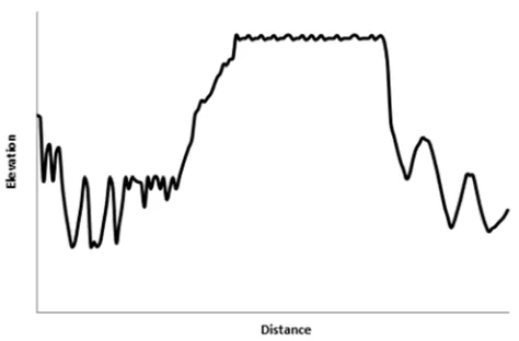
Figure 1 shows the elevation profile of a plateau obstruction
between the transmitter (T) and the receiver (R).
Figure 1. The Elevation Profile Of A Plateau As The Obstruction In The
Signal Path.
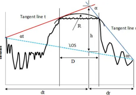
way that the circle is tangential to the two tangential lines to the elevation profile. In this paper, the tangent line t, the tangent line r, their tangent points and their lengths denoted as S1 and S2 are determined by drawing the tangent line t and tangent line r on the graphical plot of the path profile. Also, the length of the line of sight (LOS) denoted as S3 is measured out from the graph plot of the path profile.
Figure 2. The Elevation Profile Of The Plateau Obstruction With Tangential
Lines And Fitted Circle At The Vicinity Of The Plateau Vertex.
Figure 2 shows the essential parameters required for the rounded plateau top diffraction loss computation. The key dimensions include:
i. S1: the length of (tangent line t) the tangent from the transmitter to the intersection point of tangent line t and tangent line r.
ii. S2: the length of (tangent line r) the tangent from the receiver to the intersection point of tangent line t and tangent line r.
iii. S3: the length of the line of sight (LOS) which is the line from the transmitter to the receiver.
iv. β: The LOS is inclined at angle β to the horizontal. The angle which the LOS makes with the horizontal is denoted as β where;
β (1)
where
H is the elevation of the transmitter and H is the elevation of the receiver. H and H are obtained from the path profile data.
v. d1: the horizontal distance from the transmitter to the intersection point of the two tangents
vi. d2: the horizontal distance from the receiver to the intersection point of the two tangents
vii. d is the path length, that is the distance between the transmitter and the receiver, and d is given as;
d = d d (2)
d and d are measured from the graph plot and the
intersection point of tangent line t and tangent line r
viii. D: the occultation distance, which is the distance
between the tangent point before and the tangent point after the intersection point of tangent line t and tangent line t. D is the distance between the tangent point of tangent line t with the path profile and the tangent point of tangent line r with the path profile. In this paper, the tangent points are determined by drawing the tangent line t and tangent line r on the graphical plot of the path profile. Then, D is measured from the graph plot as the distance between the tangent points of tangent line t and tangent line r.
ix. αt: the angle between the LOS and (tangent line t) the tangent line drawn from the transmitter to the elevation profile.
x. αr: the angle between the LOS and (tangent line r) the tangent line drawn from the receiver to the elevation profile.
The angles αt and αr are obtain by cosine rule as follows;
Cos αt ! "% & &$ # !$ " !% " (3)
αt Cos ! "% & &$ # !$ " !% " (4)
Similarly,
αr Cos ! %% &% &$ "# !$ " ! " (5)
The angle α is given as;
α αt αr (6) xi. ( is the height of the intersection point of tangent line t and tangent line r above the LOS. ( is the height of the intersection point of tangent line t and tangent line r above the LOS. h is given as;
h ! *!+, - .!+, /0 1 (7)
xii. v is he diffraction parameter which is given as;
v (35% 4 #4% % (8)
xiii. R is the radius of the circle fitted to the plateau in the vicinity of the plateau vertex. The radius of the circle fitted in the vicinity of the hill vertex. The circle fitted in the vicinity of the hill vertex is tangential to the tangent line t and tangent line r. The approximate value of R is estimated from the path profile using the formula [20, 21];
6 - *% 7 " # % % " . (9)
2.2. Hacking Method for Computing Diffraction Loss over Rounded Edge
According to Hacking method for diffraction loss on rounded edge, the total diffraction loss, A49 : is given as;
Where
A;< is the knife edge diffraction loss
v is the diffraction parameter as given in Eq 8.
=<>is the excess diffraction loss which is added to the
knife edge diffraction loss to account for the rounded hilltop.
The knife edge diffraction loss, A;< can be determined by Lee’s piecewise knife edge diffraction loss approximation model expressed in respect of diffraction parameter, v as follows [22, 23]:
A;< ?@ =
A B C B
D 20log 0.5 − 0.62v for − 1 ≤ v ≤ 0 0 for v < −1 20log 0.5exp −0.95v for 0 ≤ v ≤ 1 20log U0.4 − W0.1184 − 0.38 − 0.1v %Z for 1 ≤ v ≤ 2.4
20log 0.%%[\ for v > 2.4 ^B
_ B `
(11)
where
v is the diffraction parameter as given in Eq 8.
h is the line of sight (LOS) clearance height, h is in meters;
?a is the distance from the transmitter and ?bis the
distance from the receiver. ?aand ?bare is km. The excess diffraction loss according to Hacking is given as [15, 16]:
A c= 11.7 α e fg /$
(12)
Where
α is the exterior angle (in radian) between the tangent line drawn from the transmitter (referred to as tangent line t) and the tangent lines drawn from the receiver (referred to as tangent line r). α is given from Eq 6, Eq 3 and Eq 5. R is the radius of the circle fitted in the vicinity of the
obstruction vertex. R is given in Eq 9.
ʎ is the signal wavelength which is given as;
ʎ =jk (13)
f is the frequency in Hz and c is the speed of light which is 3x10l m/s.
3. Results and Discussions
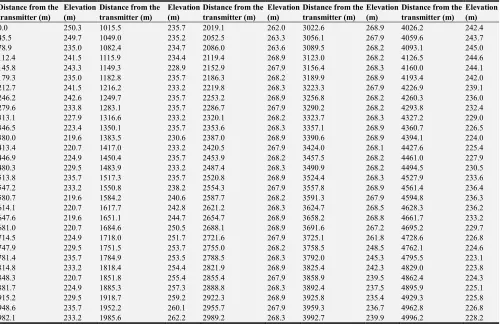
The study if conducted for the L-band microwave frequency which ranges from 1 GHz to 2 GHz. Specifically, the 1 GHz and 1.9 GHz frequencies are considered in this paper. The elevation profile data used for the study is given in Table 1. From Table 1 the elevation maximum elevation is 268.9 m and it occurred at a distance of 3557.8 m from the transmitter.
Table 1. The Elevation Profile For The Plateau.
Distance from the transmitter (m)
Elevation (m)
Distance from the transmitter (m)
Elevation (m)
Distance from the transmitter (m)
Elevation (m)
Distance from the transmitter (m)
Elevation (m)
Distance from the transmitter (m)
Elevation (m)
0.0 250.3 1015.5 235.7 2019.1 262.0 3022.6 268.9 4026.2 242.4
45.5 249.7 1049.0 235.2 2052.5 263.3 3056.1 267.9 4059.6 243.7
78.9 235.0 1082.4 234.7 2086.0 263.6 3089.5 268.2 4093.1 245.0
112.4 241.5 1115.9 234.4 2119.4 268.9 3123.0 268.2 4126.5 244.6
145.8 243.3 1149.3 228.9 2152.9 267.9 3156.4 268.3 4160.0 244.1
179.3 235.0 1182.8 235.7 2186.3 268.2 3189.9 268.9 4193.4 242.0
212.7 241.5 1216.2 233.2 2219.8 268.3 3223.3 267.9 4226.9 239.1
246.2 242.6 1249.7 235.7 2253.2 268.9 3256.8 268.2 4260.3 236.0
279.6 233.8 1283.1 235.7 2286.7 267.9 3290.2 268.2 4293.8 232.4
313.1 227.9 1316.6 233.2 2320.1 268.2 3323.7 268.3 4327.2 229.0
346.5 223.4 1350.1 235.7 2353.6 268.3 3357.1 268.9 4360.7 226.5
380.0 219.6 1383.5 230.6 2387.0 268.9 3390.6 268.9 4394.1 224.0
413.4 220.7 1417.0 233.2 2420.5 267.9 3424.0 268.1 4427.6 225.4
446.9 224.9 1450.4 235.7 2453.9 268.2 3457.5 268.2 4461.0 227.9
480.3 229.5 1483.9 233.2 2487.4 268.3 3490.9 268.2 4494.5 230.5
513.8 235.7 1517.3 235.7 2520.8 268.9 3524.4 268.3 4527.9 233.6
547.2 233.2 1550.8 238.2 2554.3 267.9 3557.8 268.9 4561.4 236.4
580.7 219.6 1584.2 240.6 2587.7 268.2 3591.3 267.9 4594.8 236.3
614.1 220.7 1617.7 242.8 2621.2 268.3 3624.7 268.5 4628.3 236.2
647.6 219.6 1651.1 244.7 2654.7 268.9 3658.2 268.8 4661.7 233.2
681.0 220.7 1684.6 250.5 2688.1 268.9 3691.6 267.2 4695.2 229.7
714.5 224.9 1718.0 251.7 2721.6 267.9 3725.1 261.8 4728.6 226.8
747.9 229.5 1751.5 253.7 2755.0 268.2 3758.5 248.5 4762.1 224.6
781.4 235.7 1784.9 253.5 2788.5 268.3 3792.0 245.3 4795.5 223.1
814.8 233.2 1818.4 254.4 2821.9 268.9 3825.4 242.3 4829.0 223.8
848.3 220.7 1851.8 255.4 2855.4 267.9 3858.9 239.5 4862.4 224.3
881.7 224.9 1885.3 257.3 2888.8 268.3 3892.4 237.5 4895.9 225.1
915.2 229.5 1918.7 259.2 2922.3 268.9 3925.8 235.4 4929.3 225.8
948.6 235.7 1952.2 260.1 2955.7 267.9 3959.3 236.7 4962.8 226.8
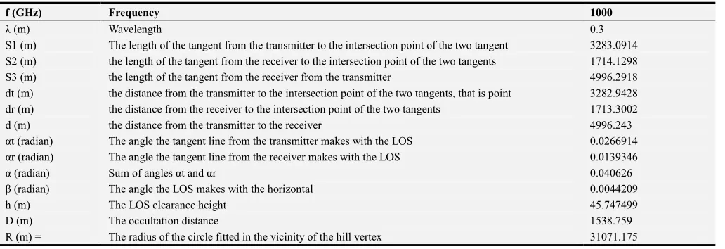
Table 2. Rounded Edge Parameters For The Plateau Obstruction.
f (GHz) Frequency 1000
λ (m) Wavelength 0.3
S1 (m) The length of the tangent from the transmitter to the intersection point of the two tangent 3283.0914
S2 (m) the length of the tangent from the receiver to the intersection point of the two tangents 1714.1298
S3 (m) the length of the tangent from the receiver from the transmitter 4996.2918
dt (m) the distance from the transmitter to the intersection point of the two tangents, that is point 3282.9428
dr (m) the distance from the receiver to the intersection point of the two tangents 1713.3002
d (m) the distance from the transmitter to the receiver 4996.243
αt (radian) The angle the tangent line from the transmitter makes with the LOS 0.0266914
αr (radian) The angle the tangent line from the receiver makes with the LOS 0.0139346
α (radian) Sum of angles αt and αr 0.040626
β (radian) The angle the LOS makes with the horizontal 0.0044209
h (m) The LOS clearance height 45.747499
D (m) The occultation distance 1538.759
R (m) = The radius of the circle fitted in the vicinity of the hill vertex 31071.175
Table 2 shows the key rounded edge parameters obtained for the plateau obstruction. From Table 2, the path length (d) is 4996.243 m. Also, the tangent from the transmitter and the tangent from the receiver intersected at a distance of 3282.9428 m from the transmitter and a distance of 1713.3002m from the receiver. The line of sight makes an angle of 0.0044209 radians with the horizontal. The LOS clearance height is 45.747499 m. The occultation distance is 1538.759 m.
Table 3 and figure 3 show the diffraction parameter and the diffraction loss for the rounded edge plateau as computed by the Hacking method. The diffraction parameter and also the
diffraction loss increases with frequency. At 800 MHz, the plateau will cause diffraction loss of 55.25 dB whereas at 2100 MHz the plateau will cause diffraction loss of 71.713 dB.
Table 3. The Diffraction Parameter and The Diffraction Loss For The
Rounded Edge Plateau Computed by The Hacking Method.
Frequency (MHz) Diffraction Parameter, V Diffraction Loss (dB)
800 3.148764 55.250
900 3.339769 57.051
1800 4.723146 68.804
1900 4.852571 69.811
2100 5.101581 71.713
Figure 3. The Diffraction Parameter and The Diffraction Loss For The Rounded Edge Plateau Computed by The Hacking Method.
4. Conclusions
Hacking rounded edge diffraction loss method is presented. The method is used to determine the diffraction loss over a plateau in the path of microwave signal in the GSM frequency band, 800 MHz to 2100 MHz. The computation is based on the path profile of a plateau. The results show how the diffraction parameter and the diffraction loss vary with frequencies within the given 800 MHz to 2100 MHz frequency band.
References
[1] Rao, P. S. (2013) Performance Analysis of Diffraction Gain (Gd) Due to presence of Knife-Edge as Compared to Free Space E-Field and Identifying the Position of Obstacle in a Fresnel Zone. International Journal of Scientific and Research Publications, Volume 3, Issue 1, January 2013.
[3] Akkaşlı, C. (2009). Methods for Path loss Prediction. Reports from MSI, School of Mathematics and Systems Engineering, Report, 9067.
[4] Fickenscher, M. R. T. (2014, March). Diffraction loss and phase modulation of terrestrial radio-link by wind turbine. In Antenna Technology:" Small Antennas, Novel EM Structures and Materials, and Applications" (iWAT), 2014 International Workshop on (pp. 382-384). IEEE.
[5] Klostius, R., Wieser, A., & Brunner, F. K. (2006, May). Treatment of diffraction effects caused by mountain ridges. In Proceedings of 3rd IAG/12th FIG Symposium, Baden.
[6] Durgin, G. D. (2009). The practical behavior of various edge-diffraction formulas. IEEE Antennas and Propagation Magazine, 51 (3), 24-35.
[7] Durgin, G. D. (2008, July). Practical geometrical behavior of knife-edge diffraction. In 2008 IEEE Antennas and Propagation Society International Symposium (pp. 1-4). IEEE.
[8] Gnani, F., Lo, K. H., Zare-Behtash, H., & Kontis, K. (2014). Experimental investigation on shock wave diffraction over sharp and curved splitters. Acta Astronautica, 99, 143-152. [9] Kizer, G. (2013). Digital microwave communication:
engineering point-to-point microwave systems. John Wiley & Sons.
[10] Vogler, L. E. (1985). Radio wave diffraction by a rounded obstacle. Radio science, 20 (3), 582-590.
[11] Gnani, F., Lo, K. H., Zare-Behtash, H., & Kontis, K. (2015). Shock Wave Diffraction Phenomena around Slotted Splitters. Aerospace, 2 (1), 1-16.
[12] Emerson, D., & Lewis, M. (2004). Propagation Models. Lewis & Emerson (2004), 48.
[13] Rathsam, J., & Wang, L. M. (2007). Scattered Responses From Suspended Reflector Panels With Rounded Edges.
[14] Mack, C. A. (2000). Corner rounding and round contacts. Microlithography World, summer.
[15] Parsons, J. D., & Parsons, P. J. D. (2000). The mobile radio propagation channel. Second edition. John Wiley & Sons. [16] Hacking, K. U. H. F. (1968). Propagation over rounded hills.
BBC Research Department. Research Report No. RA-21, 30.
[17] Hill, G. (2007). The Cable and Telecommunications Professionals' Reference: PSTN, IP and cellular networks, and mathematical techniques (Vol. 1). Taylor & Francis.
[18] McArthur, R. J., & Bebbington, D. H. O. (1991, April). Diffraction over simple terrain obstacles by the method of parabolic equations. In Antennas and Propagation, 1991. ICAP 91., Seventh International Conference on (IEE) (pp. 824-827). IET.
[19] Hacking K., (1970) "U. H. F. propagation over rounded hills", Proc. IEE, vol. 117, PP. 499-511, 1970.
[20] Seybold, J. S. (2005). Introduction to RF propagation. John Wiley & Sons.
[21] Barué, G. (2008). Microwave engineering: land & space radiocommunications (Vol. 9). John Wiley & Sons.
[22] Jude, O. O., Jimoh, A. J., & Eunice, A. B. (2016). Software for Fresnel-Kirchoff Single Knife-Edge Diffraction Loss Model. Mathematical and Software Engineering, 2 (2), 76-84.