INDUSTRIAL PROCESS VALIDATION OF SOLID DOSAGE FORMS: A REVIEW
8
0
0
Full text
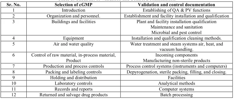
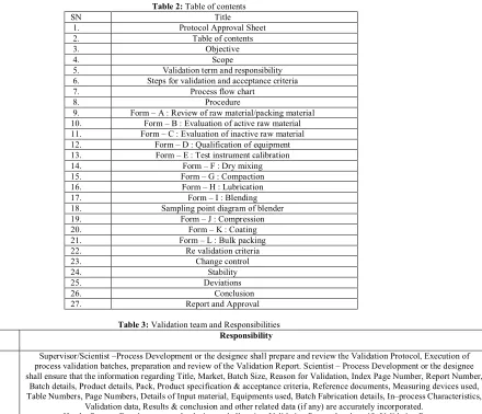
(2) Singh Harsimranjit et al. IRJP 2012, 3 (4) First, manufacturers are required by law to conform to cGMP regulations. Second, good business dictates that a manufacturer avoids the possibility of rejected or recalled batches. Third, validation helps to ensure product uniformity, reproducibility, and quality. Although the original focus of validation was directed towards prescription drugs, the FDA Modernization Act of 1997 expanded the agency’s authority to inspect establishments manufacturing over-the-counter (OTC) drugs to ensure compliance with cGMP. Once the concept of being able to predict process performance to meet user requirements evolved, FDA regulatory officials established that there was a legal basis for requiring process validation. The ultimate legal authority is Section 501(a)(2)(B) of the FD&C Act, which states that a drug is deemed to be adulterated if the methods used in, or the facilities or controls used for, its manufacture, processing, packing, or holding do not conform to or were not operated or administrated in conformity with cGMP. The cGMP regulations for finished pharmaceuticals, 21 CFR 210 and 211, were promulgated to enforce the requirements of the act. FDA has the authority and responsibility to inspect and evaluate process validation performed by manufacturers. The cGMP regulations for validating pharmaceutical (drug) manufacturing require that drug products be produced with a high degree of assurance of meeting all the attributes they are intended to possess (21 CFR 211.100(a) and 211.110(a).2,9,10,11 STRATEGY FOR INDUSTRIAL PROCESS VALIDATION OF SOLID DOSAGE FORMS The strategy selected for process validation should be simple and straightforward. The following five points gives strategy for process validation: 1. The use of different lots of raw materials should be included. i.e., active drug substance and major excipient. 2. Batches should be run in succession and on different days and shifts. 3. Batches should be manufactured in the equipment and facilities designated for eventual commercial production. 4. Critical process variables should be set within their operating ranges and should not exceed their upper and lower control limits during process operation. Output responses should be well within finished product specifications. 5. Failure to meet the requirements of the Validation protocol with respect to process input and output control should be subjected to process requalification and subsequent revalidation following a thorough analysis of process data and formal discussion by the validation team.2,9 GUIDELINES FOR PROCESS VALIDATION OF SOLID DOSAGE FORMS Numerous factors should be considered when developing and validating solid dosage forms. As a means of providing a broad overview of these validation criteria, the following checklist/guideline as in Table 1, is provided for tablets and dry-filled capsules for inclusion in an in depth validation program.2,3 Objective of Process Validation To monitor the manufacturing process of the commercial batches of solid dosage form to be manufactured and generate data on the product characteristics. The validation activity is being taken up for the generation of Qualification Report thereby establishing documentary. evidence that the commercial batch products meet all Quality and designed specifications. It has been proposed that three commercial batches shall be taken up for the validation study. PROTOCOL FOR PROCESS VALIDATION The protocol for process validation is given from the tables 2, 3 & 4 as follows: DRY GRANULATION What type of dry granulation technique will be used? There are a variety of granulation processes that can be utilized. Granulation process is grouped as either “wet” or “dry”. Dry granulation is comprised of processes such as slugging or chilsonation and roll compaction. Each technique will produce granules with different physical properties and will require monitoring of different processing parameters. Dry granulation may be viewed as a pre-compression process that takes place off the press to provide added flexibility of dwell time and compression force. It offers better stability than wet granulation and it works when direct compression is not possible. It also improves the flow property by increasing the particle size. Direct compression also increases the density of low-density drugs. It decreases the elastic recovery of some compounds, thereby increasing final compactability. Dry granulation, on the other hand, calls for six steps: milling of drugs and excipient, mixing of milled powders, compression into large hard tablets called slugs; screening of slugs; mixing of lubricant; disintegrants and tablet compression. Dry granulation also requires roller compaction. In this process, the powder is fed into two counter-rotating rolls by either gravity or force-fed screws. Once the powder is drawn into the nip angle area, it rubs against the roll surface and undergoes pre-densification. As the material enters the roll gap, particles are deformed or fragmented to form ribbons. The ribbons are sized through a screen and tablet compression takes place. However, ribbon formation involves several variables including roll speed, roll pressure, horizontal and vertical feed screw speed and roller compactor design. Granule formation variables include milling speed, screen type and mesh size and blade configuration12. The dry granulation manufacturing process shown in figure 1. Roller unit The roller unit includes two equal diameter counter rotating rollers. Two different types of roll compactors are commercially available: fixed gap systems and those which allow variable gap size due to moveable rolls (Gerteis Maschinen Process engineering). The gap width between rollers is pre-defined and fixed when roll compactor with fixed rollers is used. In these systems material flow is controlled by screw feeder speed only to get a constant densification of the material between two rollers. In latter system even compaction force is achieved by control of both the gap width and the screw feeder speed. Additionally, movable gap systems have less by pass propensity. By changing roll gap, density profile of the compacts can also be changed with changed robustness of the granules which subsequently effect mechanical properties of the tablets. In fixed gap systems ribbons of same geometrical dimensions are produced but non homogenous powder feed between the rollers is observed which leads to a change in porosity of the produced ribbons and variation in compaction pressure is also observed. This may lead to non desirable changes in product quality. In variable gap systems, at a given compaction Page 64.
(3) Singh Harsimranjit et al. IRJP 2012, 3 (4) pressure, actual gap size mainly results from screw feeder speed, roll speed and density of the fed powder. Thus, transportation of non-free-flowing powder and resulting changes in powder density may only lead to gap size variations which causes non-uniform ribbon thickness, with negligible effects on porosity due to maintenance of constant compaction pressure. Bypass is un-granulated material that circumvents the rolls completely, or passes between the rolls without being adequately compacted and is major cause of segregation of blend and consequently content uniformity. Three major factors which influence bypass includes roller surface roughness/design, roll orientation and vacuum de-aeration. 1316. Roll surface roughness/design The roll surface is important in maintaining a back pressure on the powder flow so that the powder does not pass through the nip region faster than the rolls are turning. Bypass can be minimized by use of rolls having greater roll roughness or use of textured surface (knurled). Three different types of continuous ribbon rolls are available with different surface designs intended to maintain this back pressure. These include knurled roll, serrated roll and smooth roll17. Roller orientation Three types of roll orientation are commercially available as: • Horizontal orientation: available from Hosokawa Bepex GmbH, The Fitzpatrick company, Freund Industrial Co. • Vertical orientation: available from Alexanderwerk AG •In-cline orientation (position between horizontal and vertical): available from Gerteis Maschinen + Processengineering AG 1: Filling hopper, 2: Feeding auger/screw feeder, 3: Tamping auger, 4: Rolls, 5: Flake crusher, 6: Granulator, 7 and 8: Two stage diagonal granulation system using coarse and fine granulator, respectively. The roll orientation plays significant role in generation and minimization of bypass. In horizontal roll orientation the loss of material due to bypass is high as compared to other designs. Loss of un-compacted material is minimal in vertical orientation due to independence of feed to gravitational forces. The use of inclined roll orientation decreases bypass from 15-20% to 7%. In horizontal orientation material may remain in nip region for certain, uncontrolled time period which may negatively affect ribbon uniformity. Incorporation of side seals (sealing strips) in compactor design reduces material bypass but this does not have significant effect to reduce material passing through the rolls without being sufficiently compacted. 14,18. Vacuum de-aeration This is an optional feature and usually applied during feeding to remove excess air from a fine powder with low bulk density. The application of vacuum eliminates entrained air that can cause the powder to resist the pre-compression force applied by the screw feeder. This technique is particularly useful for process with no screening or recycling steps or for greatly increasing the compaction efficiency of roll compactor19. Granulator/mill system Granulation/milling of ribbons or biquerette obtained from compaction can be done using an in-line oscillating rotorgranulator or separate granulation in an oscillating mill, a cone mill or impact mill. In most of the equipments in-line granulator can be used in two ways viz. use of coarse and fine. (two stage) granulator (WP120 Pharma, Alexanderwerk AG, Germany) to get desired sized granules or use of fine (single stage) granulator (WP150 Pharma, Alexanderwerk AG, Germany) in which fines and oversize are separated using sifter and recycled via vacuum conveying system. An in-line rotor granulator system consists of a rotor that runs in a conventional U-shaped or diagonal positioned screen. The rotor pulls the material into the working gap and crushes it allowing the material to pass through the desired mesh size. By the use of diagonal oriented screen output is increased due to more mass holding of the material against the screen as compared to conventional U-shaped screen. GENERAL OPERATIONAL PRINCIPLES Typical roller compaction processes consist of the following steps: ●Convey powdered material to compaction area (normally with screw feeder). ●Compact powder between two counter-rotating rolls with applied forces. ●Mill compact (sheet, flake or briquette) to desired particle size distribution. REASONS TO USE ROLLER COMPACTION There are several reasons for using roller compaction technology: ● No or low dust, increased safety when working with toxic or explosive materials. ● Improved flow characteristics. ● No segregation of components. ● increased bulk density. ● increased particle size. ADVANTAGES ● Simple process (no wetting or drying steps). ● Moisture-sensitive products can be processed. ● Heat-sensitive products can be processed. ● Drug and color migration do not occur. ● Shorter disintegration times can be obtained (if no binder is used). ● Less equipment, cost, and space are required. ● Continuous process. DISADVANTAGES ● Dissolution can be adversely affected, due to densification; ● Powders must be compressible (if primary product powder is not compressible, then a compressible component must be added to the formulation); ● Usually requires the addition of a lubricant to minimize sticking to the rolls. COMPACTION THEORY As the powder is compacted, it passes through three different regions or zones. Slip zone Deaeration of the powder occurs in this region. Powder is forced into the gap between the rolls via a sliding motion that results from the rotation of the feed screw and roll surfaces. Internal friction coefficient of powder determines the size of the slip zone (larger coefficient _ smaller slip zone _ longer compaction time). Nip zone Defined by the nip angle (a) which is determined theoretically by the compression factor, roll/powder friction angle, and the internal friction angle. Starts where no slippage of powder occurs at the roll surface. Powder is carried into the roll gap at the same speed as the roll surface. To achieve acceptable compaction, the nip angle must be large or Page 65.
(4) Singh Harsimranjit et al. IRJP 2012, 3 (4) residence time in the nip zone must be increased to permit particle bonding to occur Release zone Elastic recovery (expansion) of the compacted sheet occurs as it is released from the rolls. Expansion of the compact is a function of the physical characteristics of the material, roll diameter, and roll speed. More effective deaeration of the powder reduces the expansion due to improved bond formation (conversion to plastic deformation as opposed to elastic)20. TABLET COMPRESSION Compression is a critical step in the production of a tablet dosage form. The materials being compressed will need to have adequate flow and compression properties. The material should readily flow from the hopper onto the feed frame and into the dies. Inadequate flow can result in “rat holing” in the hopper and/or segregation of the blend in the hopper/feed frame. This can cause tablet weight and content uniformity problems. As for the compressibility properties of the formulation, it should be examined on an instrumented tablet press. Factors to consider during compression are as follows: · Tooling: The shape, size, and concavity of the tooling should be examined based on the formulation properties and commercial specifications. For intagliated (embossed) tablets, factors such as the position of the intagliation on the tablet and the intagliation depth and style should be examined to ensure that picking of the intagliation during compression or fill-in of the intagliation during coating does not occur. · Compression speed: The formulation should be compressed at a wide range of compression speeds to determine the operating range of the compressor. Is a force feeder required to ensure that sufficient material is fed into the dies? · Compression/ejection force: The compression profile for the tablet formulation will need to be determined to establish the optimal compression force to obtain the desired tablet hardness. The following in-process tests should be examined during the compression stage: 1. Appearance 2. Hardness 3. Tablet weight 4. Friability 5. Disintegration 6. Weight uniformity Tablet Coating Tablet coating can occur by different techniques (e.g., sugar, film, or compression). Film coating has been the most common technique over recent years and will be the focus of this section. Key areas to consider for tablet coating include the following: · Tablet properties: Tablet properties such as hardness, shape, and intagliation (if required) are important to obtain a good film-coated tablet. The tablet needs to be hard enough to withstand the coating process. · Equipment type: The type of coater will need to be selected. Conventional or perforated pan and fluid bed coaters are potential options. · Coater load: What is the acceptable tablet load range of the equipment? Having too large a pan load could cause attrition of the tablets because of the overall tablet weight. in the coater. In the case of a fluid bed coater, there may not be sufficient airflow to fluidize the tablets. · Pan speed: What is the optimal pan speed? This will be interrelated to other coating parameters, such as inlet temperature, spray rate, and flow rate. · Spray guns: The number and types of guns should be determined in order to efficiently coat the tablets. The spray nozzles should be sized properly to ensure even distribution over the tablet bed and to prevent clogging of the nozzles. The location and angle of the spray gun(s) should be positioned to get adequate coverage. Having the guns positioned too close together can lead to a portion of the tablets to be over wet. · Application/spray rate: The optimal application/spray rate should be determined. Spraying too fast will cause the tablets to become over wet, resulting in clumping of tablets. Spraying too slowly will cause the coating materials to dry prior to adhesion to the tablets. This will result in a rough tablet surface and poor coating efficiency. · Tablet flow: The flow or movement of the tablets in the coater should be examined to ensure proper flow. There should be sufficient tablet bed movement to ensure even distribution of the coating solution onto the tablets. The addition of baffles may be required to provide adequate movement of tablets for tablet coating. · Inlet/outlet temperature and airflow: These parameters are interrelated and should be set to ensure that the atomized coating solution reaches the tablet surface and then is quickly dried. · Coating solution: The concentration and viscosity of the coating solution will need to be determined. The solution will need to be sufficiently diluted in order to spray the material on the tablets. The concentration of the coating solution will also determine the amount and volume of solution to be applied to the tablets. · Coating weight: A minimum and maximum coating weight should be established for the tablet. Sufficient coating material should be applied to the tablets to provide a uniform appearance; however, it should not be great enough to cause fill-in of the intagliation. · Residual solvent level: If solvents are used for tablet coating, the residual solvent level will need to be determined. Appearance testing of the tablets is critical during the coating operation. Items to look for include the following: 1. Cracking or peeling of the coating 2. Intagliation fill-in 3. Surface roughness 4. Color uniformity 5. Coating efficiency should be determined for the coating operation. The efficiency will determine the amount of coating solution overage that may be required. In-process tests 1. Moisture content of “dried granulation” 2. Granulation particle size distribution 3. Blend uniformity 4. Individual tablet/capsule weight 5. Tablet hardness 6. Tablet thickness 7. Disintegration 8. Impurity profile Page 66.
(5) Singh Harsimranjit et al. IRJP 2012, 3 (4) Finished product tests 1. Appearance 2. Assay 3. Content uniformity 4. Tablet hardness 5. Tablet friability 6. Impurity profile 7. Dissolution These key test parameters are the yardsticks by which the major processing variables in solid dosage forms are evaluated. Some processing variables are: · Mixing time and speed of blenders · Roller pressure and speed, screw speed, roller gap and screen size · Time, temperature, and airflow conditions in coaters · Machine speed and compression force in tablet presses Process validation testing is generally done on the first three batches of product made in production-size equipment. Revalidation testing is only done when a “significant” change has occurred. A significant change is one that will alter the in-process or final product specification established during the validation program or a change in formula, process, or equipment. CHANGE CONTROL Process validation of a solid dosage form should include an SOP to reassess a process whenever there are significant changes in the process, equipment, facilities, reactants, process materials, systems, and so on that may affect the critical quality attributes and specifications of the solid dosage forms. Such changes should be documented and approved in accordance with the scope of the change control SOP. The change control SOP should consist of the following elements: · Documentation that describes the procedure, review, approval, and basis for formal revalidation studies. · Identification of the change and assessment of its likely implication. · Requirements for monitoring change and testing needs. · Assessment of information and justification for the change. Sr. No. 1 2 3 4 5 6 7 8 9 10 11 12. · Review and formal approval to proceed. · Identification of changes made to the physical and chemical composition of the solid dosage forms. · Possible regulatory action and customer notification2,21. DOCUMENTATION Documentation at each stage of the process validation lifecycle is essential for effective communication in solid dosage form projects. Documentation is important so that knowledge gained about a product and process is accessible and comprehensible to others involved in each stage of the lifecycle. In addition to being a fundamental tenet of following the scientific method, information transparency and accessibility are essential so that organizational units responsible and accountable for the process can make informed, science-based decisions that ultimately support the release of a product to commercial scale. The degree and type of documentation required by CGMP is greatest during process qualification, and continued process verification. Studies during these stages must conform to CGMPs and must be approved by the quality unit in accordance with the regulations (21 CFR 211.22 and 211.100) 22-24. CONCLUSION Solid dosage form validation should be part of a comprehensive validation program within an industry. The multidisciplinary validation team must identify the product and process characteristics that must be studied and incorporate specific validation tests to ensure that product will meet all quality, manufacturing, and regulatory requirements. The total program should begin with validation of the active pharmaceutical ingredient (API) characteristics so that this material will be uniform batch after batch, providing a solid footing upon which the dosage form will be built. Scientific information obtained during the preformulation stage can form the basis for a well-designed and comprehensive validation program. Continued awareness of validation requirements and a diligent application of validation principles will thus help to ensure that pharmaceutical products will be able to be developed and produced with the quality and reproducibility required from regulatory agencies across the world.. Table 1: Check list of Validation and Control Documentation Selection of cGMP Validation and control documentation Introduction Establishing of QA & PV functions Organization and personnel. Establishment and facility installation and qualification Buildings and facilities Plant and facility installation qualification Maintenance and sanitation Microbial and pest control Equipment Installation and qualification cleaning methods. Air and water quality Water treatment and steam systems air, heat, and vacuum handling. Control of raw material, in-process material, Incoming components Product Manufacturing non-sterile products Production and process controls Process control systems (instruments and computers) Packing and labeling controls Depyrogenation, sterile packing, filling, and closing. Holding and distribution Facilities Laboratory controls Analytical methods Records and reports Computer systems Returned and salvage drug products Batch processing. Page 67.
(6) Singh Harsimranjit et al. IRJP 2012, 3 (4). SN 1. 2. 3. 4. 5. 6. 7. 8. 9. 10. 11. 12. 13. 14. 15. 16. 17. 18. 19. 20. 21. 22. 23. 24. 25. 26. 27.. FUNCTIONAL AREA Process Development. Validation Engineering Production Regulatory Affairs Quality Assurance (QA). Table 2: Table of contents Title Protocol Approval Sheet Table of contents Objective Scope Validation term and responsibility Steps for validation and acceptance criteria Process flow chart Procedure Form – A : Review of raw material/packing material Form – B : Evaluation of active raw material Form – C : Evaluation of inactive raw material Form – D : Qualification of equipment Form – E : Test instrument calibration Form – F : Dry mixing Form – G : Compaction Form – H : Lubrication Form – I : Blending Sampling point diagram of blender Form – J : Compression Form – K : Coating Form – L : Bulk packing Re validation criteria Change control Stability Deviations Conclusion Report and Approval Table 3: Validation team and Responsibilities Responsibility. Supervisor/Scientist –Process Development or the designee shall prepare and review the Validation Protocol, Execution of process validation batches, preparation and review of the Validation Report. Scientist – Process Development or the designee shall ensure that the information regarding Title, Market, Batch Size, Reason for Validation, Index Page Number, Report Number, Batch details, Product details, Pack, Product specification & acceptance criteria, Reference documents, Measuring devices used, Table Numbers, Page Numbers, Details of Input material, Equipments used, Batch Fabrication details, In–process Characteristics, Validation data, Results & conclusion and other related data (if any) are accurately incorporated. Head – Process Development or the designee shall review Validation Protocol and certify Validation Report. Head – Validation or the designee shall review Validation Protocol and certify Validation Report. Head – Engineering or the designee shall review the equipment and area in perfect working condition as required, shall certify the above in Validation Protocol and Validation Report. Manager – Production or the designee shall review and ensure that the information regarding Batch details, Product details, Pack, Details of Input material, Equipments used, Batch Fabrication details, In–process Characteristics are accurately incorporated. Manager –Regulatory affairs or the designee shall review the Batch details, Product details, Pack Details of Input material with respect to the regulatory requirements. Head – Quality Assurance or the designee shall approve the Validation Protocol, Review of validation documents and approve the process.. Page 68.
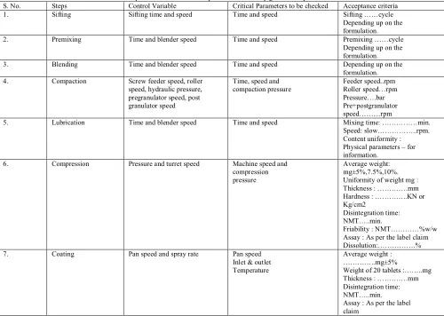
(7) Singh Harsimranjit et al. IRJP 2012, 3 (4) Table 4: Steps for validation and acceptance criteria in dry granulation process Control Variable Critical Parameters to be checked Sifting time and speed Time and speed. S. No. 1.. Steps Sifting. 2.. Premixing. Time and blender speed. Time and speed. 3.. Blending. Time and blender speed. Time and speed. 4.. Compaction. Screw feeder speed, roller speed, hydraulic pressure, pregranulator speed, post granulator speed. Time, speed and compaction pressure. 5.. Lubrication. Time and blender speed. Time and speed. 6.. Compression. Pressure and turret speed. Machine speed and compression pressure. 7.. Coating. Pan speed and spray rate. Pan speed Inlet & outlet Temperature. Acceptance criteria Sifting ……cycle Depending up on the formulation. Premixing ……cycle Depending up on the formulation. Depending up on the formulation. Feeder speed..rpm Roller speed…rpm Pressure….bar Pre+postgranulator speed………rpm Mixing time: ……………min. Speed: slow……………..rpm. Content uniformity : Physical parameters – for information. Average weight: mg±5%,7.5%,10%. Uniformity of weight mg : Thickness : ………….mm Hardness : …………..KN or Kg/cm2 Disintegration time: NMT…..min. Friability : NMT…………%w/w Assay : As per the label claim Dissolution:…………….% Average weight : …………..mg±5% Weight of 20 tablets :……..mg Thickness : ………….mm Disintegration time: NMT…..min. Assay : As per the label claim. Page 69.
(8) Singh Harsimranjit et al. IRJP 2012, 3 (4) REFERENCES 1. Aulton ME. pharmaceutics, the science of dosage form design, international edition, second edition, Churchill Livingston (Elsevier), 2006: 1. 2. Robert Nash A, Alfred Wachter A, Pharmaceutical Process Validation, Third Edition, volume 129, Marcel Dekker, Inc, New York, 2003:159180. 3. Herbert A, Leon Lachman L, Joseph B. Schwartz, Pharmaceutical Dosage Forms Tablets, second edition, volume 3, Marcel Dekker. Inc, New York, 1990: 417- 447. 4. Levin M, Pharmaceutical Process Scale-Up, Marcel Dekker, Inc., New York, 2002: 313. 5. www.wikipedia.com as on 25-06-2010. 6. FDA Guide on APIs, March 1998, page 48; PIC Guide, March 1999, page 32; Gold Sheet, Feb 1999: 6. 7. Chaitanya kumar G, Rout RP, Ramtake S, Bhattachaiya S, Process Validation, The Indian pharmacist, Aug 2005: 14-19. 8. Kathiresan K, Kiran K, Basics of Validation- Pharmaceutical Perspective, first edition, K.K. Publishers, \ Chidambaram, 2005: 32-46. 9. U.S. Food and Drug Administration. Guideline on General Principles of Process Validation; U.S. FDA: Rockville, MD, May, 1987. 10. Chapman KG. A history of validation in the United States, Part I. Pharm Tech 15(10), 1991: 82–96. 11. Tetzlaff RF, Sheppard RE, LeBlanc AJ. The validation story, Perspectives on the systemic GMP inspection approach and validation development. Pharm Tech March, 1993: 100–116. 12. Teng Y, Qiu Zand Wen H. Systematical approach of formulation and process development using roller compaction. Eur. J Pharm Sci 2009; 73(2): 219-229. 13. Horisawa E, Danjo K. Sunada H. Influence of granulating method on physical and mechanical properties, compression behavior, and. 14. 15.. 16. 17.. 18. 19. 20. 21. 22. 23. 24.. compactability of lactose and microcrystalline cellulose granules. Drug Dev Ind Pharm 2000; 26: 583-593. Bultmann JM. Multiple compaction of microcrystalline cellulose in a roller compactor. Eur J Pharm Biopharm 2002; 54: 59-64. Eggelkraut-Gottanka S Gvon A bed SA, Muller W, Schmidt PC. Roller compaction and tabletting of St John's wort plant dry extract using a gap width and force controlled roller compactor granulation and tabletting of eight different extract batches. Pharm Dev Technol 200; 7: 433-445. Rambali B, Baert L, Jans E, Massart DL. Influence of the roll compactor paramete settings and the compression pressure on the buccal bioadhesive tablet properties. Int J Pharm 2001; 220: 129-140. Ende M, Blackwood DO, Gierer DS, Neu CP. Challenges in development and scale-up of low-dose drug products by dry granulation: a case study. In:Formulation and analytical development for low-dose oral drug products, J Zheng (Ed.) John Wiley & Sons, Inc., New Jersey, 2009: 117-155. Farrenkopf J. Relevant aspects of roller compaction covering the impact of excipient, milling devices, fines and feasibility prediction Ph. D. Dissertation University of Heidelberg, 2010;1: 235. Wennerstrum S. Ten things you need to consider when choosing and installing a roller press system. Powder Bulk Technol 2000; 1-8. Timothy Smith J, Sackett G, Sheskly P, Liu L. Development, Scale-up and optimization of Process Parameters: Roll Compaction ; Chapter 31, page no.715-717. http://www.pharmainfo.net/reviews/validationessential-qualityassurance-tool pharmaindustries. http://www.pharmainfo.net/reviews/guidelinesgeneral- principlesvalidation-solid-liquid- andsterile- dosage-forms. www.processvalidation.com. www.picscheme.org.. Page 70.
(9)
Figure
Related documents
Results: Review of 92 papers and 10 interviews identified 56 categories of information needs related to the interpretation of PDDI information including drug and
OPM’s Central Personnel Data File (CPDF) is the most comprehensive, authoritative, and up-to-date database of federal executive branch employees, but it does not include information
Figure 4 – State Machine (source: [5]) The proposed changes to the state machine are marked in red (i) when the card is in the SELECTED state the R EAD R ECORD ( ) command and G
Among the plants tested Azima tetracantha (100 µg/ml) showed the highest rate of lymphocyte proliferation (76%), Indigofera tinctoria (100 µg/ml) showed maximum inhibition of
Based on the distribution of green and red algal genes in chromalveolate nuclear genomes, the model shown suggests that (i) chromalveolates are monophyletic, (ii) they acquired
With the introduction of VIVA bus rapid transit service, additional Trapeze modules have been implemented for the VIVA operations and maintenance contractor, Connex, who has
Therefore, for an athlete to make effective use of the returned energy, the forces from the surface must be exerted at the right location, in the proper direction, at the
Almighty God have mercy on you, forgive you all your sins through our Lord Jesus Christ, strengthen you in all goodness, and by the power of the Holy Spirit keep you in eternal
