3642
Computational Fluid Dynamics Of Hovering In
Flapping Insect Wings
K. Rajendra Prasad, G. Venkatasubbaiah, C. SyamsundarAbstract: In recent years, the Nano Aerial Vehicles (NAV) (or) Micro Aerial Vehicles (MAV) has taken an important role to access the remote places; it is been controlled and equipped with high definition camera and high quality Microphone with ability to continuity of approximately 24 hours. To mingle with the environmental as a stealth mode, most of the researcher focuses on the Flapping wing design. In this paper we focus on aerofoil design (NACA 4415, 2204, 2214) which is one of the most critical part of the vehicle responsible for lift and drag. Basically Aerofoil is the influencer of lift and drag of the any air vehicle. The Mesh model of the flapping wing is designed and the flow analysis of lift and drag coefficient was considered under laminar flow. The flapping wing is designed for low Reynolds number, which predominantly shows the unique results at lift verse angle of attack, the drag verse angle of attack, the pressure distribution of the flapping wings to assess the lift and the aerofoil drag coefficient. The obtained result shows the flow properties of the aerofoil and the overall vehicle has increased.
Index Terms: Flapping wing, glider wing, powerless flight wing, wing, high L/D ratio.
————————————————————
1
INTRODUCTION
Mavs and NAVs are currently use in over 50 countries. Such aircraft logged over 500,000 flight hours during the recent years increasing by logarithmic scale. Hundreds of different aircraft in various design, production or manufacturing stages. Seventy successful companies and almost 200 specific platforms are entering production or are currently under development. In recently, the top 50 programs accounted for nearly 3,000 aircraft deliveries and will produce 3,350 more in years— about 93 percent of the total production. Over the next five years, about 13,000 aircraft will be delivered by the same systems. Over our 2009-2018 forecast period, they will account for close to 65 percent of expected UAV deliveries [1]. All our development are the inspirational outcome from our mother nature. This analysis is also shows the similar interest over a flying organism which results in flapping wing model. The flow circulation at the bottom due to high camber at fore wing of the aerofoil and acceleration at the hind wing. The performance obtained has high gliding efficiency.
1.1 Flapping Bird vs. Flapping Bird Flight:
In Flapping bird wings its folding or expanding, wing twisting; wrist flexing or extending concepts are the same as for fixed-wing aircraft so its start by analyzing how the power and energy needed depend on the speed of the wing path of the aircraft. The Flapping birds in the body joint portion, marginal and angular covers with Angle in the mid part of the flapping wings have the smaller, median and larger secondary covers. Small birds like finches vary between flapping their wings when gliding and holding them folded (see Figure 1). We investigate this phenomenon in this paper and seek to discourage how often a bird can flap its wings. In Figure 2 the flapping concept of bird flights to set the tone for many other potential innovators and engineers to instigate future flapping flight phenomenon.
The micro aerial vehicle has become the important role to reach the dangerous environment.
Fig. 1. Examples of Flapping Wings (Birds Strokes)
Fig.2. Flapping Wing Micro Aerial Vehicle (MAV)
1.2 Flapping Insects vs. Flapping insects Flight:
In Flapping Insects wing it categorized with Direct flight Muscles (Fig 3) and Indirect flight muscles, the direct flight example the flutter wings elevator muscles pull wings up and depressor muscle pulls wing down. In indirect flight muscles
___________________________
• K. Rajendra Prasad is currently working as a Associate Professor, , Department of Mechanical Engineering, in CMR Engineering College, Medchal Road, Hyderabad, Telangana 501401.
• G. Venkatasubabaiah is currently working as a Professor, Department of Automobile Engineering, in MVSR Engineering College, Nadergul, Hyderabad, Telangana 501510.
3643 the honeybee vertical muscles pulls on the roof of the thorax,
causing the wings to rise, longitudinal muscles pulls the anterior and posterior ends of the thorax. In Flapping wing micro Aerial vehicle shows in Fig 4 is a complex system whose definition with biological flyers in nature, insects constitute a nonlinear periodical system with unorthodox contributors to flight aerodynamics, which is derived from an aerodynamic-body-dynamic model capturing the dominant physical aspects of the flow field. The periodic balance of the periodic method of nonlinear time Floquet theorem is used to test the stability of the periodic or-bit captured corresponding to the equilibrium that is hovering. The nano aerial vehicle has become the important role to reach the inaccessible places human recourses cannot be accessed.
Fig.3. Examples of Flapping Wings (Insects)
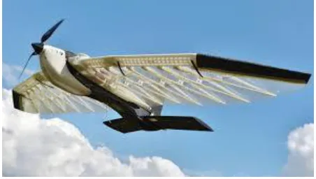
Fig.4. Flapping Wing Nano Aerial Vehicle (NAV)
The compassion between the flight of birds and insects that leads to relatively simpler aerodynamics in the flapping wing as an attempt to learn from nature to close model to their size and low power to weight ratio. The competition challenges its participants to design, create and fly the smallest aircraft capable of flying and taking pictures. The micro aerial vehicle (MAV) is generally defined as 6 to 8 inches, the nano aerial vehicle is generally defined as 0.5 inches in total size with a Reynolds chord number range from 50,000 to 150,000. The chord Reynolds number of MAV and NAV to the other flow regimes to follow different experimental, numerical and trial and error techniques to fully understand aerodynamics at low speed.
2
AERODYNAMIC
ANALYSIS
AND
RESULTS
The wing is solid works modelled and analysed on CFD. The work is two dimensional computational design analysis. For a chosen aerofoil, we are primarily keen on amplifying lift L and limiting the drag D, or on the other hand, augmenting the lift-to-drag proportion, L/D (likewise composed as the proportion of lift coefficient (Cl) to drag coefficient (Cd) or Cl/Cd,
characterized underneath). It is additionally important to watch out on the general effectiveness of a wing. This proportion relies upon wing geometry and wind current condition. These stream conditions are communicated as dimensionless parameters, for example, the Reynolds number Re and Mach number M. A chose airfoil profile will have unfathomably unique lift and drag qualities over the potential scopes of Re and M for a profile chose. In this manner, airfoils are commonly intended for a thin scope of stream conditions for ideal execution. Then again, one could structure an airfoil that will work over a wide scope of wind stream conditions. Lift capacity and drag ability of an airfoil is relied upon Lift and Drag coefficient, which is given as pursues.
L=0.5*ρ*V^2*S*Cl D=0.5*ρ*V^2*S*Cd
In addition, the total drag is further subdivided into drag numbers such as shape, weight, skin friction, parasite, induced & wave drag. In terms of wing geometry, the induced drag can be determined
D_i= (Cl^2)/πAR
Analysis of Airfoil NACA 2214
Considering st of rules and criteria for designing a wing. The obtained geometry is with Camber of 0.2 % chord, Thickness of 12.2 % chord and Chord of 0.1 m span .5 m. Under Standard Earth Atmospheric condition of Altitude 10000 m, with Density of 0.4137 kg / cu m, Pressure above 26.483 kPa , Temperature maintained -50 C of maximum conditions, with a Speed of 249.5 km/h. some of the obtained results are discussed below.
TABLE1
VALUES OF CI VARIES WITH ANGLE
Fig.5. Angle Vs Cl – Lift Versus AOA CL AOA CL
-10 -1.082 0 0.025 -9 -0.981 1 0.156 -8 -0.878 2 0.262 -7 -0.773 3 0.377 -6 -0.666 4 0.49 -5 -0.556 5 0.601 -4 -0.445 6 0.709 -3 -0.331 7 0.816 -2 -0.215 8 0.92 -1 -0.096 9 1.022
3644 Diagram Cl different which refers from the S2214 airfoils with
point shows the plot in Table 1 of the coefficient of lift versus approach for the NAV Flapping Wings for insctes which shown in fig 5 and the plot show generally excellent co-connection between the three distinct networks just as the exploratory information acquired from the UIUC site. The plot shows that the outcomes acquired from the three lattices differed from at least 0.215% to a limit of 1.122%. This demonstrates a wings work autonomous answer for the model. The arrangement contrast when contrasted for the flapping wing with right and left coverts with the test information changed from 0.3 % to 0.7 % the information acquired for the coefficient of drag for the S2214 as same as the flapping wing as shown the vertex angle for the right and left vertex wing. The plot shows that despite the fact that all the flapping wing models show results near one another with S2214 airofoils, the drag anticipated by the CFD model is marginally higher than that acquired by the trial esteems at UIUC. The rate variety in the drag coefficient for flapping wings changes from 0.6% at mid-run a from 0 to 2 degrees to a limit of 52% at higher approaches. Figure 7 shows the plot of L/D for the flapping wings which compertely the S2214 airfoils. Because of the higher drag anticipated by the CFD model the L/D for the UIUC information seems, by all accounts, to be higher than the L/D anticipated by the CFD model for approaches over two degrees.
TABLE2
VALUES OF CD VARIES WITH ANGLE
Fig.6. Angle Vs CD – Drag Versus
The outcomes got are plotted table 2. The drag coefficient differs from 2% at lower approaches to 6.2% at higher approaches. This outcomes which contrast and the S2214 Airfoil, the left and right wings of the fluttering wings which generally same as between the proportion ideas. For bigger perspective proportions in S2214 airfoils which gives high Reynolds number which anxiously contrast and fluttering wings are lower Reynolds number at both left and right changes over likewise for the airfoils examination it has been seen that the drag anticipated is higher and bring down the fluttering creepy crawlies wings. It gives off an impression of being a pattern in all the CFD reproductions for fluttering wings which gives the aside from the generally low 93 viewpoint proportion fluttering wings. The Bidule, as remarked by the creator was inclined to number of blunders and could likewise hold a probability of being incorrect.
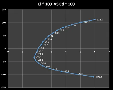
Fig 7. CL / CD Drag Polar Graph
TABLE 3
CL / CD vs Angle Graph
Cl Cd Cl * 100 Cd * 100
-1.082 0.059 -108.2 5.9
-0.981 0.047 -98.1 4.7
-0.878 0.037 -87.8 3.7
-0.773 0.029 -77.3 2.9
-0.666 0.024 -66.6 2.4
-0.556 0.021 -55.6 2.1
-0.445 0.019 -44.5 1.9
-0.331 0.018 -33.1 1.8
AOA CD * 100
-10 5.9
-9 4.7
-8 3.7
-7 2.9
-6 2.4
-5 2.1
-4 1.9
-3 1.8
-2 1.9
-1 2
0 2.1
1 2.3
2 2.4
3 2.6
4 2.8
5 3.1
6 3.4
7 3.8
8 4.4
9 5.1
3645
-0.215 0.019 -21.5 1.9
-0.096 0.02 -9.6 2
0.025 0.021 2.5 2.1
0.156 0.023 15.6 2.3
0.262 0.024 26.2 2.4
0.377 0.026 37.7 2.6
0.49 0.028 49 2.8
0.601 0.031 60.1 3.1
0.709 0.034 70.9 3.4
0.816 0.038 81.6 3.8
0.92 0.044 92 4.4
1.022 0.051 102.2 5.1
1.122 0.06 112.2 6
The coefficients of lift intently coordinate those of the exploratory qualities for fluttering wings with both ways vertex shudder wings lift muscles. All the 3 unique cross sections with surface body over fluttering wings and muscles examined give estimations of Q and Cd inside 6% variety. Along these lines the arrangement of S2214 Airfoil configuration could be said to be the vacillate wings framework autonomous to the air ship structure. From table 3 the CL/C_ V/s Alpha plots for CL edge the rate with alludes to 0.3% to 0.7 % and the C_D point as noted with 2% to % for the CFD examination results. It very well may be seen that Structured and Combination of lattices give results near that of the S2214 exploratory. The Coefficient of drag and lift is reproduced by CFD for fluttering wings has values lower Reynolds number than the test of S2214 airfoil plan. The bend intently coordinates the Flapping wings and ripple muscles to arrive at the normal after effects of the airframe structure. This pattern is likewise watched later in the investigation of the fluttering wings and MAV airframe where the drag anticipated is higher. The plot of Ci/Cd V/s Alpha shows that at least 2.5 to 112.2 territories the Q/C_ coordinates intently for lower approaches. After around 2 degrees the chart of the trial shows the Flapping wings and muscles looking at the CFD results shifts and the test estimations of Ci/C_ are a lot higher in S2214 Airfoil than those anticipated by CFD as lower in Flapping wings. This is because of the way that the co proficient of thee hauls anticipated by the CFD re-enactment is lower than that acquired for the exploratory outcomes to the fluttering wings. One of the significant perceptions ought to be noted in the fluttering wings and a muscle that was not seen was development of a partition close to the main edge of the association with backhanded airfoils structure equivalently with fluttering wings. Various streamlines were discharged close to the outside of fluttering wing and strong assortment of muscle the airfoil yet these demonstrated detachment just close to the division point towards the trailing edge of the fluttering wings. A significant examination of this investigation was to watch the expectation of laminar division of fluttering wings with high drag coefficient to lift weight of the structure of shudder wings. This was watched and could be said to be the fluttering wings of drag and lift coefficient to downside in the Fluent code for the investigation of stream at such low Reynolds numbers. Development of the division fluttering wings to relies upon pressure conveyance, edge variety surface ebb and flow, surface and strong harshness and choppiness. Every one of these components set up together outcome in the
development of division fluttering wings the propeller its shows to lift with high coefficient of the ripple plan. At significant the Hysteresis was additionally not seen because of no division fluttering wings development.
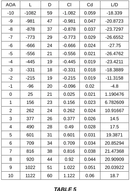
TABLE 4
Calculation of Lift and Drag angle
AOA L D Cl Cd L/D
-10 -1082 59 -1.082 0.059 -18.339
-9 -981 47 -0.981 0.047 -20.8723
-8 -878 37 -0.878 0.037 -23.7297
-7 -773 29 -0.773 0.029 -26.6552
-6 -666 24 -0.666 0.024 -27.75
-5 -556 21 -0.556 0.021 -26.4762
-4 -445 19 -0.445 0.019 -23.4211
-3 -331 18 -0.331 0.018 -18.3889
-2 -215 19 -0.215 0.019 -11.3158
-1 -96 20 -0.096 0.02 -4.8
0 25 21 0.025 0.021 1.190476
1 156 23 0.156 0.023 6.782609
2 262 24 0.262 0.024 10.91667
3 377 26 0.377 0.026 14.5
4 490 28 0.49 0.028 17.5
5 601 31 0.601 0.031 19.3871
6 709 34 0.709 0.034 20.85294
7 816 38 0.816 0.038 21.47368
8 920 44 0.92 0.044 20.90909
9 1022 51 1.022 0.051 20.03922
10 1122 60 1.122 0.06 18.7
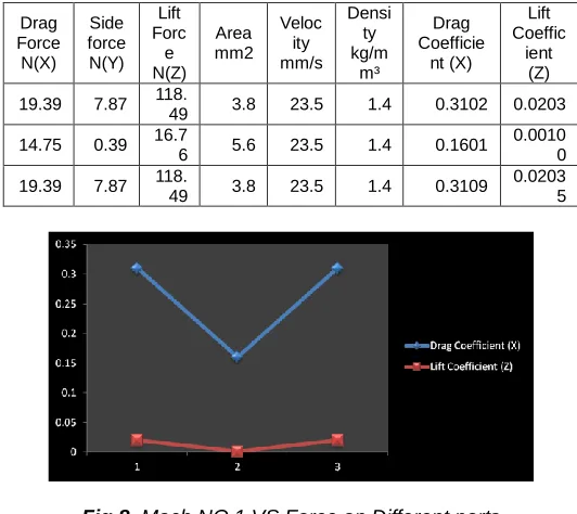
TABLE 5
Insect Model Reference Frames values
Calculation
For co-efficient of Drag & Lift
For fuselage withvelocity – 23.5 m/s at Mach no 0.1
Drag Co-efficient(CD)=2XFD/ρXV²XA=
3646 Drag co-efficient (CD) =0.3102
Lift co-efficient (CL)=2XFL/ρXV²XA= 2X7.87/1.4X23.5²X3.8
Lift co-efficient (CL) =0.0203
TABLE 6FORCE OF DIFFERENT PARTS
Drag Force N(X)
Side force N(Y)
Lift Forc e N(Z)
Area mm2
Veloc ity mm/s
Densi ty kg/m
m³
Drag Coefficie
nt (X)
Lift Coeffic
ient (Z)
19.39 7.87 118.
49 3.8 23.5 1.4 0.3102 0.0203
14.75 0.39 16.76 5.6 23.5 1.4 0.1601 0.00100
19.39 7.87 118.
49 3.8 23.5 1.4 0.3109 0.0203
5
Fig 8. Mach NO 1 VS Force on Different parts
Fig 9. Different Frames of Reference for (a) Aircraft and (b) Insect model.
2.1 INSECT MODEL REFERENCE FRAMES
With reference from different aircraft frames to describe the motion of the body with respect to an inertial frame as shown in Fig 8(a), the first reference frame is an inertial frame of Aircraft airfoil design. The absolute velocity and position of the NASA S2214 is described with respect to the Inertial frame. With reference to aircraft design the insect model frame as design as coordinate system with attaché dwith nano aerial vehicle (NAV) as designed using CATIA. The body frame is oriented with positive X – axis along the flutter structure to the longitudinal axis of the flutter bodies. The flapping wing is designed with reference to the Y-axis is perpendicular to the X-axis and its positive out to the left flapping and right flapping wings. The Z axis is positive downward to body portion and wing portion of the plane mass of both symmetric is assumed for the insect bodies.
Fig 10. Different Angle of NAV (Nano Aerial Vehicle)
2.2 GEOMETRY SELECTION AND MODELLING
The aerodynamics model has designed by using CATIA with reference to the NASA S2214, the same behaviour of a baseline of insects as designed Nano Aerial Vehicle (NAV shown in Fig 11). The investigation is displayed in steady state CFD analysis usig Ansys work bench(15.0) at Mach Number 0.1, by using CFD analysis the CL Co efficient of Lift and CD Co efficient of Drag are measured and look out the pressure and velocity shapes are plotted and the turbulence zone as justified.
Fig 11. Geometry of Model
2.3 MATHEMATICAL MESH MODEL
3647
Fig 12. Geometry Mesh in a domain
Fig 13. Mesh Model
Fig 14. Aerodynamics Force and Moments
With initial condition 23.5 velocity and free stream velocity in different direction of flapping wings towards the lift and drag prediction, by produce the CFD analysis as shown in Fig 13. The CFD analysis results shows the different angle of attack in
all the direction its clearly shows the lift force which have direct flow and the drag force is expressed in ensemble – average of the time series graph as plotted by using CFD analysis data.
4
CONCLUSIONS
The work provides the analysis of aerodynamics force and movement acting on a flapping wing (NAV) and on overall aerofoil design. The lift and drag co efficient of the insect model shows that the present analysis method, which shows unique performance at low Reynolds number. This provides that the new analysis is efficient than the current sectional study of the aero foils available. The top and bottom of the aerofoil flow are different at the velocity. So this provides low pressure difference which results upward force. The generation of lift is depended on the aerofoil’s top and bottom pressure difference. The flapping wing has a strong coefficient at the lift verse angle of attack and drag verse angle of attack, the pressure distribution on the design. It noticed that lift increased linearly with angle, until the stalls. The flapping wing designed at low Reynolds number’s result shows increase in flow properties over the aerofoil and the overall vehicle.
REFERENCES
[1]. Anjali Balani, Tarun Yadav, Appasaheb Malagaudanavar, ―COMPARATIVE CFD ANALYSIS OF AIRFOILS FOR UNMANNED AERIAL VEHICLES‖ International Journal of Research in Engineering and Technology, eISSN: 2319-1163 | pISSN: 2321-7308
[2]. Mayur S. Marathe & S. N. Bansode, ―Airfoil Selection of MAV (Miniature Air Vehicle) for Low Reynolds Number‖ International Journal on Theoretical and Applied Research in Mechanical Engineering (IJTARME), ISSN : 2319 – 3182, Volume-2, Issue-4, 2013.
[3]. Narayan U Rathod, ―Aerodynamic Analysis of a Symmetric Aerofoil‖, International Journal of Engineering Development and Research, 2014 IJEDR | Volume 2, Issue 4 | ISSN: 2321-9939
[4]. P. Lavoie, ―Low Reynolds Number Effects on the Aerodynamics of Unmanned Aerial Vehicles‖ Institute for aerospace studios, University of Toronto, center for research in sustainable aviation.
[5]. Alok Rege, ― CFD based aerodynamic modeling to study flight dynamics of a flapping wing micro air vehicle‖
https://www.researchgate.net/publication/258693513, 20 April 2016.
[6]. Taher I. Attari, ―CFD analysis and validation for solution to micro air vehicle airframes‖ http://scholarworks.rit.edu/theses, (2004). Thesis. Rochester Institute of Technology.
[7]. Naresh S, Dr.V. Ravi, ―Aerodynamic Characteristic Analysis of UAV (Unmanned Aerial Vehicle) By Using CFD‖ International Journal for Research in Applied Science & Engineering Technology, Volume 4 Issue VIII, August 2016, IC Value: 13.98 ISSN: 2321-9653 [8]. Weixing Yuan, Richard Lee & Luc Levasseur,
―Experimental and computational investigations of flapping wings for Nano-air-vehicles‖ Engineering Applications of Computational Fluid Mechanics199-219, DOI: 10.1080/19942060.2015.1004820, ISSN: 1994-2060 (Print) 1997-003X (Online) Journal
3648 Analysis and Optimization of UAV‖ InterFEA
Engineering, Tantalou 7 Thessaloniki GREECE. [10]. Khuntia SK* and Ahuja AS, ―Optimal Design and CFD
Analysis of Wing of a Small-Scale UAV to Obtain Maximum Efficiency‖ Journal of Aeronautics & Aerospace Engineering, Volume 7 • Issue 1 • 1000207 Aeronaut Aerospace Eng 2018, 7:1