IJSRST162125 | Received: 1 March 2016 | Accepted: 31 March 2016 | March-April 2016 [(2)2: 61-65]
© 2016 IJSRST | Volume 2 | Issue 2 | Print ISSN: 2395-6011 | Online ISSN: 2395-602X Themed Section: Engineering and Technology
61
Effect of Cell Potentials on Gas Diffusion Layer Velocity with
Serpentine Flow Channel in PEM Fuel Cell
Dr. R. Rajappan
*1, G. Gurunathan
2, P. Paramadhayalan
3, S. Purushothaman
4, R. Girimurugan
51,2,3,4
Department of Mechanical Engineering, Mailam Engineering College, Mailam, Villupuram, Tamilnadu, India
5
Department of Mechanical Engineering, Nandha College of Technology, Erode, Tamilnadu, India
ABSTRACT
In this work, the influences of various cell voltages on the reactant gases velocity distribution at Gas Diffusion Layer (GDL)with conventional serpentine flow field in Proton Exchange Membrane Fuel Cell (PEMFC) is numerically studied. The six different cell potentials like (0.4, 0.5, 0.6, 0.7, 0.8 and 0.9V) were taken into account to optimize an effective velocity distribution of the reactant gases inside the cell at Gas Diffusion Layer. The numerical results show that the reactant gases distribution at GDL is enhanced with increases in cell potentials. Under the optimal fuel flow rate conditions, the PEM fuel cell with a cell potential of 0.6V provides the better velocity distribution of reactant gases at the Gas Diffusion Layer among the other five cell potentials.
Keywords: PEM Fuel Cell; Serpentine flow fields; GDL velocity; Cell voltages, COMSOL.
I.
INTRODUCTION
Efforts in developing various models for PEM fuel cells have been increasing in recent years, and thus creating an urgent need for systematic experimental data on fuel cells with commercially available components [1]. The proton Exchange membrane fuel cell (PEMFC) performance depends not only on many factors including the operation conditions, transport phenomena inside the cell and kinetics of the electrochemical reactions, but also in its physical components; membrane electrode assembling (MEA) and bipolar plates (BPs) [2]. The PEM fuel cell performance is enhanced with increases in cathode inlet gas flow rate, cathode humidification temperature and cell temperature. However, as cell temperature is higher than or equal to anode humidification temperature, the cell performance is deteriorated due to failure in humidification of the cell [3]. Proper water management in polymer electrolyte membrane (PEM) fuel cells is critical to achieve the potential of PEM fuel cells. Membrane electrolyte requires full hydration in order to function as proton
International Journal of Scientific Research in Science and Technology (www.ijsrst.com)
62
the GDL porosity, and the fraction of the pores occupied by liquid water, which, in turn, affect the performance of a PEM fuel cell [10].
II.
METHODS AND MATERIAL
Modeling & Analysis
The marketable current COMSOL Multiphysics
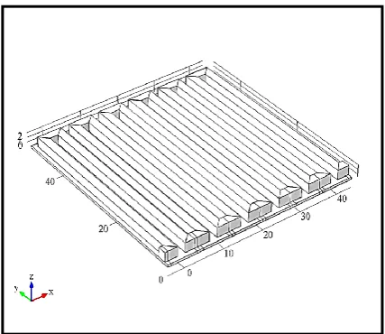
software is used to create and evaluate the complete model of serpentine floe field PEM fuel cell. The entire three dimensional model is shown in figure.1. A fuel cell with 25×25 cm2 reactive area serpentine flow field model square cross-section was considered. In general the PEM fuel cell was consisting of seven layers like membrane, anode and cathode catalyst layers, anode and cathode Gas Diffusion Layers (GDL), anode and cathode flow channels. The entire three dimensional model generation is taking place with the “PEMFC adding domains” in the COMSOL software. By using “forward-looking description domains”, the required modeling terms were produced with respect to the relevant geometry parameters (Thickness, Length, height, width, etc.).
The Cartesian coordinates were used to refer to the whole geometry in the necessary coordinate location. Finally the complete three dimensional model of serpentine flow field PEMFC had been created by reclaiming the data from modeling terms table in the software. Next the different operating parameters like Lumped anode resistance, membrane resistance, Cell temperature, Oxygen reference concentration, GDL Porosity, GDL permeability, membrane conductivity, GDL electric conductivity, Hydrogen molar mass, water molar mass, Oxygen molar mass, inlet mass fraction of H2, inlet mass fraction of O2 and inlet mass fraction of
H2O, inlet velocity, fluid viscosity, Nitrogen molar mass,
water molar mass, Oxygen molar mass, N2-H2O binary
diffusion coefficient, O2-N2 binary diffusion coefficient,
O2-H2O binary diffusion coefficient, reference pressure
and cathodic transfer coefficient were taken into account for the complete numerical analysis on serpentine flow field PEMFC under six cell potentials. The PEMFCs were functioned at a temperature of 50oC and an operating pressure of 1.0 bar respectively.
Figure 1: Serpentine Flow Field PEMFC Model
III.
RESULT AND DISCUSSION
The overall three dimensional serpentine flow fields PEM fuel cell with several modeling modules like membrane, anode and cathode catalyst layers, anode and cathode GDL, anode and cathode flow channels was operated at the similar operating conditions of 60°C temperature and 1.5 bar pressure.
International Journal of Scientific Research in Science and Technology (www.ijsrst.com)
International Journal of Scientific Research in Science and Technology (www.ijsrst.com)
64
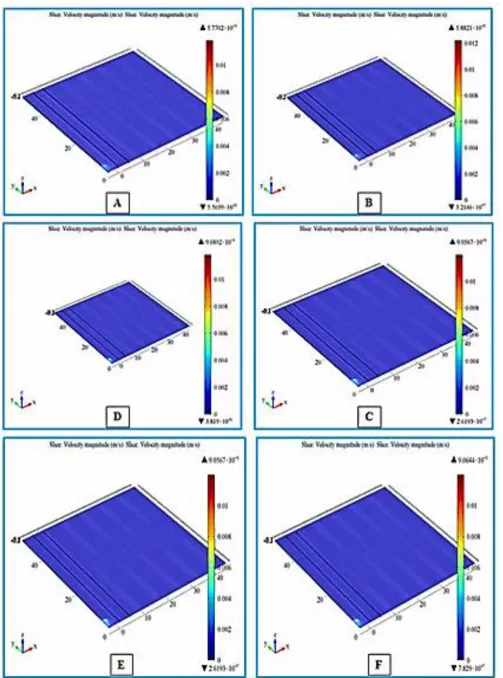
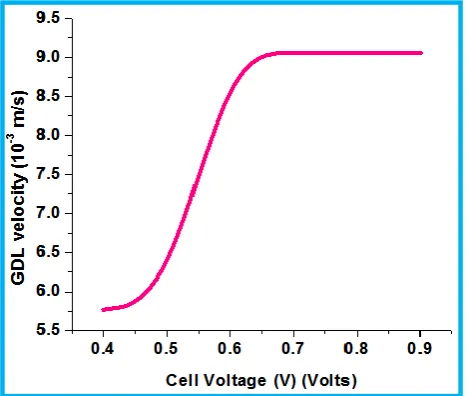
Diffusion Layer of the cell. The amount of GDL velocity distribution of the reactant gases 9.0567m/s was obtained corresponding to the cell potential of 0.7 V at a temperature 50°C. Next the serpentine flow field PEMFC with a cell voltage of 0.8V was engaged and analyzed at the above mentioned operating parameters to evaluate the reactant gases velocity distribution at Gas Diffusion Layer of the cell. The amount of GDL velocity distribution of the reactant gases 9.0567m/s was obtained corresponding to the cell potential of 0.8 V at a temperature 50°C. Next the serpentine flow field PEMFC with a cell voltage of 0.9V was engaged and analyzed at the above mentioned operating parameters to evaluate the reactant gases velocity distribution at Gas Diffusion Layer of the cell. The amount of GDL velocity distribution of the reactant gases 9.0664m/s was obtained corresponding to the cell potential of 0.9V at a temperature 50°C. The effect of GDL velocity distribution of the reactant gases in the serpentine flow field PEMFC for all cell potentials were illustrated in Fig.3in which the different cell potentials (V) were taken in x-axis and the GDL velocity distribution were taken in y-axis.
Figure 3: Gas Diffusion Layer velocity for all cell potentials
IV.
CONCLUSIONS
A numerical analysis has been carried out on a Serpentine Flow Channel PEM Fuel Cell to investigate the adverse Effect of Cell Potentials on Gas Diffusion Layer Velocity and the results were summarized as follows. The highest gas diffusion layer velocity distribution of the reactant gases was found in the cell at
a cell potential of 0.6V. An effective distribution of reactant gases at gas diffusion layer had an adverse impact on the cell performance. The reactant gages velocity distribution at gas diffusion layer inside the cell leads to increases the current density of the entire PEM fuel cell. Therefore, the effective distribution of reactant gases at Gas Diffusion Layer is resulting in higher cell performance especially in the middle cell potentials. This work has demonstrated that velocity distribution of reactant gases inside the cells at middle cell potentials can be used to improve the serpentine flow field PEM fuel cell performance. It was also found that the velocity distribution of the reactant gases at Gas Diffusion Layer indeed improved the cell performances at average cell potentials without modified the operating and design parameters of the serpentine flow channel PEM Fuel cell.
V.
REFERENCES
[1]. Lin Wang, Hongtan Liu, Performance studies of PEM fuel cells with interdigitated flow fields, Journal of Power Sources, Volume 134, Issue 2, 12 August 2004, Pages 185-196.
[2]. A.P. Manso, F.F. Marzo, J. Barranco, X. Garikano, M. Garmendia Mujika, Influence of geometric parameters of the flow fields on the performance of a PEM fuel cell. A review, International Journal of Hydrogen Energy, Volume 37, Issue 20, October 2012, Pages 15256-15287.
[3]. Wei-Mon Yan, Chi-Yen Chen, Sheng-Chin Mei, Chyi-Yeou Soong, Falin Chen, Effects of operating conditions on cell performance of PEM fuel cells with conventional or interdigitated flow field, Journal of Power Sources, Volume 162, Issue 2, 22 November 2006, Pages 1157-1164.
[4]. Xianguo Li, Imran Sabir, Jaewan Park, A flow channel design procedure for PEM fuel cells with effective water removal, Journal of Power Sources, Volume 163, Issue 2, 1 January 2007, Pages 933-942.
[5]. Dilip Natarajan, Trung Van Nguyen,
Three-dimensional effects of liquid water flooding in the cathode of a PEM fuel cell, Journal of Power Sources, Volume 115, Issue 1, 27 March 2003, Pages 66-80.
[6]. Xiao-Dong Wang, Yuan-Yuan Duan, Wei-Mon
International Journal of Scientific Research in Science and Technology (www.ijsrst.com)
65
Power Sources, Volume 175, Issue 1, 3 January 2008, Pages 397-407.
[7]. Andrew Higier, Hongtan Liu, Optimization of PEM fuel cell flow field via local current density measurement, International Journal of Hydrogen Energy, Volume 35, Issue 5, March 2010, Pages 2144-2150.
[8]. Andrew Higier, Hongtan Liu, Direct measurement of current density under the land and channel in a PEM fuel cell with serpentine flow fields, Journal of Power Sources, Volume 193, Issue 2, 5 September 2009, Pages 639-648.
[9]. A.P. Manso, F.F. Marzo, J. Barranco, X. Garikano, M. Garmendia Mujika, Influence of geometric parameters of the flow fields on the performance of a PEM fuel cell. A review, International Journal of Hydrogen Energy, Volume 37, Issue 20, October 2012, Pages 15256-15287.