© 2018 IJSRST | Volume 4 | Issue 2 | Print ISSN: 2395-6011 | Online ISSN: 2395-602X Themed Section: Science and Technology
FPGA Implementation of Single Precision Floating Point Multiplier Using High
Speed Compressors
IM. Lavanya1, A. M. Guna Sekhar2
1M.Tech Scholar, Department of ECE, Sree Rama Engineering College, Tirupathi, Andhra Pradesh, India 2HOD & Associate Professor, Department of ECE,Sree Rama Engineering College,Tirupathi, Aandhra Pradesh, India
ABSTRACT
Floating point multiplier is one of the vital concerns in every digital system. In this paper, the concepts of High speed compressors are used for the implementation of a High speed single precision binary Floating point multiplier by using IEEE 754 standard. Since compressors are special kind of adder which is capable to add more number of bits at a time, the use of these compressors makes the multiplier faster as compared to the conventional multiplier. For Mantissa calculation, a 24x24 bit multiplier has been developed by using these compressors. Owing to these high speed compressors, the proposed multiplier is implemented using Verilog HDL and it is simulated and synthesized for Xilinx 14.3.
Keywords: Floating Point, Multiplication, Single Precision, Verilog HDL.
I.
INTRODUCTION
Multipliers are key components of many high performance systems such as FIR filters, microprocessors, digital signal processors, etc. Multiplication based operations such as multiply and accumulate(MAC) and inner product are among some of the frequently used computation- intensive arithmetic functions currently implemented in many digital signal processing (DSP) applications such as convolution, fast fourier transform(FFT), filtering and in microprocessors in its arithmetic and logic unit. Since multiplication dominates the execution time of most DSP algorithms, so there is a need of high speed multiplier.
Floating point is a way to represent numbers and do arithmetic in computing machines, ranging from simple calculators to computers. The term floating point is derived from the fact that there is no fixed number of digits before and after the decimal point; that is, the decimal point can float. In general, floating-point representations are slower than
fixed-point Representations, but they can handle a larger Range of numbers. The proposed work deals with implementing an architecture for a fast floating point multiplier compliant with the single precision IEEE 754-standard.
The most common representation is defined by the IEEE Standard for Floating-Point Arithmetic (IEEE 754). It is a technical standard established by the Institute of Electrical and Electronics Engineers (IEEE) and the most widely used standard for floating-point computation. Floating Point numbers represented in IEEE 754 format are used in most of the DSP Processors. It also specifies standards for arithmetic operations and rounding algorithms. Floating point arithmetic is useful in applications where a large dynamic range is required or in rapid prototyping applications where the required number range has not been thoroughly investigated.
bits and the Double consist of 64 bits. Floating point number consists of three fields:
1. Sign (S): It used to denote the sign of the number i.e. 0represent positive number and 1 represent negativenumber.
2. Significand or Mantissa (M): Mantissa is part of a floating point number which represents the magnitude ofthe number.
3. Exponent (E): Exponent is part of the floating pointnumber that represents the number of places that thedecimal point (binary point) is to be moved. Number system is completely specified by specifying asuitable base β, significand (mantissa) M, and exponent E.A floating point number F has the value
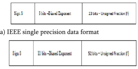
The way floating point operations are executed depends onthe data format of the operands. IEEE standards specify aset of floating point data formats, single precision anddouble precision. The Single precision consists of 32 bitsand the Double precision consists of 64 bits. Figure 1shows the IEEE single and double precision data formats.
(a) IEEE single precision data format
(b) IEEE double precision data format
Figure 1. IEEE Single and Double Precision data Format
The value of the floating point number represented in single precision format is
where 127 is the value of bias in single precision data format and exponent E ranges between 1 to 254, and E =0 and E = 255 are reserved for special values. The value of the floating point number represented in double precision data format is
Where 1023 is the value of bias in double precision dataformat. Exponent E ranges between 1 to 2046, the valuesof E = 0 and E = 2047 are reserved for special values.The performance of multiplier were analyzed using Xilinx ISE simulation tool.
II.
FLOATING POINT MULTIPLIER
ALGORITHM
According to IEEE754 standard, the representation of a 32 bit binary floating point number is consists of sign, exponent and mantissa component. During calculation of floating point multiplication different operations are performed on each component. The detail algorithm is described as below
1. Calculation of the sign bit; i.e. SA XOR SB.
2. Exponent is calculated by adding the exponent of EA and EB. After that, bias the addition by 127 to get the final exponent. i.e. EA+ EB-127.
3. Add 1 before the mantissa bit to make the 23 bit into 24 bit after that multiplies together the 24 bit to get 48 bit result.
4. Normalizing the result, to get the required 23bit mantissa for the final result.
5. Combine the calculated sign, exponent and mantissa components to get the desired multiplication result.
Example of Floating Point Multiplier
Consider two floating point numbers a = -18.0 and b = +9.5
= - 1.00100000000000000000000 x 24 b = +1001.1 = + 00001001.1
= + 1.00110000000000000000000 x 23 sign of a = 1 = s_a
sign of b =0 = s_b
biased exponent of a = 127 + 4 = 131 =10000011 = e_a biased exponent of b = 127 + 3 = 134 =10000010 = e_b mantissa of a = 00100000000000000000000= mant_a mantissa of b = 00110000000000000000000 = mant_b fp_a = 1 10000011 00100000000000000000000 = C1900000h
fp_b = 0 10000010 00110000000000000000000 = 41180000h
Calculation of sign of the product ‘s_out’: s_out = s_axors_b = 1 xor 0 =1
Calculation of exponent of the product ‘e_out’:
Step1: Add e_a and e_b to get the sum 10000011 + 10000010 =1 00000101
Step 2: Bias of 127 is subtracted from the sum to exponent of the output
1 00000101 – 01111111 = 10000110 = e_out Calculation of mantissa of the product ‘m_out’:
Step 1: Extract both the mantissas by adding 1 as MSB for normalization to form 24-bit mantissas
24-bit mant_a = 100100000000000000000000 24-bit mant_b = 100110000000000000000000
Step 2: multiply 24-bit mant_a and mant_b to get 48-bit product
(100100000000000000000000) X (100110000000000000000000)
=01010101100000000000000000000000000000000000 0000
Step 3 : Leading 1 of the 48-bit is found and the remaining bits are truncated to 23-bit output mantissa value to get the mantissa of the output.
m_out = 01010110000000000000000, e_out =100000110
Floating Point Product(in binary) = 1 10000110 01010110000000000000000=C32B0000h
biased exponent = 10000110 =134 unbiased exponent =134 - 127 = 7 Floating Point Product(in decimal) = - 1. 01010110000000000000000x 27
= - 10101011.0000000000000000 = -171 .0
III.
DIFFERENT TYPES OF COMPRESSOR
ARCHITECTURE
In binary multiplication a large number of partial product additions are carried out. In conventional multiplier full adders are used for partial product addition. With full adder maximum of 3 inputs can be added at a time. Accordingly to add all the partial products large numbers of full adders are required. Hence, to reduce the number of adders in this implementation High speed compressors are introduced. Different compressors are developed based upon the concept of binary counter property. A. 5-3 compressor
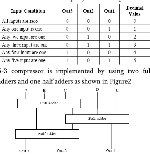
In 5-3 compressor, maximum of five inputs can be added at a time wherein the output is a three bitnumber. Table-1 shows the counter property of 5-3 compressor.
Table 1. Counter Property of 5-3 Compressor
5-3 compressor is implemented by using two full adders and one half adders as shown in Figure2.
B. 4-3 compressor
Some basic different compressors architecture are designed .In Figure. 3 shows the block diagram of 4-3 compressor which is designed by using one full adder and two half adder.
Figure 3. Structural Design of 4-3 Compressor
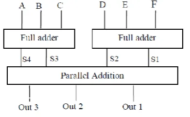
C. 6-3 compressor
For the design of 6-3 compressor, two full adders are used. Figure 4 shows the block diagram of 6-3 compressor. For the parallel addition purpose ripple carry adder as seen in Figure 5 is used.
Figure 4. Structural Design of 6-3 Compressor
Figure 5. Parallel Addition Unit for 6-3 Compressor
D. 7-3 compressor
Similarly for the design of 7-3 compressor in Figure 6, one full adder and one 4-3 compressor are used. Its parallel addition unit is given in figure 7.
Figure 6. Structural Design of 7-3 Compressor
Figure 7. Parallel Addition Unit for 7-3 Compressor
E. 15-4 compressor
For the implementation of 15-4 compressor five full adders, two compressors, and parallel adder unit are used. Figure.8 shows the block diagram of 15-4 compressor and its optimized parallel adder is shown in figure 9.
Figure 9. Parallel Adder Unit for 15-4 Compressor
By using the concept of adders all the compressors are implemented. These compressors are used in the calculation of partial product addition in different stages of binary multiplication.
IV.
SINGLE PRECISION FLOATING POINT MULTIPLIER
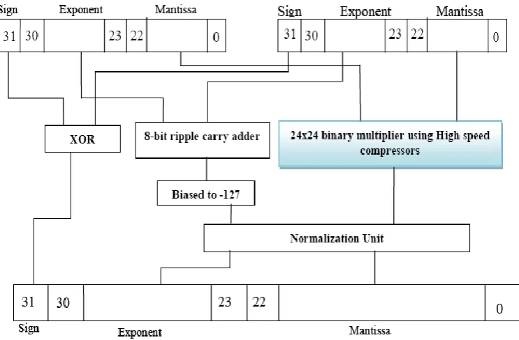
The proposed architecture for Single Precision Floating Point Multiplier using High Speed Compressors is given in Figure 10.
Figure 10. Proposed Architecture of Single Precision Floating Point Multiplier
From the calculation perspective whole floating point multiplication is divided into four sections.
A. Sign section B. Exponent section C. Mantissa section D. Normalization section
A. Sign Section
In sign section, the sign bit for the final result is calculated. The sign bit is calculated by performing XOR operation on the sign bits of the two operands.
B. Exponent Section
In this section the two operands are added directly by using 8-bit ripple carry adder. After addition, biasing is required to get the final exponent. For biasing decimal value 127 is subtracted .Here subtraction is done by using 2’s complement method.
C. Mantissa Section
paper binarymultiplier is implemented by using high speed compressors, which reduces the delay. In single precision floating point number, mantissa is consists of 23 bit. So initially normalization is done in the mantissa by adding 1 at the MSB. After normalization the mantissa of each operand became 24 bit. After binary multiplication of the two normalized 24 bit operands a 48 bit number will generate as a multiplication output. Again this 48 bit number is normalized to 23 bit to get the final mantissa.
In this paper 24 bit multiplier is proposed and implemented by using the concept of high speed compressors. After multiplication of 24x24 binary multiplier large numbers of partial products are obtained. Further those partial products are added by using different compressors at different stage. At first stage of partial product addition, no need of any addition because only one partial product is there. Which directly goes as it is as LSB. At the second stage one half adder is required because only two partial products are here. The sum bit taken as output for that stage and carry will go to the next stage. At third stage, partial products are increased to three and one carry from previous stage and hence a total four partial products are present. Addition of these four partial products is done by using 4-3 compressor. In the next stages the number of partial products goes on increasing. So, higher order compressors are required for addition. Similarly in the4th stage 7-3 compressor, 5thstage 8-4 compressor, 6th stage 9-4 compressor, and 7th stage 10-4 compressor are used. As the stage increases higher order compressors are used. At 24th stage, partial products are increased 28 including the carry from previous stages. For the partial addition of 24th stage 28-5 compressor is used. After 24th stage number partial products are decreasing .So for the addition of those partial products previously used compressors are used.
D. Normalization Section
In the Normalization section, normalization of exponent and mantissa are performed. According to the 47th bit (result of the 24x24 bit binary multiplier) normalization is done.
i. When 47th bit of 24X24 bit binary multiplier is binary one ,mantissa is normalized to 23 bit by taking 46th to 24th bit position number and exponent is increased by decimal value one. ii. When 47th bit of 24X24 bit binary multiplier is
binary zero, mantissa is normalized to 23 bit by taking 45th to 23th bit position number and there is no increment in the exponent value.
V.
RESULTS
The program is written in Verilog code for the implemented single precision floating point multiplier and the results are verified. The simulation results and synthesized results are shown in Xilinx 14.3.
RTL schematic
Technology schematic
Simulation results
VI.
CONCLUSION
In this paper, single precision floating point multiplier based on the IEEE-754 format is successfully implemented on FPGA. The modules are written in Verilog HDL to optimize implementation on FPGA.
VII.
REFERENCES
[1]. A. Dandapat, S. Ghosal, P. Sarkar, D. Mukhopadhyay, "A 1.2-ns16×16-Bit Binary Multiplier Using High Speed Compressors", International Journal of Electrical and Electronics Engineering, 2010.
[2]. Shubhajit Roy Chowdhury, Aritra Banerjee, Aniruddha Roy, HiranmaySaha,"Design, Simulation
[3]. and Testing of a High Speed Low Power 15-4 Compressor for High Speed Multiplication [4]. B. Jeevan, S. Narender, Dr C.V. Krishna Reddy,
Dr K. Sivani,"A High Speed Binary Floating
Point Multiplier Using Dadda
Algorithm",IEEE,2013.
[5]. LoucasLouca, Todd A. Cook, William H. Johnson, "Implementation of IEEE Single Precision Floating Point Addition and Multiplication on FPGAs", IEEE,1996.
[6]. Shaifali, Sakshi, " FPGA Design of Pipelined 32-bit Floating Point Multiplier", International Journal of Computational Engineering & Management, Vol. 16, 5th September 2013. [7]. IEEE 754-2008, IEEE Standard for
Floating-Point Arithmetic, 2008.
[8]. Mohamed Al-Ashrafy, Ashraf Salem, WagdyAnis, "An Efficient Implementation of Floating Point Multiplier", IEEE, 2008.
[9]. Guy Even, Silvia M. Mueller, Peter-Michael Seidel," A dual precision IEEE floating-point multiplier", INTEGRATION the VLSI journal, pp167-180, 2000.
[10]. M. Morris Mano, "Digital Design",3rd edition,