Technical white paper
HP Gen8 Client Virtualization Enterprise
Reference Architecture for VMware View 5.1
Table of contents
Executive summary
3
Client Virtualization and HP
3
Reference Architecture overview
3
Core design
3
Understanding the HP Client
Virtualization Reference Architecture
for VMware View
3
Building block
9
Reference Architecture components
10
HP BladeSystem
10
HP ProLiant Servers
10
HP Storage
11
HP Virtual Connect Flex-10
15
HP 12500 Switch Series
16
HP Thin Clients
17
VMware View
17
Building a proof of concept
18
Proof of concept descriptions
20
Building the proof of concept
22
Create and configure accelerated
storage
24
Scaling the proof of concept
30
Expansion
30
HP and VMware – better together
34
Summary
35
Appendix A – Server sizing
35
Appendix B – Bill of Materials
40
Appendix C – Storage patterning and
For more information
52
Executive summary
This paper outlines HP’s recommended approach to Client Virtualization with VMware and outlines the hardware and software needed as well as the process to create a 480 user proof of concept or pilot implementation of the HP Reference Architecture. The document also discusses the process of scaling the infrastructure to a 4800 user implementation.
Target audience: This document is intended for IT decision makers as well as architects and implementation personnel who want to better understand HP’s approach to Client Virtualization. This and other documents pertaining to Client Virtualization with HP may be found at hp.com/go/cv.
This white paper describes testing performed in March and April of 2012.
Client Virtualization and HP
An increasingly global and mobile workforce is changing the way IT needs to support the business. Worker demographics are also changing, resulting in different expectations on how IT delivers data and applications.
In the old world, Microsoft® Windows® applications and devices are tethered to the desktop; and managing these for a distributed workforce is increasingly challenging. In the new world with collaboration, technologies such as eLearning and unified communications are transforming how users work. However, the bottom line for IT is while they must embrace desktop transformation to enable workers to access their data on many different devices, anywhere and anytime, IT must also protect user information in the data center, not on the device.
Many companies are exploring Bring Your Own Device (or BYOD) strategies to lower their desktop costs and increase employee productivity. While this may lower the costs of purchasing desktops and laptops, the challenges of securely managing these multi-OS devices require a new model that works for both the end user and IT.
Rather than try to meet the needs of this new business paradigm with an old computing model, many companies have found a much simpler, more flexible and secure solution: virtualize the desktop.
HP and VMware make this important move to Client Virtualization safe and easy by testing and developing the most popular solutions. On its sixth generation Client Virtualization reference architecture, HP tests many combinations of storage, networking, and blades to best handle the Client Virtualization workloads.
Reference Architecture overview
Core design
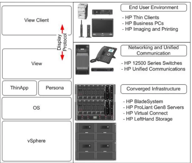
The HP Client Virtualization Reference Architecture for VMware View 5.1 integrates the software, hardware, network communications and management functionality necessary to provide an outstanding, cost-effective end-user experience. HP provides an end-to-end VDI infrastructure including servers, storage, networking and access devices. And HP provides all of the lifecycle services to design, implement and manage the VDI solution.
Understanding the HP Client Virtualization Reference Architecture for
VMware View
VMware View as a method of implementing Virtual Desktop Infrastructure (VDI) is one possible deployment scenario of the Client Virtualization (CV) Reference Architecture. Blade Workstations and server based computing also fit the CV model. With VMware View, a desktop is created as a virtual machine. Applications and user personality are injected into the core desktop virtual machine and a brokering mechanism manages connecting end users to the VM via a connection protocol.
Figure 1. VMware View on the HP CV Reference Architecture overview of software and hardware.
More than simply a virtual machine, what HP refers to, independent of the Client Virtualization solution, as the runtime VDI instance is the real time compilation of the end user’s data, personal settings and application settings with a core operating system instance and shared generic profile where the applications are either installed locally as a fully installed or packaged instance or streamed from outside the VM. While seemingly complex at first glance, the proper management of these individual pieces yields a far more flexible end user computing environment that is simpler to manage. This is accomplished in part by the decoupling of the user and application from the core operating system. A single OS image with few applications is easy to manage as part of an overall, comprehensive client management strategy using tools such as HP Client Automation. Once the user and application are segmented from the device, the device itself starts to matter less as well. With the right approach, an end user can receive the same experience regardless of what core compute resource they are logged onto at the moment. This also means that changing the OS layer is greatly simplified making tasks like Windows operating system migrations simpler for users who have been virtualized. Figure 2 highlights the compute device at runtime in more detail.
Figure 2. The VDI runtime instance
This computing resource becomes available to end users in a variety of locations including branch offices, work from home and outsourced workers. Local users are of course a given. The compute resource thus becomes another resource that resides on the network core. Figure 3 highlights the overall architecture at a high level.
Figure 3. VDI within the overall enterprise
Figure 4 shows the architecture from the network perspective. There are four networks that must be considered when utilizing the HP architecture. The first is the Internet itself which enables off campus users to access a compute resource. The second is the production WAN/LAN to enable users to achieve a compelling end user experience as well as insure that applications and authentication mechanisms are delivered. A management network is also in place to support the management of the hardware via a variety of mechanisms including HP Integrated Lights-Out (iLO). Finally, a storage network is defined to allow communication between iSCSI initiators and targets. One of the key differentiators for this architecture when compared against other offerings is the emphasis on network flexibility and cost for the core of the environment. This is accomplished by migrating as much of the infrastructure and compute resource as possible to within the Virtual Connect domain. This eliminates or minimizes the need for switch ports, allows for the management of intra-domain traffic by a single infrastructure administrator and improves performance and reliability by utilizing cable free internal connections between hosts and management services when possible.
If we look at the previous figure (Figure 4), it is clear that Virtual Connect plays a critical role in the overall architecture. Figure 5 is a closer view of how traffic flows and is segmented between the server and the core. Of particular note is the minimized number of uplinks. A Virtual Connect domain is cabled directly to the core with a minimal number of cables while maintaining required bandwidth and availability. This eliminates the need for rack switches which not only saves cost, but also greatly simplifies the management of the network. In the figure below, production traffic and
management traffic that need to reach the network core are sent via shared uplinks. Of equal interest are the internal networks created. These networks, labeled storage and special function in the figure below, traverse between enclosures but never egress the Virtual Connect domain and thus never touch core network infrastructure. In a VDI environment where numerous teams may need to interact simply to keep the environment up and running it can be difficult to manage the various levels of interactions. The internal storage and special function networks can reduce or even eliminate involvement from the storage and network teams. This in turn centralizes ownership of the solution stack and increases flexibility. One final note is that every ProLiant BL460c Gen8 server blade is equipped with at least two (2) onboard 10Gb Flex-NICs each allowing for the creation of up to four (4) redundant networks of variable bandwidth between 100Mb and 10Gb.
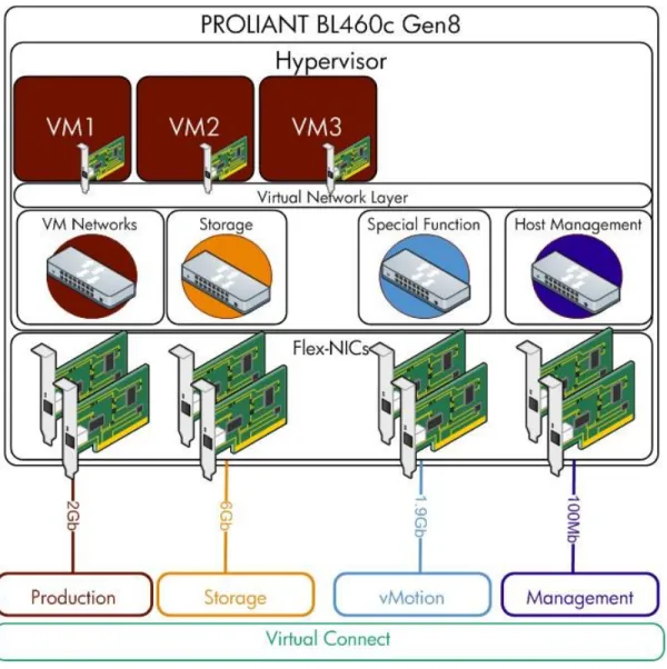
In the context of VMware View, there is an additional layer that must be comprehended. Within VMware View
environments, each host communicates through an abstracted virtual networking layer that allows the individual View and management VMs to communicate with the production network as well as the individual hosts to transmit traffic to storage, be managed and make use of any special function networks. Figure 6 highlights the relationship between the server, hypervisor, virtual machines, virtual networking layer, Flex-NICs and Virtual Connect.
Figure 6. Virtual networking stack from Flex-NIC through to the virtual machine
For more information about VMware View on HP Client Virtualization products and solutions, consult the documentation at hp.com/go/cv.
Building block
Whether hosting a 100 user proof of concept or a 20,000 user production implementation, the building block of the HP Reference Architecture for Client Virtualization remains the same. Figure 7 highlights the components of this building block as part of a 1200 user1 implementation.
Figure 7. 1200 user building block for the reference architecture.
Reference Architecture components
HP BladeSystem
Drive business innovation and eliminate sprawl with HP BladeSystem, the industry’s only Converged Infrastructure architected for any workload from client to cloud. HP BladeSystem is engineered to maximize every hour, watt, and dollar, saving up to 56% total cost of ownership over traditional infrastructures2.
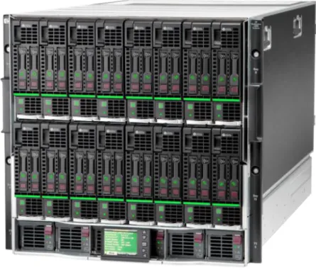
With BladeSystem, it is possible to create a change ready, power efficient, network optimized, simple to manage and high performance infrastructure on which to build and scale your VMware View implementation. An HP BladeSystem c7000 enclosure populated with HP ProLiant BL460c Gen8 blades is shown in figure 8.
Figure 8. The HP BladeSystem c7000 enclosure (pictured with HP ProLiant BL460c Gen8 server blades)
Benefits for VMware View: HP BladeSystem allows for the use of high scaling, distributed 2-socket servers in VMware View implementations while maintaining a minimal amount of infrastructure to be managed. The result is a highly available, power efficient, simple to manage infrastructure set that sacrifices nothing while delivering optimized costs, converged storage and networking, and simple scalability.
HP ProLiant Servers
Choosing a server for VMware View involves selecting a server that is the right mix of performance, price and power efficiency with the most optimal management. HP’s experience during test and in production has been that 2 socket servers are the ideal platform for VMware View. With the possibility of over 100 VMs running on one platform, 2 socket
HP ProLiant BL460c Gen8
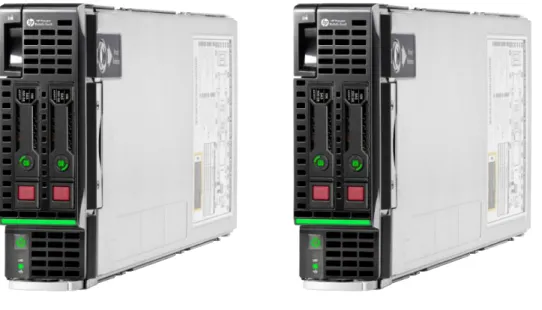
The HP ProLiant BL460c Gen8 is a dual-socket server blade engineered for unprecedented performance, enhanced flexibility and simplified management which makes it a standard for data center computing. Compared to previous generations, the ProLiant BL460c Gen8 Server packs in more performance with a 33 percent increase in memory DIMM count, Intel® Xeon® E5-2600 Processors with added support for 130W processors, faster I/O slots and an enhanced Smart Array Controller that ships with 512MB Flash Back Write Cache standard. In addition, it is also more flexible with the HP FlexibleLOM which provides the ability to customize server networking today and the ability to meet future needs without overhauling server hardware.
Figure 9. HP ProLiant BL460c Gen8
Benefits for VMware View: The BL460c Gen8 is an ideal platform for all CV user types. The BL460c offers not only high user counts per host, but also incredible density which is far more important in optimizing power and management efficiency as well as reducing infrastructure. It also makes no compromises with memory speed which plays an important role over capacity when achieving maximum performance. In addition, the BL460c Gen 8 also offers:
User inspired design features that anticipate your needs and virtually eliminate common issues that result in downtime with features such as the HP SmartDrive carriers and SmartSocket guide.
Integrated Lifecycle Automation, an industry first, provides embedded provisioning tools, Active Health monitoring, and system maintenance capabilities standard on all ProLiant Gen8 servers and built using the industry-leading HP iLO Management Engine.
Automated Energy Optimization improves the server’s ability to analyze and respond to “3D sea of sensors” data within the server as well as self-identify location and inventory through HP Insight Control for maximum workload optimization across the entire data center.
HP Storage
Storage is a critical architectural component of your Client Virtualization deployment. The storage infrastructure is directly in the critical path for hundreds or thousands of your end users and this introduces a number of unique challenges with respect to delivering consistently high performance, minimizing management and deployment costs, and providing scalability and efficient capacity utilization. For this reason, the storage platform you choose is critical to making the economics of Client Virtualization work while maintaining high quality of service levels to satisfy user requirements. HP provides storage solutions to meet small to large Client Virtualization deployments with a range of SAN, NAS and DAS solutions.
HP LeftHand Storage Solutions — ideal storage for Client Virtualization
HP LeftHand Storage solutions are highly optimized for virtual server and desktop environments, with a storage architecture that enables non-disruptive linear scaling of capacity and performance so you can grow your Client Virtualization solution as you need, when you need. With a wide range of storage solution deployment options – from a virtual SAN appliance to rack and blade systems – HP LeftHand Storage provides the optimal mix of storage affordability with the right set of features and scalability to meet your Client Virtualization storage needs, no matter how small or large. HP LeftHand Storage for Client Virtualization delivers:
Storage Efficiency to Maximize Your Client Virtualization Investment: – Thin provisioning raises storage utilization and efficiencies – Clustering, density, and storage tiers optimize dollars per I/O
High Performance to Enable Worker Productivity:
– Clustered, virtualized architecture delivers maximum disk utilization – Dense spindle count, high-speed storage paths, optimized use of SSDs
High Availability to Support Critical End User Applications:
– No single-point-of-failure storage architecture through Network RAID – Non-disruptive software upgrades
Wide Ranging Scalability to Grow When You Need:
– Linear, non-disruptive capacity and performance scaling – Protect your capital investment, start small and grow large For more information, see hp.com/go/lefthand
HP LeftHand P4800 Storage Solutions for HP BladeSystem
The HP LeftHand P4800 Storage Solution delivers storage that is fine-tuned for Client Virtualization with HP BladeSystem. It is based on a tight integration with HP BladeSystem and offers a highly dense storage solution that dynamically and linearly scales as the infrastructure expands. Being converged into the HP BladeSystem architecture enables simplified administration, improved security, flexibility, and enhanced performance through network convergence of the virtual server and storage fabric using 10Gig Ethernet and Flex-10 Virtual Connect.
Simplicity and performance are enhanced with high-speed storage paths, and dense disk spindle counts, all without external storage switching fabric required. All storage software features are included with HP LeftHand Storage, including thin provisioning, snapshots, remote copy, and Network RAID for high availability. Convergence with the HP BladeSystem architecture also provides a significant density and footprint advantage further saving costs. HP P4800 Storage for BladeSystem is designed for departmental or enterprise environments with greater than 500 users.
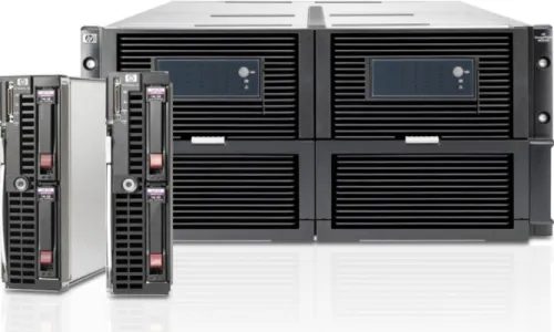
Scaling from 2 nodes and 70 disks (see figure 10) to 8 nodes with 280 disks in a single BladeSystem c7000 enclosure with associated storage drawers, or to 16 nodes with 560 disks across multiple BladeSystem c7000 enclosures and storage drawers ensures I/O performance is outstanding for the large scale VMware View deployments that HP LeftHand P4800 addresses. The ability to make private storage networks where storage traffic remains within the Virtual Connect domain means one administrator can manage the entire infrastructure stack without the need for specialized storage skill sets or in depth network administrator involvement.
Figure 10. The HP LeftHand P4800 Storage Solution for HP BladeSystem
Whether you are looking to place persistent VMs or non-persistent VMs, the HP P4800 offers up the mix of capacity with thin provisioning and performance required for VMware View.
Benefits for VMware View: The convergence of not only storage but also the transport layer into a single, simple to manage infrastructure means intensive multi-team and multi-skill set involvement is a thing of the past. This leads to more rapid deployment and faster response to business-driven change requests. The fact that the fabric is integrated across high speed electrical links leads to performance that is both impressive and scalable, so your users are always productive.
Accelerated storage with HP LeftHand Virtual SAN Appliance Software
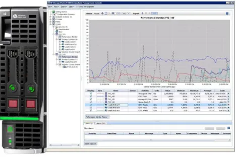
HP provides accelerated storage for VMware View deployments utilizing the management servers that already exist within the enclosure combined with HP IO accelerator mezzanine cards for HP BladeSystem. Figure 11 shows the accelerated storage at a conceptual level.
Figure 11. HP LeftHand Virtual SAN Appliance Software on ProLiant BL460c Gen8
With this approach, at least two management servers are virtualized and a virtual storage appliance is created. This appliance is given control of the IO Accelerator modules. Data written to one appliance is replicated to a second
appliance creating data availability while simultaneously providing scaling. This storage layer scales independently of all other storage layers and storage heads. Like the HP LeftHand P4800 Storage Solutions for HP BladeSystem, the accelerated blade utilizes the Virtual Connect domain communication paths to communicate with initiators resulting in a high speed, low latency storage network that requires no involvement from the storage or network team when
configured to not egress the domain. Replicas and potentially even host swap files can be placed on this storage.
Benefits for VMware View: Utilizing HP LeftHand Virtual SAN Appliance Software (VSA) for selective use as a tiered storage layer in VMware View implementations lowers cost and complexity and allows for right sizing the storage selection at other tiers in terms of cost and performance rather than locking into a single storage platform for all tiers. VSA is even managed from the same console as the other HP LeftHand storage tiers and scales simply to meet demand. The end user experience is always optimized when the replicas are fixed on an ultra-high performance shared storage layer.
User data storage
Data centers today rely on a variety of storage solutions to support different networks, applications and users. Flexibility and scalability are key to meeting these various and often changing requirements. HP X3800 G2 Network Storage Systems meet the requirements of any size data center. For example, the HP X3800 G2 Network Storage Gateway, a network-attached storage (NAS) appliance, with Windows Storage Server 2008 R2, provides large data centers the performance, flexibility and scalability they need to support tens of thousands of users. Figure 12 shows the X3800 G2.
Figure 12. HP X3800 Network Storage Gateway
Benefits for VMware View: The HP X3800 Network Storage Gateway integrates into existing Microsoft Windows management processes and when connected to expandable, scalable storage such as HP LeftHand creates a highly available repository for end user data. This brings user data into data center backup plans while keeping management simple.
HP Virtual Connect Flex-10
VMware View and Flex-10 technology
HP Virtual Connect Flex-10 technology creates a dynamically scalable internal network architecture for VMware View deployments. Multiple c7000 enclosures make up the core building blocks of the physical infrastructure. Each enclosure contains two Virtual Connect (VC) Flex-10 interconnect modules. Each module connects to two dual port 10Gb Flex-10 adapters in each server. Each Flex-10 adapter has four FlexNICs on each of its dual ports. The multiple FlexNICs can support the iSCSI storage, specialized virtual machine function, management, and production networks recommended by HP for VMware View deployments.
VC 10 modules and adapters aggregate Ethernet and accelerated iSCSI storage traffic between the server and Flex-10 module (server-network edge) into a Flex-10Gb link. Flex-Flex-10 technology partitions the Flex-10Gb data stream into multiple (up to four) adjustable bandwidths, preserving routing information for all data classes.
Flex-10 modules and stacking
You can link the Flex-10 modules within each enclosure, and between enclosures, using the internal links available in each enclosure, and using stacking cables and appropriately configured ports on each module. This multi-enclosure stacking creates a single Virtual Connect domain between all the enclosures (up to four enclosures). This means that all HP BladeSystem servers and the P4800 SAN operate in the same VC domain.
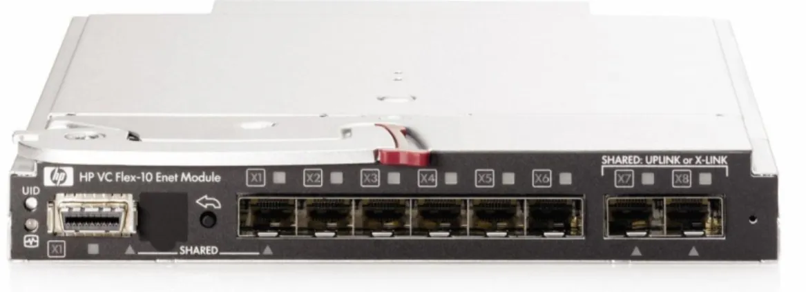
The ability to consolidate all server/storage-side traffic on a single internal VC network, is a major advantage. Any network adapter can connect with any other adapter within the VC network (domain) without exiting to the external network, and without additional switches or network management. This simplifies management, reduces support requirements and a tremendous reduction in both uplink and switch ports. Figure 13 shows a Virtual Connect Flex-10 module.
Benefits for VMware View
Network isolation – Flex-10 technology provides physical network isolation for required network types. VM traffic within the server has access to eight FlexNICs per dual port Flex-10 adapter (four FlexNICs per port).
Network aggregation – The Flex-10 adapter aggregates each set of four FlexNICs into a single 10Gb uplink so that each dual port adapter has only two 10Gb links between the server adapter and the Flex-10 module. From the enclosure or Virtual Connect domain to the core, as few as two cables aggregate networks you choose to egress straight to the core resulting in a dramatic reduction in cables as well as expensive switch ports.
Single internal network – You can stack Flex-10 modules within the enclosure and between enclosures to create a single internal VC network (domain), eliminating the need for additional switches and greater intervention by network administrators, and in the case of the P4800 G2 SAN Solutions for BladeSystem, storage administrators.
Unified management – The Onboard Administrator, Virtual Connect Enterprise Manager and LeftHand Centralized Management Console reduce and simplify the management burden for VMware View administrators. Management and monitoring of the core pieces can be surfaced into your virtualization management software to further simplify the management picture.
HP 12500 Switch Series
When implemented with HP Virtual Connect, the 12500 series switch (see figure 14) facilitates direct wiring to the core saving switch ports, cables and complexity while flattening the network within the data center. The resultant loss in switch ports, cables and management translates directly to lower costs, greater security through the reduction in access points and tremendous performance. Necessary services such as Active Directory, email and application delivery are immediately accessible.
Figure 14. HP 12500 Switch Series
HP Networking has published an overarching reference architecture to help customers understand the implementation and design requirements as well as the benefits of making the shift to industry standard based networking. Consult the Datacenter Network Reference Architecture at http://h20195.www2.hp.com/V2/GetDocument.aspx?docname=4AA3-4150ENW.
HP Thin Clients
Figure 15. HP Flexible Thin Client Portfolio
Flexible Thin Clients
Fast, flexible, secure. Give your business what it deserves. Our engineers did the hard work to develop a smart design with feature-rich power, so you can focus on what matters for you. We know key to growth is staying flexible. We are by your side to help make those growing pains less painful. We have designed our Flexible Thin Clients with the security you need now (and the security you’ll need in the future), with options to grow and expand, all with performance as if you were on a PC.
HP t610 Flexible Thin Client
HP recommends the t610 for your VMware View implementation. Offering out of the box support for VMware View, the t610 provides the ultimate user experience with up to quad display support. AMD’s APU technology combined with dual core processors with AMD HD graphics delivers a more powerful, flexible user experience.
Thin clients are secure by nature, but we made top-level security a priority to make sure your data is even more secure. Our HP t610 is the first thin client to offer both BIOS security and on-board TPM chip, a cryptographic security chip that ensures only the people you authorize will have access to your network. You have the peace of mind of knowing that it meets National Institute of Standards and Technology (NIST) security recommendations.
For more information on our portfolio and to order this product, please visit http://www8.hp.com/us/en/hp-information/thin-client-solutions/thin-client-hardware-software.html.
VMware View
Deploy desktops faster. Migrate and upgrade operating systems and applications quickly and with less downtime. Built on the industry’s leading platform – vSphere, VMware View allows IT to streamline desktop and application
management and securely deliver desktops as a service to users from a central location with levels of availability and reliability unmatched by traditional PCs. Processes are automated and efficient, data is secure and operational expenses are reduced by as much as 50%.
And because this solution ties desktop environments to user identities not devices, end users are free to access their data and applications from any qualified device whether in the office or half way around the world. View with persona management ensures that the user’s familiar desktop appears across devices and locations with everything in the right place, with all authorized applications, files, and data available, and with everything functioning as expected. View with PCoIP further delivers end users a seamless experience across the LAN and WAN to improve workplace mobility and drive higher levels of productivity.
Building a proof of concept
This section of the document walks an installer or group of installers through the process of configuring the hardware for a proof of concept or production implementation capable of supporting 480 medium workload users as described in Appendix A of this document while also providing appropriate system resources to accommodate system failures, HA failover and all management VMs. Total user count will vary based on a number of factors including image size, level of image optimization, deployment methodology, application mix and delivery method, per user I/O footprint and number of servers implemented. Appendix B is a Bill of Materials for the equipment described in this section.
Proof of concept overview
Figure 16 provides a rack level view of the proof of concept described in this section. Cable diagrams elsewhere in this document clearly highlight the minimal number of cables at the rack level and thus the lack of a need for rack switches.
Figure 17 provides a view of the entirety of the cabling required to implement this proof of concept as well as the speed of the network transmission. The HP 12500 series switch in the diagram resides at the core distribution layer of the network. The installer may, at their discretion, choose to further segment out networks. This in turn may introduce more cables. Traditionally this has involved adding 1Gb copper or fibre uplinks to the Virtual Connect modules to facilitate the physical isolation of the management network from the other networks.
Figure 17. Network and SAS cabling required for the proof of concept.
Proof of concept descriptions
The following sections lay out the components required for a proof of concept or production implementation as well as how to physically deploy and provision them.
Physical deployment
The installer should first rack and cable all equipment per HP best practices outlined in the individual product
documentation and figures 16 and 17 in this document. Cable selection to the HP 12500 switch layer should be based on customer standards for physical media.
It should be noted that ordering the HP LeftHand P4800 SAN for BladeSystem with a factory integrated part number will result in the hardware arriving in a much more configured form. This is the recommended option for ordering and is reflected in the bill of materials in Appendix B of this document.
Table 1 represents a bay by bay placement of each component in the proof of concept (POC). A device bay (D) refers to the bays on the front of the c7000 enclosure that hold servers and storage. These bays are numbered left to right and top to bottom with the top row being labeled bays 1 through 8 and the bottom row labeled bays 9 through 16. An interconnect bay (I) refers to the numbered bays in the rear of the c7000 enclosure that handle I/O communication for the environment. The Onboard Administrator bays are assumed to be filled with redundant OAs and are not listed in the table.
Table 1. Device by bay and function
Bay Device Function
D1 HP ProLiant BL460c Gen 8 Hosts core management VMs and optional end user computing VMs
D2 HP ProLiant BL460c Gen 8 Hosts end user computing VMs
D3 HP ProLiant BL460c Gen 8 Hosts end user computing VMs
D9 HP ProLiant BL460c Gen 8 Hosts core management VMs and optional end user computing VMs
D10 HP ProLiant BL460c Gen 8 Hosts end user computing VMs
D11 HP ProLiant BL460c Gen 8 Hosts end user computing VMs
D7 HP P4460sb Storage Blade Storage controller one for the HP LeftHand P4800 SAN for BladeSystem
D8 HP P4460sb Storage Blade Storage controller two for the HP LeftHand P4800 SAN for BladeSystem
I1 HP Virtual Connect Flex-10 Module Master storage and Ethernet traffic communication modules
I2 HP Virtual Connect Flex-10 Module Redundant storage and Ethernet traffic communication modules
I5 HP 3Gb/s SAS Switch SAS link for the HP LeftHand P4800 SAN for BladeSystem
System configurations
vSphere host systems should be configured as follows to insure best functionality within the overall proof of concept environment. Processors with a lower clock speed may be selected, but a reduction in performance should be expected. Memory speed is critical. Slower memory, even of greater capacity, tends to result in lower user counts per server.
Management hosts – Device bays 1 and 9
HP ProLiant BL460c Gen8 with 2 Intel Xeon E5-2680 2.70GHz 8-Core processors, 256GB of Dual Rank x4 PC3-12800 1600MHz memory with VMware ESXi 5.0 Update 1 installed on 300GB SAS Hot Plug with Smart Drive SFF Enterprise Drives and a single 785GB HP IO Accelerator.
View desktop hosts – Device bays 2, 3, 10 and 11
HP ProLiant BL460c Gen8 with 2 Intel Xeon E5-2680 2.70GHZ 8-Core processors, 256GB of Dual Rank x4 PC3-12800 1600MHz memory with VMware ESXi 5.0 Update 1 installed on supported internal flash media or USB disk. No disk drives are needed for these systems
Infrastructure assumptions
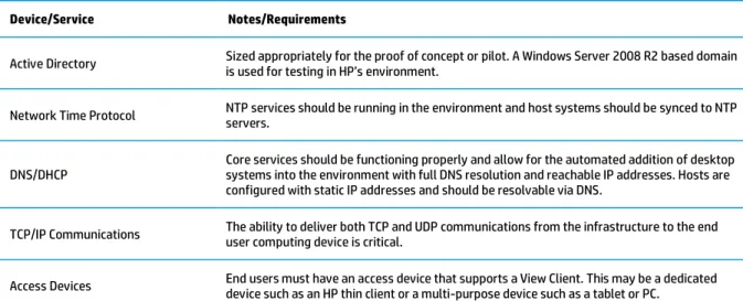
This document assumes that the services and devices listed in table 2 are in place within the proof of concept environment and have been configured according to the best practices of their manufacturers.
Table 2. Devices and services required for the proof of concept
Device/Service Notes/Requirements
Active Directory Sized appropriately for the proof of concept or pilot. A Windows Server 2008 R2 based domain is used for testing in HP’s environment.
Network Time Protocol NTP services should be running in the environment and host systems should be synced to NTP servers.
DNS/DHCP Core services should be functioning properly and allow for the automated addition of desktop systems into the environment with full DNS resolution and reachable IP addresses. Hosts are configured with static IP addresses and should be resolvable via DNS.
TCP/IP Communications The ability to deliver both TCP and UDP communications from the infrastructure to the end user computing device is critical.
Access Devices End users must have an access device that supports a View Client. This may be a dedicated device such as an HP thin client or a multi-purpose device such as a tablet or PC.
Hardware and software versions
Table 3 defines the virtual machine configurations used with the management systems within the proof of concept. Note that disk sizes are what HP tested with. Your image size should be factored into the final configuration. The HP LeftHand Failover Manager is not listed as it requires no reconfiguration after deployment.
Note that these configurations support the proof of concept. Larger capacity virtual machines may be needed if the proof of concept will be grown beyond the boundaries defined in this document.
Table 3. Management VM configuration information
Virtual Machine Function Operating System vCPU/vCore Memory Disk Size
View 5.1 Connection Server 1 Microsoft Windows Server 2008 R2 SP1 Datacenter 4 10GB 40GB
View 5.1 Connection Server 2 Microsoft Windows Server 2008 R2 SP1 Datacenter 4 10GB 40GB
vCenter 5.0 Update 1/
View Composer 3.0 Microsoft Windows Server 2008 R2 SP1 Datacenter 4 8GB 50GB
View Transfer Server Microsoft Windows Server 2008 R2 SP1 Datacenter 2 8GB 40GB
SQL Server (vCenter) Microsoft Windows Server 2008 R2 SP1 Datacenter 2 8GB 60GB
SQL Server (HP SIM) Microsoft Windows Server 2008 R2 SP1 Datacenter 2 8GB 80GB
SQL Server (View Composer) Microsoft Windows Server 2008 R2 SP1 Datacenter 2 8GB 60GB
HP Systems Insight Manager 7 (SIM)/ LeftHand Centralized Management Console
Microsoft Windows Server 2008 R2
SP1 Datacenter 2 8GB 60GB
HP LeftHand VSA 1 HP SAN/iQ 9.5 4 2GB NA
HP LeftHand VSA 2 HP SAN/iQ 9.5 4 2GB NA
Note
HP tested with SQL Server 2008 Enterprise edition. Check the documentation for each of the available components requiring a database for information on supported versions.
Building the proof of concept
This section outlines the steps required to prepare the hardware and software for a proof of concept. It assumes the hardware has been cabled and configured per the previous section.
The steps covered include:
Configure the Onboard Administrator
Update SAS switch and MDS firmware
Update and configure Virtual Connect Flex-10
Install the Virtual Infrastructure
Install and configure View
Build the base image
Configure Onboard Administrator
Prior to any extensive configuration the installer should log onto the active Onboard Administrator (OA) using the username Administrator and the password from the tag on the OA. The following steps in table 4 should be completed prior to proceeding.
Table 4. Onboard Administrator configuration steps
Step Configuration Goal
Change Administrator password Improve overall security
Add new administrative user Eliminate the need to use the default Administrator account for logons. Once created you should log off and log back on using the new administrative account before proceeding.
Configure EBIPA Configure IP addresses for all device and interconnect bays on the enclosure prior to accessing any iLOs or other resources.
Configure NTP Configure NTP server(s) for the enclosure.
Firmware update Update the enclosure firmware to version 3.32 or above if necessary.
Configure Device Power Sequence Configure the Delay for device bays 7 and 8 to 300 seconds. Set other device bays to 360 seconds. Configure Interconnect bays 5 and 6 for a 180 second delay. Configure Interconnect bays 1 and 2 for a 240 second delay.
Update SAS switch and MDS firmware
Always use the latest versions of firmware available for these products.
Update and configure Virtual Connect Flex-10
Prior to beginning the configuration of the Virtual Connect domain, you will need to download the latest firmware for Virtual Connect as well as the Virtual Connect Support Utility, version 1.6 or greater. Use the tool to install the firmware prior to logging onto the VC modules for the first time. You will need to have the administrative and network information for the enclosure and the VC modules convenient to complete this process.
Once completed, carry out the following steps to configure Virtual Connect for a VMware View proof of concept. This document assumes that multiple networks are available and that 10Gb links carry traffic to the core from the VC modules. In this case, the core is an HP Networking 12508 core switch.
Update blade firmware versions
Firmware should be updated on all ProLiant BL460c Gen8 blade servers prior to proceeding. Do not update the firmware on the P4460sb storage blades in device bays 7 and 8. Use the latest versions of firmware for all components by downloading the latest Service Pack for ProLiant (see
http://h18004.www1.hp.com/products/servers/management/spp/index.html).
Install ESXi 5.0 Update 1 on management hosts
The installation process for ESXi will be different based on the function of the host. Multifunction hosts used for management and desktops (bays 1 and 9 for this build) will have ESXi 5.0 U1 installed on a local RAID array consisting of a pair of 300GB 10K RPM SFF SAS disks. These hosts will support local virtual machines and thus require disk space on the system. All other hosts will be built with ESXi 5.0 U1 on flash card or USB key and no local storage. HP’s image for
To facilitate a swap file for each of the hosts, the shared accelerated storage created later in this section will be used. Configure each host for a static IP address and make sure the hostnames that are configured are resolvable in DNS. Follow your normal security and hardening procedures on these hosts.
Enable NTP client on each host and insure the time is set to your local timezone. Configure networking as per table 5.
Table 5. Network configuration for hosts.
vSwitch/Portgroup Bandwidth Adapters Description
vSwitch0
vmkManagement 100Mb vmNic0, 1 Management network for accessing the host
vSwitch1
vmProduction 2Gb vmNic2, 3 Production traffic to applications and protocols to client
vSwitch2
vmkvMotion 1.9Gb vmNic4, 5 vMotion/DRS traffic
vSwitch3
iSCSI 6Gb vmNic6, 7 iSCSI access for management VM
vmkISCSI_a 6Gb vmNic6, 7 iSCSI communication network
vmkISCSI_b 6Gb vmNic6, 7 Redundant iSCSI communication network
Create the installer VM
You will need to create a temporary virtual machine on local storage on a host within the enclosure. This VM should have remote desktop access enabled on the management network and should also have a network adapter on the private iSCSI network. You will install the latest version of the VMware vSphere client and the HP LeftHand Centralized Management Console into the virtual machine. It is recommended that this VM use either Microsoft Windows 7 Professional or Microsoft Windows Server 2008 R2 as the operating system.
You will destroy this VM in a later section once the permanent management infrastructure has been configured.
Create and configure accelerated storage
In order to create shared, accelerated storage, your management hosts must first have HP IO Accelerator modules installed and active within the system. Insure that these cards are active and visible under storage within VMware vCenter.
Install the Failover Manager (FOM) and accelerated storage
When done, login to each VSA and FOM using the VMware vSphere console for the VM and validate that the IP addresses you configured are correct.
For more information, download the HP P4000 VSA Installation and Configuration Guide from
http://bizsupport1.austin.hp.com/bc/docs/support/SupportManual/c03041804/c03041804.pdf.
Configure the SAN
Configure the P4800 by logging on to each P4460sb storage node via iLO remote console and entering IP address information for the node.
Launch the HP LeftHand Centralized Management Console and perform a find using either the addresses you entered on each host or via the IP range/subnet of the private storage network. You must be on a system such as the HP SIM/CMC VM that has access to the private storage network inside the enclosure.
Once discovered, create a management group. Add all P4460sb nodes, VSAs and the FOM to this management group. You will create two clusters. The first is an accelerated storage cluster for the VSAs. Do not create any volumes. Give the cluster a virtual IP. The second cluster will be created with the P4460sb nodes and will also be given a virtual IP. From within the vSphere client of each host, configure the iSCSI storage adapter of each host. Record each IQN and enter it as a server from within the LeftHand CMC.
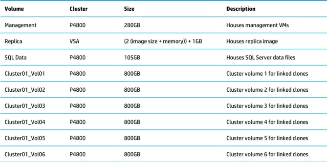
For the proof of concept, create the following volumes as per table 6. Make all volumes thin provisioned.
Table 6. LeftHand SAN volumes by cluster for proof of concept
Volume Cluster Size Description
Management P4800 280GB Houses management VMs
Replica VSA (2 (image size + memory)) + 1GB Houses replica image
SQL Data P4800 105GB Houses SQL Server data files
Cluster01_Vol01 P4800 800GB Cluster volume 1 for linked clones
Cluster01_Vol02 P4800 800GB Cluster volume 2 for linked clones
Cluster01_Vol03 P4800 800GB Cluster volume 3 for linked clones
Cluster01_Vol04 P4800 800GB Cluster volume 4 for linked clones
Cluster01_Vol05 P4800 800GB Cluster volume 5 for linked clones
Cluster01_Vol06 P4800 800GB Cluster volume 6 for linked clones
It should be noted that the number of volumes and their size is based on certain assumptions around the frequency of recomposes as well as the size of the master image. From an HP point of view, a single SAN volume may support between 64 and 100 linked clones. The number selected for this document was 80. The image size used for this test was 28GB and included locally installed applications. HP chose to base volume sizing on an aggressive recompose model that would limit growth of the clones to around 35% of the size of the master image. Following VMware best practices for persona management, application deployment and VM optimization will help to insure reasonable clone growth and optimal solution manageability and may reduce the growth associated with clones over time.
From within the LeftHand CMC attach the replica volume to all hosts. Attach the management and SQL Data volumes to the hosts in bays 1 and 9. Attach the volumes beginning with Cluster01 to the hosts in bays 2, 3, 10 and 11. Figure 18 highlights the relationship between the VMware clusters, hosts, storage and volumes.
Figure 18. Storage volumes and their relationships to other entities.
For more detailed configuration information and a more in depth look at best practices, please consult the HP P4000 LeftHand SAN Solutions with VMware vSphere Best Practices guide at
http://h20195.www2.hp.com/V2/GetDocument.aspx?docname=4AA3-6918ENW. You will configure the storage VMs to be tied to a given host in later sections.
Deploy Management VMs
Download the HP Systems Insight Manager Installation and Configuration Guide for Windows from
http://bizsupport2.austin.hp.com/bc/docs/support/SupportManual/c02786423/c02786423.pdf.
The second VM that the installer will need to create is the SIM / LeftHand CMC virtual machine. Once the operating system is installed and patched and security hardening practices have been implemented the installer should install the following software in the order listed.
HP LeftHand Centralized Management Console version 9.5
HP LeftHand Command Line IQ (CLIQ)
HP Systems Insight Manager 7.0
Follow the instructions for each piece of software as referenced below and in the links at the end of this document. Reboot the VM as needed to complete the process. It is required that you are able to start a remote desktop session to this virtual machine from the management network in order to facilitate the setup and configuration of the HP LeftHand storage.
Documents needed for this section include the following:
HP Systems Insight Manager 7.0 Installation and Configuration Guide for Microsoft Windows which may be downloaded with HP Systems Insight Manager at
http://h18006.www1.hp.com/products/servers/management/hpsim/index.html
HP P4000 Command-Line Interface User Guide
http://bizsupport1.austin.hp.com/bc/docs/support/SupportManual/c03041974/c03041974.pdf
HP P4000 SAN Solution User Guide found at
http://bizsupport1.austin.hp.com/bc/docs/support/SupportManual/c03035314/c03035314.pdf
Once the software has been installed and you have verified connectivity to the VM as well as the SAN you may destroy the original installer VM and begin using this virtual machine as the central point of management for the proof of concept.
The third and fourth VMs to be created will be SQL Server virtual machines that will house the databases for VMware vCenter 5.0 U1 and VMware View Composer 3.0. Follow VMware’s instructions on configuring these SQL instances for the respective pieces of software. Links to documentation for VMware View and associated components are located at
vmware.com/technical-resources/products/view.html.
The fifth virtual machine to be installed will be for VMware vCenter 5.0 U1. Follow VMware’s instructions for installing vCenter. It is recommended that you also install View Composer on this virtual machine for the proof of concept or pilot implementation. If your intent is to move to a larger scale production environment using the infrastructure and VMs created for the proof of concept or pilot build then you should create a separate VM to install View Composer.
Note
When purchasing View Premier from HP you are entitled to run vCenter 5.0 U1 for Desktops as a VM under the same licenses as you use for View. It is recommended that you keep a separate vCenter instance for your View implementation using this license rather than consuming any existing VMware licenses.
The sixth and seventh VMs will create a redundant View Manager configuration by creating two View VMs. Consult VMware’s View documentation at vmware.com/technical-resources/products/view.html for installation instructions.
Deploy the View desktop hosts
Install VMware ESXi 5.0 Update 1 to flash media or internal USB key on the remaining servers (bays 2, 3, 10 and 11). Configure networking using VMware vCenter or the vSphere Client as in table 7. You may choose to configure the networking for the cluster as a distributed virtual switch. It is highly recommended that you leave the management network a standard vSwitch.
Table 7. Network configuration for hosts.
vSwitch/Portgroup Bandwidth Adapters Description
vSwitch0
vmkManagement 100Mb vmNic0, 1 Management network for accessing the host
vSwitch1
vmProduction 2Gb vmNic2, 3 Production traffic to applications and protocols to client
vSwitch2
vmkvMotion 1.9Gb vmNic4, 5 vMotion/DRS traffic
vSwitch3
iSCSI 6Gb vmNic6, 7 iSCSI access for management VM
vmkISCSI_a 6Gb vmNic6, 7 iSCSI communication network
Configure the virtual infrastructure
To configure VMware properly you will need to create a default Datacenter and one cluster from within VMware vCenter. For the purposes of a proof of concept, a single cluster is okay provided you remain within the maximums specified by VMware for number of hosts in a cluster (currently 8 hosts when utilizing View Composer). Insure that you assign the VSA VMs and the View Manager VMs to a specific pair of hosts (bays 1 and 9). These VMs should not be affected by Distributed Resource Scheduler (DRS) or High Availability (HA) and should remain tied to these hosts. Management VMs and End User Computing VMs should be placed into separate Resource Pools within the cluster. Figure 18 shows the relationships to the hardware and storage volumes. These entities will all reside within one Datacenter. Figure 19 below highlights the Datacenter, cluster and Resource Pools as they relate to the virtual machines.
Figure 19. Datacenter and clusters within the proof of concept.
Install and configure View
Consult the VMware View documentation from VMware to insure you are following best practices for your particular situation. View documentation may be found at vmware.com/technical-resources/products/view.html. In particular and at a minimum, the installer should become completely familiar with the following documents.
VMware View 5 Architecture Planning, available at vmware.com/support/pubs/view_pubs.html
VMware View 5 Performance and Best Practices, available at vmware.com/files/pdf/view/VMware-View-Performance-Study-Best-Practices-Technical-White-Paper.pdf
VMware ThinApp Reference Architecture, available at vmware.com/files/pdf/thinapp-ref-arch.pdf
vmware.com/files/pdf/view/VMware-View-Antivirus Practices for VMware View 5 Best Practices, available at vmware.com/files/pdf/techpaper/VMware-View-AntiVirusPractices-TN-EN.pdf
Build the base image
To insure you are following best practices for image optimization in VMware View environments, download and read the VMware View Optimization Guide for Windows 7 at vmware.com/files/pdf/VMware-View-OptimizationGuideWindows7-EN.pdf.
Scaling the proof of concept
Expansion
Growing each building block into a large scale implementation may take one of two approaches. The approaches are outlined below along with a set of general benefits and drawbacks to aid in the decision making process about what approach to take.
Network expansion
The HP approach to Client Virtualization results in a flatter network stack which dramatically simplifies the expansion of the network as your CV implementation grows. Cable connections as well as network ports are minimized while maintaining needed bandwidth.
The core of the expansion capabilities comes from the HP 12500 core switch. Rather than a multi-layer switch design with expensive ports at the rack, edge and core, the design of HP’s reference architecture utilizes Virtual Connect Flex-10 Ethernet modules to facilitate direct inter and intra-enclosure communication replacing both rack and edge switch infrastructure. Outbound management and production network traffic are connected directly to the core for the lowest possible latencies and flattest possible network.
As an enclosure is brought online during the expansion process, the Virtual Connect Ethernet modules are cable connected together to create a Virtual Connect domain. Up to four enclosures or approximately 4500 productivity users are capable of transferring network information to each other at 10Gb/s speeds with no switch.
Either a single enclosure or each enclosure within the domain may have uplinks defined to the core. These uplinks are customizable and may be as small in size as a 1Gb/s redundant network or as large as multiple 10Gb/s connections per network. These outbound connections carry end user data and connections as well as management traffic straight to the core.
SAN expansion
There are two ways to expand the SAN as your implementation grows. This document outlines the benefits and drawbacks to each. It is as the installers discretion as to which one to use.
Single SAN scaling as shown in figure 20 is the first method for growth. With this method, more nodes are added to the existing management group and LeftHand cluster until the limits of the cluster are reached or, as in figure 20, until the boundaries of the rack are reached. This scales the existing SAN to a higher storage and I/O capacity while minimizing targets for hosts. This approach works well for monolithic implementations where large numbers of similar users are hosted in a single location and serve a similar function.
In figure 20 below this equates to two separate, 8 node P4800 SANs, each of which is in the same management group but comprises a different cluster (these could also be combined into one large 16 node cluster). These SANs may be configured to communicate across all enclosures and servers (see Virtual Connect section above), as individual targets dedicated to a given rack, or where desired, as a large multi-site SAN or distributed cluster where data is replicated between racks.
Figure 20. 4800 single SAN scaling method.
Native building block growth is the second method for SAN growth and is shown in figure 21. In this approach, the native building block shown in figure 7 is used and simply repeated. It is however repeated while building out a larger Virtual Connect domain to keep all storage traffic within the bounds of domain and off of the external networks.
With this approach, each SAN is its own cluster. It is generally simpler from a management standpoint to keep all clusters within one management group and assign hosts to targets as needed until the maximums for the management
The drawback to this approach is data segmentation across multiple clusters. This approach is recommended when there are distributed groups with clearly delineated functions. For example, if you have 8 separate groups with a broad range of user counts that will be served by your infrastructure, distributing risk across the 4 building blocks may make more sense than placing all users inside a larger, more monolithic building block. Data segmentation with this arrangement would be less of an issue.
Figure 22 below shows the Virtual Connect cabling for both of the above expansion options. All eight modules are interconnected creating a low latency, 10Gb redundant path from any one enclosure to another within the domain. This insures that all traffic, such as storage traffic to the P4800, that occurs between systems in the domain does not egress. This results in a dramatic reduction in cabling as well as port costs and eliminates the need for rack switches associated with View.
Figure 22. Expansion cabling for Virtual Connect modules
Software expansion
handle a failure. Consult the VMware documentation referenced throughout this document paying particular attention to the VMware View 5.1 Architecture Planning, available at vmware.com/support/pubs/view_pubs.html.
HP Systems Insight Manager is implemented to manage and monitor hardware resources, not end user computing VMs. As such, a single instance of SIM can be used from proof of concept to 4800 user implementation and beyond.
Figure 23 shows the layout of one half of the 4800 user expansion from a vCenter point of view. This design is based on the single SAN scaling method shown in figure 20, but both expansion methods are easily adapted. Because all hosts in one rack reside within the same Virtual Connect domain as those in another rack it is simple to distribute clusters across racks rather than within the rack as shown below.
Figure 23. Cluster design for one half of the 4800 user expansion.
This design focuses on minimizing pool and replica counts while maximizing the number of virtual machines in each resource pool. Final design for the placement of virtual machine resources may be altered provided that the design remains within the limits set by VMware in the documents referenced at the end of this paper.
HP and VMware – better together
HP is a VMware Global Technology Alliance Partner across servers, storage, networking and technology services. HP is also a reseller of VMware software. HP and VMware engineering and technical marketing teams work together to certify and integrate joint solutions and produce complete solutions for our customers. HP and VMware enable you to:
Standardize on a common virtualization platform with VMware View, vSphere and HP industry-standard components
Summary
Whichever size proof of concept or pilot is chosen to help facilitate the move to Client Virtualization, this reference architecture white paper outlines the hardware and software needed as well as the processes used to complete a functional implementation.
Appendix A – Server sizing
Measuring server performance in VMware View environments
HP has a longstanding tradition of using its own tools to measure server performance for various approaches to VDI. In the past, these methods have produced reliable numbers that were achievable in real world usage. This greatly helped with planning VDI implementations and setting realistic expectations around costs. There has been a demand for a standardized number that reflects the capacity of a system in addition to a reliable estimation of real world performance.
The industry as a whole has settled on more of a benchmark approach using a small number of tools to approximate system capacity. HP shunned this approach for a period of time as results produced tended to be extremely optimistic and when misused resulted in much higher costs for VDI at implementation time versus estimation time. HP sought a tool that could thus approximate both capacity and real world numbers as well as work across a variety of approaches to both VDI and other forms of server based computing. After examining tools, HP settled on Login VSI.
Login VSI overview
Login VSI is a benchmarking tool designed to measure the performance of centralized desktop environments such as Server Based Computing and Virtual Desktop Infrastructure.
Test environment
All tests were performed on a single HP ProLiant BL460c Gen8 server. Replicas resided on an HP IO Accelerator layer, clones resided on the HP LeftHand P4800 SAN for BladeSystem and the controlling server featured 2 Intel Xeon E5-2680 processors and 256GB of 1333MHz PC10600 RAM. Faster memory is available and recommended as memory speed can be more important than capacity in achieving maximum results. Memory running slower than 1333MHz should not be used. Host cache was used during these tests and set to 2048MB within View.
Virtual machines were optimized following VMware’s recommended procedures. The virtual machines ran Microsoft Windows 7 64-bit. VMs running the light workload were assigned 1.5GB of memory while medium and heavy workload VMs were assigned 2GB of vRAM. All VMs used a single vCPU. A dedicated linked clone model was used for testing and is the basis for this Reference Architecture. The display protocol used was Microsoft Remote Desktop Protocol (RDP). HP recommends sizing your VMs to your application and usage patterns. Assigning the correct amount of memory is one of the easiest ways to optimize performance in a VMware View environment.
User performance, as measured by response times, remains consistent whether the replica is stored on a VSA hosted shared IO Accelerator store or on local IO Accelerators. Since there is no tradeoff in user experience and space is adequate for replica storage, HP recommends the shared IO Accelerator model for availability and large cost reduction as well as reduction in parts.
Workloads
Login VSI offers a number of workloads intended to emulate different user behaviors. To best emulate HP’s traditional test methodology, the medium, light, and heavy user workloads were chosen. These workloads represent productivity, task, and knowledge workers respectively. Login VSI works by providing a series of workloads that may be run against a centralized resource or set of centralized resources. LoginVSI measures a series of predefined timings for actions that occur during these workloads (such as copies, application start times and compressing files). This data is evaluated in terms of number of VSI sessions and a VSIMax score is output as a function of the baseline performance versus the response times of the actions under load.
Detailed information about Login VSI is available at loginvsi.com. In particular, dissemination of how tests are run as well as how scores are calculated is available at loginvsi.com/en/admin-guide.
scripts. The best result of all tests is reported in this document. Prior to the start of any test run the server under test (SUT) is rebooted and all virtual machines are restarted. The SUT is allowed a period of rest to reclaim memory prior to test start. This is generally a 2-3 hour period depending on the number of virtual machines being tested.
HP ProLiant BL460c Gen8 results
Medium workload
The medium workload is frequently used to express user counts that represent general productivity users or “average” end users. HP has chosen to report this workload as being representative of such a user with the caveats listed in the section entitled Real world estimations and recommended sizings. HP strongly recommends consulting that section prior to planning a VMware View proof of concept or production implementation. Figure A-1 highlights the results of the medium workload test.
Using the ProLiant BL460c Gen8 server configured as listed in this document HP received a VSI Max score of 195 users with a medium workload. Response times for actions measured within the script remained very low as shown in the graph below validating the quality of HP’s end user experience.
Light workload
HP suggests the light workload is representative of single function workers or environments where concurrency of use is low. For detailed information on this workload, consult the Login VSI Admin Guide at loginvsi.com/en/admin-guide. Figure A-2 highlights the result of the light workload testing.
Running the light workload with the ProLiant BL460c Gen8 configured as described in this document HP achieved a VSI Max score of 242 users with very fast response times.
Heavy workload
The heavy workload represents workers who place a great deal of pressure on their systems with multiple applications open and heavy interaction on a frequent basis. Figure A-3 highlights the result of the heavy workload test.
Running the heavy workload with the ProLiant BL460c Gen8 configured as described in this document HP achieved a VSI Max score of 164 users with very fast response times on measured script actions.
Baselines
HP has not previously published results using Login VSI on ProLiant systems of G7 and earlier generations. As a point of reference and to establish a baseline, HP is making those results available for the medium user script. The tests were conducted using an HP VirtualSystem CV2 and a ProLiant BL460c G7 with 2 Xeon X5675 processors and 192GB of 1333MHz PC10600 memory. Using this method HP achieved a VSI Max score of 143 medium users as shown in figure A-4 below.
Figure A-4. Baseline results for G7 servers and a medium script workload
This substantiates that the ProLiant BL460c Gen8 has seen a 36% performance increase versus the same server in G7 configuration.
Real world estimations and recommended sizings
Prior to making recommendations it is important to note that the following numbers are just guidelines. While these numbers will be achievable by some customers, others may find numbers that are significantly higher or lower. Adherence to best practices during all aspects of the design and build phases of your VMware View implementation as well as choosing optimized methods for deploying and managing VMs will nearly always result in greater user density. Selecting problematic applications, poorly suited user groups and failing to follow recommendations will nearly always have the opposite effect. This is critical because these densities have a potentially large impact on the acquisition and long term costs of running VMware View in a given environment.
HP recommends the following planning numbers to estimate real world sizing based on the graphs achieved by running Login VSI. These results are ranges that estimate, from the graphs and data obtained from the Login VSI tests, where the user experience begins to change. It has been HP’s experience over many years of working with customers on VDI
Table A-1. Recommended planning numbers by user type.
User Type VSIMax Recommended Range
Medium 195 117-127
Light 242 145-157
Heavy 164 82-90
The sizing for this reference architecture is derived from the medium script load and an estimate of 120 users per server in conjunction with the capabilities of the storage to handle 18 IOPs per user in a 50/50 RW ratio. This storage
requirement is derived from fibre channel traces captured by HP of running VDI environments. Native storage read write ratios in production have a large range of variability. It is important that you understand and assess your individual environment to properly size. Management VMs with the exception of those noted remain within the same set of servers as end user computing resources and will have an effect on overall server sizing. Resources are left available to handle system level failures as well as maintenance tasks.
There are many variables that will have an effect on your overall sizing including proper image optimization, memory speed and architecture, concurrency ratio of active users to total users, application delivery methods, operating system choice, protocol and provisioning methodology. All sizing numbers should be used as guidelines only.
Appendix B – Bill of Materials
Table B-1 represents a bill of materials for the components described in this white paper that allow for the creation of the proof of concept or production implementation. Some regional adjustments may be necessary. Consult your HP sales representative to determine any changes that may be needed. As shown below, this configuration would include racking by HP Factory Express.
Table B-1. Bill of materials for the proof of concept
Line Item QTY Item Number Description
0100 1
1
BW908A BW908A#001
HP 10642G3 1200mm Shock Rack Factory Express Base Racking Complex 1
0200 1
1
507019-B21 507019-B21 0D1
HP BLc7000 CTO 3 IN LCD ROHS Encl Factory Integrated
0201 4
4
641016-B21 641016-B21 0D1
HP BL460c Gen8 10Gb FLB CTO Blade Factory Integrated
0202 4 662063-L21 HP BL460c Gen8 E5-2680 FIO Kit
0203 4
4
662063-B21 662063-B21 0D1
HP BL460c Gen8 E5-2680 Kit Factory Integrated
Line Item QTY Item Number Description
0206 5 647444-B21
647444-B21 0D1
HP4GB Micro SDHC Flash Media Kit Factory Integrated
0207 2 641016-B21
641016-B21 0D1
HP BL460c Gen8 10Gb FLB CTO Blade Factory Integrated
0208 2 662063-L21 HP BL460c Gen8 E5-2680 FIO Kit
0209 2
2
662063-B21 662063-B21 0D1
HP BL460c Gen8 E5-2680 Kit Factory Integrated 0210 32 32 672631-B21 672631-B21 0D1 HP 16GB 2Rx4 PC3-12800R-11 Kit Factory Integrated 0211 4 4 652564-B21 652564-B21 0D1
HP 300GB 6G SAS 10K 2.5in SC ENT HDD Factory Integrated
0212 2 684211-B21 HP Flex-10 10Gb 2P 530FLB FIO Adptr
0213 2 QK762A HP 785GB IO Accelerator 0214 2 AJ864A AJ864A 0D1 HP 3Gb SAS BL-c Switch Factory Integrated 0215 1 591973-B21 591973-B21 0D1
HP VC Flex-10 Ent Edn for BLc7000 Opt Factory Integrated
0216 2 453154-B21
453154-B21 0D1
HP BLc VC1Gb RJ-45 SFP Opt Kit NOTE: This is optional. Factory Integrated
0217 2 455883-B21
455883-B21 0D1
HP BLc 10Gb SR SFP+ Opt NOTE: You may choose a direct cable connection for 10Gb connections. Consult your sales representative. Factory Integrated
0218 1 517521-B22 HP 6X 2400W Plat Ht Plug FIO Pwr Sply Kit
0219 1 456204-B21
456204-B21 0D1
HP BLc7000 DDR2 Encl Mgmt Option Factory Integrated
0220 1 413379-B21 HP BLc7000 1PH FIO Power Module Opt 0221 1 417688-B23 HP c-Class All FIO 16 Icm 1yr 24x7 lic 0222 1 517520-B21 HP BLc 6X Active Cool 200 FIO Fan Opt
0300 1 H4396B HP No Additional Support Required
0400 1
1
433718-B21 413718-B21 0D1
HP BLc7000 10K Rack Ship Brkt Opt Kit Factory Integrated