AT Commands
For GSM/GPRS Wireless
Modems
AT Commands for GSM/GPRS Wireless Modems Reference Guide
Products: MTCBA-G-F1/F2, MTMMC-G-F1/F2, and MTSMC-G-F1/F2 PN S000293C, Revision C
Copyright
This publication may not be reproduced, in whole or in part, without prior expressed written permission from Multi-Tech Systems, Inc. All rights reserved. Copyright © 2003, by Multi-Tech Systems, Inc.
Multi-Tech Systems, Inc. makes no representations or warranties with respect to the contents hereof and specifically disclaims any implied warranties of merchantability or fitness for any particular purpose. Furthermore, Multi-Tech Systems, Inc. reserves the right to revise this publication and to make changes from time to time in the content hereof without obligation of Multi-Tech Systems, Inc. to notify any person or organization of such revisions or changes. Revisions
Revision Level Date Description
A 07/15/03 Initial release.
B 03/08/04 Add Values to each command. Add new commands.
C 09/28/04 Change page 19 data/fax call to ATD<nb>; and voice call to ATD<nb> Change page 93 Autobauding is supported (operating from 2400 to 115200) Trademarks
The Multi-Tech logo is a trademark of Multi-Tech Systems, Inc. World Headquarters
Multi-Tech Systems, Inc. 2205 Woodale Drive
Mounds View, Minnesota 55112 Phone: 763-785-3500 or 800-328-9717 Fax: 763-785-9874
Technical Support
Country By Email By Phone
France: [email protected] (33) 1-64 61 09 81 India: [email protected] 91 (124) 6340778 U.K.: [email protected] (44) 118 959 7774
U.S. and Canada: [email protected] (800) 972-2439 Rest of the World: [email protected] (763) 717-5863 Internet Address: http://www.multitech.com
Contents
Chapter 1 - Introduction ...10
Scope of This Document...10
Related Documents ...10
Definitions ...10
Chapter 2 - AT command Features...11
Line Settings ...11
Command Line...11
Information Responses and Result Codes ...11
Chapter 3 - General be haviors ...12
SIM Card Insertion and Removal Procedures ...12
Background Initialization ...12
Chapter 4 - General AT Commands...13
Manufacturer Identification +CGMI ...13
Request Model Identification +CGMM ...13
Request Revision Identification +CGMR ...13
Product Serial Number +CGSN ...14
Select TE Character Set +CSCS ...14
Phonebook Character Set +WPCS...14
Request IMSI +CIMI...15
Card Identification +CCID ...15
Capabilities List +GCAP...15
Repeat Last Command A/...15
Power Off +CPOF ...15
Set Phone Functionality +CFUN...16
Phone Activity Status +CPAS ...16
Report Mobile Equipment Errors +CMEE ...17
Keypad Control +CKPD ...17
Clock Management +CCLK ...17
Alarm Management +CALA ...18
Chapter 5 – AT Call Control commands ...19
Dial Command D...19
Hang-Up command H ...20
Answer a Call A...21
Remote Disconnection...21
Extended Error Report +CEER ...21
DTMF Signals +VTD, +VTS...22
Echo Cancellation +ECHO...27
SideTone Modification +SIDET...29
Initialize Voice Parameters +VIP ...29
Chapter 6 - Network service commands...30
Signal Quality +CSQ ...30
Operator Selection +COPS...31
Network Registration +CREG ...33
Read Operator Name +WOPN ...34
Selection of Preferred PLMN List +CPLS ...34
Preferred Operator List +CPOL ...35
Read Operator Name +COPN ...37
Chapter 7 - Security commands ...38
Enter PIN +CPIN...38
Enter PIN2 +CPIN2...40
PIN Remaining Attempt Number +CPINC ...40
Facility Lock +CLCK...41
Change Password +CPWD...42
Chapter 8 - Phonebook commands...43
Select Phonebook Memory Storage +CPBS ...43
Read Phonebook Entries +CPBR...44
Find Phonebook Entries +CPBF...44
Write Phonebook Entry +CPBW ...45
Phonebook Phone Search +CPBP ...46
Move Action in Phonebook +CPBN ...46
Subscriber Number +CNUM ...47
Avoid Phonebook Initialization +WAIP...48
Delete Calls Phonebook +WDCP ...48
Set Voice Mail Number +CSVM...49
Chapter 9 - Short Messages Commands ...50
Parameters Definition ...50
Select Message Service +CSMS ...51
New Message Acknowledgement +CNMA ...51
Preferred Message Storage +CPMS ...53
Preferred Message Format +CMGF ...54
Save Settings +CSAS ...54
Restore Settings +CRES ...55
Show Text Mode Parameters +CSDH ...55
New Message Indication +CNMI ...56
Read Message +CMGR...57
List Message +CMGL ...58
Send Message +CMGS ...59
Write Message to Memory +CMGW ...59
Select Cell Broadcast Message Types +CSCB ...62
Cell Broadcast Message Identifiers +WCBM...63
Message Status Modification +WMSC ...63
Message Overwriting +WMGO ...64
Unchange SMS Status +WUSS...65
Chapter 10 – Supplementary Services Commands ...66
Call Forwarding +CCFC...66
Call Barring +CLCK...67
Modify SS Password +CPWD...68
Call Waiting +CCWA...68
Calling Line Identification Restriction +CLIR...69
Calling Line Identification Presentation +CLIP...70
Connected Line Identification Presentation +COLP ...71
Advice of Charge +CAOC ...72
Accumulated Call Meter +CACM ...72
Accumulated Call Meter Maximum +CAMM ...73
Price Per Unit and Currency Table +CPUC...73
Call Related Supplementary Services +CHLD ...74
List Current Calls +CLCC...75
Supplementary Service Notifications +CSSN ...76
Unstructured Supplementary Service Data +CUSD ...77
Closed User Group +CCUG...78
Chapter 11 - Data Commands ...79
Using AT Commands During a Data Connection ...79
Bearer Type Selection +CBST...80
Select Mode +FCLASS ...81
Service Reporting Control +CR ...81
Cellular Result Dodes +CRC ...82
DTE-DCE Local Rate Reporting +ILRR...82
Radio Link Protocol Parameters +CRLP ...83
Other Radio Link Parameters +DOPT ...83
Select Data Compression %C ...84
V42bis Data Compression +DS ...84
V42bis Data Compression Report +DR ...85
Select Data Error Correcting Mode \N ...85
Chapter 12 - Fax Commands...86
Transmit speed +FTM...86
Receive Speed +FRM...86
HDLC Transmit Speed +FTH...86
Transmit Page Punctuation +FET...88
Page Transfer Status Parameters +FPTS ...88
Terminate Session +FK ...89
Page Transfer Bit Order +FBOR...89
Buffer Size Report +FBUF ...89
Copy Quality Checking +FCQ...89
Capability to Receive +FCR...89
Current Sessions Parameters +FDIS ...90
DCE Capabilities Parameters +FDCC ...91
Local ID String +FLID...91
Page Transfer Timeout Parameter +FPHCTO ...91
Fax Class 2 Indication Messages ...92
Chapter 14 – V.24 and V.25 commands ...93
Fixed DTE Rate +IPR ...93
DTE-DCE Character Framing +ICF ...94
DTE-DCE Local Flow Control +IFC ...95
Set DCD Signal &C ...95
Set DTR Signal &D ...96
Set DSR Signal &S ...96
Back to Online Mode O...96
Result Code Suppression Q ...97
DCE Response Format V ...97
Default Configuration Z ...97
Save Configuration &W...97
Auto-Tests &T ...98
Echo E...98
Restore Factory Settings &F...98
Display Configuration &V ...99
Request Identification Information I ...99
Multiplexing Mode +WMUX...100
Chapter 15 - Specific AT commands...101
Cell Environment Description +CCED ...101
General Indications +WIND ...103
Analog Digital Converter Measurements +ADC ...104
Mobile Equipment Event Reporting +CMER...105
Indicator Control +CIND...106
Mobile Equipment Control Mode +CMEC...107
Read Language Preference +WLPR ...107
Write Language Preference +WLPW...108
Read GPIO Value +WIOR ...108
Write GPIO Value +WIOW...109
Input/Output Management +WIOM...109
Voice Rate +WVR ...112
Data Rate +WDR ...112
Select Voice Gain +WSVG ...113
Status Request +WSTR...113
Scan +WSCAN ...114
Ring Indicator Mode +WRIM...114
32kHz Power Down Mode +W32K ...115
Change Default Melody +WCDM...115
Custom Character Set +WCCS ...116
Lock +WLCK ...117
CPHS Command +CPHS ...118
Unsolicited Result: Voice Mail Indicator +WVMI...120
Unsolicited Result: Diverted Call Indicator +WDCI ...120
Network Operator Name +WNON ...121
CPHS Information +WCPI...121
Customer Service Profile +WCSP ...122
Customer Storage Mirror +WMIR ...122
Change Default Player +WCDP...122
CPHS Mail Box Number +WMBN...123
Alternate Line Service +WALS ...124
Open AT Control Command +WOPEN...124
Reset +WRST ...125
Set Standard Tone +WSST ...126
Hang-up +WATH...127
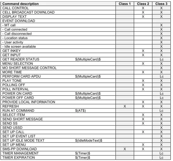
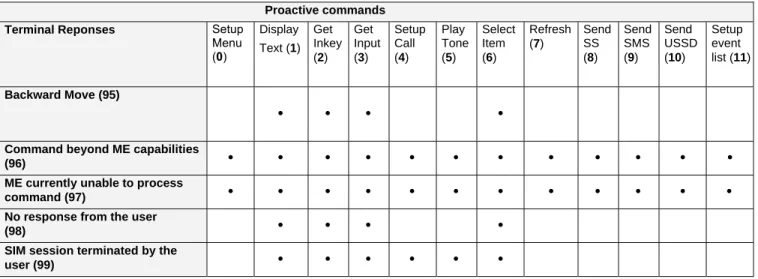
Chapter 16 - SIM ToolKit...128
Overview of SIM Application ToolKit...128
Messages Exchanged During a SIM ToolKit Operation ...130
SIM Toolkit Commands Section...131
SIM ToolKit Set Facilities +STSF...131
SIM ToolKit Indication +STIN...133
SIM ToolKit Get Information +STGI ...134
Unsolicited Result: SIM ToolKit Control Response +STCR...137
SIM ToolKit Give Response +STGR...137
Chapter 17 - GPRS commands ...140
Define PDP Context +CGDCONT ...140
Quality of Service Profile Requested +CGQREQ ...142
Quality of Service Profile Minimum Acceptable +CGQMIN ...144
GPRS Attach or Detach +CGATT...145
PDP Context Activate or Deactivate +CGACT ...146
Automatic Response to a Network Request for PDP Context Activation +CGAUTO...153
Manual Response to a Network Request for PDP Context Activation +CGANS ...154
Show PDP Address +CGPADDR ...155
Cellular Result Codes +CRC ...156
Service Reporting Control +CR ...156
Extended Error Report +CEER ...157
GPRS Parameters Customization +WGPRS...157
Full GPRS AT Command Examples ...158
GPRS-Related Errors +CME ERROR ...159
Specific GPRS Failure Cause for +CEER ...159
Chapter 18 - Other AT commands ...160
V.25ter Recommendation ...160
GSM 07.05 Recommendation...160
GSM 07.07 Recommendation...160
Appendix A – Result Codes, Failure Causes, Other Tables ...161
ME Error Result Code: +CME ERROR: <error>...161
Message Service Failure Result Code +CMS ERROR: <er>...162
Specific Error Result Codes...162
Failure Cause from GSM 04.08 Recommendation (+CEER) ...163
Specific Failure Cause for +CEER...164
GSM 04.11 Annex E-2: Mobile Originating SM-Transfer...164
Unsolicited Result Codes...165
Final Result Codes...165
Intermediate Result Codes ...165
Parameter Storage Mode...166
GSM Sequences List ...168
Operator Names...170
Appendix B - Data Commands and Multiplexing, CPHS Information Field, and CSP Constants...178
Data Commands and Multiplexing ...178
CPHS Information Field ...179
CSP Constants...180
Appendix C - AT Command Examples...182
Examples ...182
Appendix D - ME SIM ToolKit Support ...186
Appendix E - Structure of the Terminal Profile ...188
Appendix F - Command Type and Next Action Indicator...190
Appendix G - Coding of Alpha fields in the SIM for UCS2...191
Appendix H - Specification of Power Down Control via RS232 ...192
Appendix I - Conditions for command execution and SIM dependence ...193
General Commands ...193
Call Control Commands ...193
Network Service Commands ...193
Data Commands ...195
Fax Commands...195
Class 2 Commands...195
V24-V25 Commands...195
Specific AT Commands ...196
SIM ToolKit Commands ...196
C
HAPTER
1
-
I
NTRODUCTION
Scope of This Document
This document describes the AT-command based messages exchanged between an application and the Multi-Tech Systems, Inc. products in order to manage GSM-related events or services.
Related Documents
This interface specification is based on the following recommendations: [1] ETSI GSM 07.05: Digital cellular telecommunications system (Phase 2);
Use of DTE-DCE interface for Short Message Service (SMS) and Cell Broadcast Service (CBS) [2] ETSI GSM 07.07: Digital cellular telecommunications system (Phase 2);
AT command set for GSM Mobile Equipment (ME)
[3] ITU-T Recommendation V.25 ter: Serial asynchronous automatic dialing and control [4] ETSI GSM 03.40: Digital cellular telecommunications system (Phase 2);
Technical implementation of the Short Message Service (SMS) Point-to-Point (PP) [5] ETSI GSM 03.38: Digital cellular telecommunications system (Phase 2);
Alphabets and language-specific information
[6] ETSI GSM 04.80: Digital cellular telecommunications system (Phase 2):
Mobile radio interface layer 3, Supplementary service specification, Formats and coding
Definitions
The words, “Mobile Station” (MS) or “Mobile Equipment” (ME) are used for mobile terminals supporting GSM services.
A call from a GSM mobile station to the PSTN is called a “mobile originated call” (MOC) or “outgoing call”, and a call from a fixed network to a GSM mobile station is called a “mobile terminated call” (MTC) or “incoming call”.
C
HAPTER
2
-
AT
COMMAND
F
EATURES
Line Settings
A serial link handler is set with the following default values (factory settings): autobaud, 8 bits data, 1 stop bit, no parity, RTS/CTS flow control. Please use the +IPR, +IFC and +ICF commands to change these settings.
Command Line
Commands always start with AT (which means ATtention) and finish with a <CR> character.
Information Responses and Result Codes
Responses start and end with <CR><LF>, except for the ATV0 DCE response format and the ATQ1 (result code suppression) commands.
• If command syntax is incorrect, an ERROR string is returned.
• If command syntax is correct but with some incorrect parameters, the +CME ERROR: <Err> or +CMS
ERROR: <SmsErr> strings are returned with different error codes.
• If the command line has been performed successfully, an OK string is returned.
In some cases, such as “AT+CPIN?” or (unsolicited) incoming events, the product does not return the OK string as a response.
C
HAPTER
3
-
G
ENERAL BE HAVIORS
SIM Card Insertion and Removal Procedures
SIM card Insertion and Removal procedures are supported. There are software functions relying on positive reading of the hardware SIM detect pin. This pin state (open/closed) is permanently monitored.
When the SIM detect pin indicates that a card is present in the SIM connector, the product tries to set up a logical SIM session. The logical SIM session will be set up or not depending on whether the detected card is a SIM Card or not. The AT+CPIN? command delivers the following responses:
• If the SIM detect pin indicates “absent”, the response to AT+CPIN? is “+CME ERROR 10” (SIM not inserted).
• If the SIM detect pin indicates “present”, and the inserted Card is a SIM Card, the response to AT+CPIN? is “+CPIN: xxx” depending on SIM PIN state.
• If the SIM detect pin indicates “present”, and the inserted Card is not a SIM Card, the response to AT+CPIN? is CME ERROR 10.
• These last two states are not given immediately due to background initialization. Between the hardware SIM detect pin indicating “present” and the previous results the AT+CPIN? sends “+CME ERROR: 515” (Please wait, init in progress).
When the SIM detect pin indicates card absence, and if a SIM Card was previously inserted, an IMSI detach procedure is performed, all user data is removed from the product (Phonebooks, SMS etc.). The product then switches to emergency mode.
Background Initialization
After entering the PIN (Personal Identification Number), some SIM user data files are loaded into the product (Phonebooks, SMS status, etc.). Please be aware that it might take some time to read a large phonebook. The AT+CPIN? command response comes just after the PIN is checked. After this response user data is loaded (in background). This means that some data may not be available just after PIN entry is confirmed by ’OK’. The reading of phonebooks will then be refused by “+CME ERROR: 515” or “+CMS ERROR: 515” meaning, “Please wait, service is not available, init in progress”.
This type of answer may be sent by the product at several points:
• When trying to execute another AT command before the previous one is completed (before response),
• When switching from ADN to FDN (or FDN to ADN) and trying to read the relevant phonebook immediately,
• When asking for +CPIN? status immediately after SIM insertion and before the product has determined if the inserted card is a valid SIM Card.
C
HAPTER
4
-
G
ENERAL
AT
C
OMMANDS
Manufacturer Identification +CGMI
Description: Displays the manufacturer identification. Values: No parameters
Command syntax: AT+CGMI
Command Possible responses
AT+CGMI
Note: Get manufacturer identification
WAVECOM MODEM OK
Note: Command valid, Wavecom modem
Request Model Identification +CGMM
Description: Displays the supported frequency bands. With multi-band products the response may be a
combination of different bands.
Values: No parameters
Command syntax: AT+CGMM
Command Possible responses
AT+CGMM
Note: Get hardware version
MULTIBAND 900 E 1800 OK
Note: Multiband: GSM 900 MHz extended band and DCS 1800
AT+CGMM
Note: Get hardware version
MULTIBAND G850 1900 OK
Note: Multiband: GSM 850 and PCS
Request Revision Identification +CGMR
Description: Displays the revised software version. Values: No parameters
Syntax: AT+CGMR
Command Possible responses
AT+CGMR
Note: Get software version
640b09gg.Q2406A 1266500 070403 17:06
OK
Note: Software release 6.40b, generated on the 4th of July 2003
Product Serial Number +CGSN
Description: Allows the user application to get the IMEI (Interrnational Mobile Equipment Identity, 15-digit
number) of the product.
Values: No parameters
Syntax: AT+CGSN
Command Possible responses
AT+CGSN Note: Get the IMEI
012345678901234
OK
Note: IMEI read from EEPROM AT+CGSN
Note: Get the IMEI
+CME ERROR: 22
Note: IMEI not found in EEPROM
Select TE Character Set +CSCS
Description: Informs the ME which character set is used by the TE. The ME can convert each character of
entered or displayed strings. This is used to send, read or write short messages. See also +WPCS for the phonebooks’ character sets.
Values: <Character Set>
GSM GSM default alphabet.
PCCP437 PC character set code page 437.
CUSTOM User defined character set (cf. +WCCS command).
HEX Hexadecimal mode. No character set used; the user can read or write hexadecimal values.
Default: GSM alphabet
Syntax: AT+CSCS=<Character Set>
Command Possible responses
AT+CSCS=”GSM”
Note: GSM default alphabet
OK
Note: Command valid AT+CSCS=”PCCP437”
Note: PC character set code OK
Note: Command valid AT+CSCS=?
Note: Get possible values
+CSCS: ("GSM","PCCP437","CUSTOM","HEX") OK
Note: Possible values
Phonebook Character Set +WPCS
Description: Informs the ME which character set is used by the TE for the phonebooks. The ME can convert
each character of entered or displayed strings. This is used to read or write phonebook entries. See also +CSCS for the short messages character sets.
Values: <Character Set>
TRANSPARENT Transparent mode. The strings are displayed and entered as they are stored in SIM or in ME.
CUSTOM User defined character set (cf. +WCCS command).
HEX Hexadecimal mode. No character set used; the user can read or write hexadecimal values.
Syntax: AT+WPCS=<Character Set>
Command Possible responses
AT+WPCS=”TRANSPARENT” Note: Transparent mode
OK
Note: Command valid AT+WPCS=”CUSTOM”
Note: Custom character set
OK
Note: Command valid
Request IMSI +CIMI
Description: Reads and identifies the IMSI (International Mobile Subscriber Identity) of the SIM card. The
PIN may need to be entered before reading the IMSI.
Values: No parameters
Syntax: AT+CIMI
Command Possible responses
AT+CIMI
Note: Read the IMSI
208200120320598 OK
Note: IMSI value (15 digits), starting with MCC (3 digits) / MNC (2 digits, 3 for PCS 1900)
Card Identification +CCID
Description: Orders the product to read the EF-CCID file on the SIM card. Values: No parameters
Syntax: AT+CCID
Command Possible responses
AT+CCID Note: Get card ID
+CCID: “123456789AB111213141”
Note: EF-CCID is present, hexadecimal format AT+CCID?
Note: Get current value
+ CCID: “123456789AB111213141” Note: Same result as +CCID AT+CCID= ?
Note: Get possible value
OK
Note: No parameter but this command is valid
Note: If there is no EF-CCID file present on the SIM, the +CCID answer will not be sent, but the OK message will be returned.
Capabilities List +GCAP
Description: Displays the complete list of capabilities. Values: No parameters
Syntax: AT+GCAP
Command Possible responses
AT+GCAP
Note: Get capabilities list
+GCAP: +CGSM +FCLASS OK
Note: Supports GSM and FAX commands
Repeat Last Command A/
Description: Repeats the previous command. Only the A/ command itself cannot be repeated.
Values: No parameters
Syntax: A/
Command Possible responses
A/
Note: Repeat last command
Set Phone Functionality +CFUN
Description: Selects the mobile station’s level of functionality. When the application wants to stop the
product with a power off, or if the application wants to force the product to execute an IMSI DETACH procedure, then it must send: AT+CFUN=0 (equivalent to AT+CPOF). This command executes an IMSI DETACH and makes a backup copy of some internal parameters in SIM and in EEPROM. The SIM card cannot then be accessed. If the mobile equipment is not powered off by the application after this command has been sent, a re-start command (AT+CFUN=1) will have to issued to restart the whole GSM registration process. If the mobile equipment is turned off after this command, then a power on will automatically restart the whole GSM process. The AT+CFUN=1 command restarts the entire GSM stack and GSM functionality: a complete software reset is performed. All parameters are reset to their previous values if AT&W was not used. If you write entries in the phonebook (+CPBW) and then reset the product directly (AT+CFUN=1, with no previous AT+CFUN=0 command), some entries may not be written (the SIM task does not have enough time to write entries in the SIM card). In addition, the OK response will be sent at the last baud rate defined by the +IPR command. With the
autobauding mode the response can be at a different baud rate, it is therefore preferable to save the defined baud rate with AT&W before directly sending the AT+CFUN=1 command.
Values: <functionality level>
0: Set minimum funtionality; IMSI detach procedure 1: Set the full functionality mode with a complete software reset
Syntax: AT+CFUN=<functionality level>
Command Possible responses
AT+CFUN?
Note: Ask for current functionality level
+CFUN: 1 OK
Note: Full functionality AT+CFUN=0
Note: Set minimum functionality, IMSI detach procedure
OK
Note: Command valid AT+CFUN=1
Note: Set the full functionality mode with a complete software reset
OK
Note: Command valid
Phone Activity Status +CPAS
Description: Returns the activity status of the mobile equipment. Values: <pas>
0 ready (allow commands from TA/TE) 1 unavailable (does not allow commands)
2 unknown
3 ringing (ringer is active) 4 call in progress
5 asleep (low functionality)
Syntax: AT+CPAS
Command Possible responses
AT+CPAS
Note: Current activity status
+CPAS: <pas> OK
Report Mobile Equipment Errors +CMEE
Description: Disables or enables the use of the “+CME ERROR: <xxx>” or “+CMS ERROR:<xxx>” result
code instead of simply “ERROR”. See Appendix A for +CME ERROR result codes description and +CMS ERROR result codes.
Values: <error reporting flag>
0: Disable ME error reports; use only ERROR
1: Enable +CME ERROR: <xxx> or +CMS ERROR: <xxx> Syntax: AT+CMEE=<error reporting flag>
Command Possible responses
AT+CMEE=0
Note: Disable ME error reports, use only ERROR
OK AT+CMEE=1
Note: Enable +CME ERROR: <xxx> or +CMS ERROR: <xxx>
OK
Keypad Control +CKPD
Description: Emulates the ME keypad by sending each keystroke as a character in a <keys> string. The supported GSM sequences are listed in the Appendix A.
If emulation fails, a +CME ERROR: <err> is returned. If emulation succeeds, the result depends on the GSM sequence activated: <keys>: string of the following characters (0-9,*,#). Note: In the case where the FDN phonebook is activated, the sequences concerning “call
forwarding” are allowed only if the entire sequence is written in the FDN. Values: <keys>
Keyboard sequence; sting of the following characters (0-9, *, #) Syntax: AT+CKPD=<keys>
Command Possible responses
AT+CKPD=”*#21#”
Note: Check every call forwarding status
+CCFC: 0,7 AT+CKPD=”1234”
Note: Sequence not allowed
+CME ERROR 3
Clock Management +CCLK
Description: Sets or gets the current date and time of the ME real-time clock. Values: <date and time string>
String format for date/time is “yy/MM/dd,hh:mm:ss”
Note: Valid years are 98 (for 1998) to 97 (for 2097). The seconds field is not mandatory. Default date/time is “98/01/01,00:00:00” (January 1st, 1998 / midnight).
Syntax: AT+CCLK=<date and time string>
Command Possible responses
AT+CCLK=”00/06/09,17:33:00” Note: set date to June 9th
, 2000, and time to 5:33pm
OK
Note: Date/Time stored AT+CCLK=”00/13/13,12:00:00”
Note: Incorrect month entered
+CME ERROR 3 AT+CCLK?
Note: Get current date and time
+CCLK: “00/06/09,17:34:23” OK
Note: current date is June 9th , 2000
Alarm Management +CALA
Description: Sets the alarm date/time in the ME. The maximum number of alarms is 16.
Values: <date and time string> String format for alarms: “yy/MM/dd,hh:mm:ss” (see +CCLK) Note: Seconds are taken into account.
<index> Offset in the alarm list, range 1 to 16 Syntax: AT+CALA=<date and time string> (set alarm)
AT+CALA=””,<index> (delete alarm)
Command Possible responses
AT+CALA=”00/06/09,07:30”
Note: set an alarm for June 9th
, 2000 at 7:30 am
OK
Note: Alarm stored AT+CALA=”99/03/05,13:00:00”
Note: set an alarm for March 5th
, 1999 at 1:00 pm
+CME ERROR 3
Note: Invalid alarm (date/time expired) AT+CALA?
Note: list all alarms
+CALA: “00/06/08,15:25:00”,0 +CALA: “00/06/09,07:30:00”,1 +CALA: “00/06/10,23:59:00”,2
Note: three alarms are set (index 0, 1, 2) +CALA: “00/06/08,15:25:00”,0
Note: an alarm occurs (index 0) AT+CALA=””,2
Note: delete alarm index 2
OK
Note: Alarm index 2 deleted AT+CALA?
Note: list all alarms
+CALA: “00/06/09,07:30:00”,1 Note: Only one alarm (index 1)
C
HAPTER
5
–
AT
C
ALL
C
ONTROL COMMANDS
Dial Command D
Values: <nb> Destination phone number
<I> Optional parameter <I> means “invocation” (restrict CLI presentation) <i> Means “suppresssion” (allow CLI presentation)
<mem> Phonebook (one of SM, LD, MC, ME, RC, MT or SN). A default value can be selected by +CPBS command.
<index> Call number at indicated offset from the phonebook selected by the +CPBS command.
<name> Call number corresponding to given name from the phonebook selected by the +CPBS command.
Description: The ATD command sets a voice, data or fax call. As per GSM 02.30, the dial command also
controls supplementary services.
For a data or a fax call, the application sends the following ASCII string to the product (the bearer must
be previously selected with the +CBST command):
ATD<nb> where <nb> is the destination phone number;
For a voice call, the application sends the following ASCII string to the product: (the bearer may be
selected previously, if not a default bearer is used).
ATD<nb>; where <nb> is the destination phone number.
Please note that for an international number, the local international prefix does not need to be set (usually 00) but does need to be replaced by the ‘+’ character.
Example: to set up a voice call to Multi-Tech offices from another country, the AT command is: “ATD+17637853600;”
Note that some countries may have specific numbering rules for their GSM handset numbering. The response to the ATD command is one of the following:
Verbose result code
Numeric code (with ATV0 set)
Description
OK 0 if the call succeeds, for voice call only
CONNECT <speed> 10,11,12,13,14,15 if the call succeeds, for data calls only, <speed> takes
the value negotiated by the product.
BUSY 7 If the called party is already in communication
NO ANSWER 8 If no hang up is detected after a fixed network time-out
NO CARRIER 3 Call setup failed or remote user release. Use the
AT+CEER command to know the failure cause
Direct Dialing from a Phonebook (stored in the SIM card) can be performed with the following commands:
ATD> <index>; to call <index> from the selected phonebook (by the +CPBS command) ATD> “BILL”; to call “BILL” from the selected phonebook
ATD> mem <index> (mem is SM, LD, MC, ME, RC, MT or SN, see +CPBS command) allows
Syntax: ATD<nb>[<I>][;]
ATD>[<mem>]<index>[<I>][;] ATD>[<mem>]<name>[<I>][;]
Command Possible responses
AT+CPBS?
Note: Which phonebook is selected ?
+CPBS:”SM”,8,10
Note: ADN phonebook is selected, 8 locations are used and 10 locations are available
ATD>SM6;
Note: Call index 6 from AND phonebook
OK
Note: Call succeeds
When the FDN phonebook has been locked, only numbers beginning with the digits of FDN phonebook entries can be called. For example, if “014629” is entered in the FDN phonebook all the phone numbers beginning with these 6 digits can be called. The CLIR supplementary service subscription can be overridden for this call only.
“I” means “invocation” (restrict CLI presentation). “i” means “suppression” (allow CLI presentation).
Control of CUG supplementary service information by “G” or “g” is allowed for this call only. The index and info values set with the +CCUG command are used. An outgoing call attempt could be refused if the AOC service is active and credit has expired (NO CARRIER). When trying to set up an outgoing call while there is an active call, the active call is first put on hold, then the call set up is carried out. As per GSM 02.30, GSM sequences may be controlled using dial commands. These sequences can contain “*”, “#”, but “;” is forbidden. If the sequence is not supported or fails, +CME ERROR: <err> is returned. In the case where the FDN phonebook is activated, the sequences concerning call forwarding are allowed only if there are written in the FDN.
Command Possible responses
ATD*#21#
Note: Check any call forwarding status
+CCFC: 0,7
Note: No call forwarding ATD**61*+33146290800**25#
Note: Register call forwarding on no reply, with no reply timer fixed at 25 s.
OK Note: done ATD*2#
Note: Bad sequence
+CME ERROR 3
Hang-Up command H
Description:
The ATH (or ATH0) command disconnects the remote user. In the case of multiple calls, all calls are released (active, on-hold and waiting calls). The specific ATH1 command has been appended to disconnect the current outgoing call, only in dialing or alerting state (ie. ATH1 can be used only after the ATD command, and before its terminal response (OK, NO CARRIER, ...). It can be useful in the case of multiple calls.
Values:
<n>
0: Ask for disconnection (default value) 1: Ask for outgoing call disconnection
Syntax: ATH<n>
Command Possible responses
ATH
Note: Ask for disconnection
OK
Note: Every call, if any, is released ATH1
Note: Ask for outgoing call disconnection
OK
Answer a Call A
Description:
When the product receives a call, it sets the RingInd signal and sends the ASCII “RING” or “+CRING:
<type>” string to the application (+CRING if the cellular result code +CRC is enabled). Then it waits for the
application to accept the call with the ATA command. Syntax: ATA
Command Possible responses
RING
Note: Incoming call ATA
Note: Answer to this incoming call
OK
Note: Call accepted ATH
Note: Disconnect call
OK
Note: Call disconnected
Remote Disconnection
This message is used by the product to inform the application that an active call has been released by the remote user.
The product sends “NO CARRIER” to the application and sets the DCD signal.
In addition, for AOC, the product can release the call if credit has expired (release cause 68 with +CEER command).
Extended Error Report +CEER
Description:
This command gives the cause of call release when the last call set up (originating or answering) failed. Values: No parameters
Syntax: AT+CEER
Command Possible responses
ATD123456789;
Note: Outgoing voice call
NO CARRIER
Note: Call setup failure AT+CEER
Note: Ask for reason of release
+CEER: Error <xxx> OK
Note: <xxx>is the cause information element values from GSM recommendation 04.08 or specific Call accepted
DTMF Signals +VTD, +VTS
+VTD Description:
The product enables the user application to send DTMF tones over the GSM network. This command is used to define tone duration (the default value is 300ms). To define this duration, the application uses:
AT+VTD=<n> where <n>*100 gives the duration in ms. If n < 4, tone duration is 300 ms. +VTD Values:
<n> tone duration.
*100 is the duration in ms. If < 4, tone duration is 300 ms; if n > 255, the value used is modulo 256. Default value: 300 ms, that is <n> = 3.
+VTD Syntax: AT+VTD=<n>
Command Possible responses
AT+VTD=6
Note: To define 600 ms tone duration
OK
Note: Command valid AT+VTD=0
Note: To set the default value
OK
+VTS Description:
The product enables the user application to send DTMF tones over the GSM network. This command enables tones to be transmitted only when there is an active call.
To transmit DTMF tones (only when there is an active call), the application uses: AT+VTS=<Tone>
where <Tone> is in {0-9,*,#,A,B,C,D} +VTS Values:
<Tone> DTMF tone to transmit. Tone is in {0-9, *, #, A, B, C, D} +VTS Syntax: AT+VTS=<Tone>
Command Possible responses
AT+VTS=A OK
Note: Command valid AT+VTS=11
Note: To set the default value
+CME ERROR: 4
Note: If the <Tone> is wrong
AT+VTS=4 +CME ERROR: 3
Note: If there is no communication Example:
To send tone sequence 13#, the application sends: AT+VTS=1;+VTS=3;+VTS=#
OK
Redial Last Telephone Number DL
Description:
This command redials the last number used in the ATD command. The last number dialed is displayed followed by “;” for voice calls only.
Values: No parameters
Syntax: ATDL
Command Possible responses
ATDL
Note: Redial last number
0146290800; OK
Automatic Dialing with DTR %D
Description:
This command enables and disables:
• Automatic dialing of the phone number stored in the first location of the ADN phonebook, • Automatic sending of the short message (SMS) stored in the first location of the SIM.
The number is dialed when DTR OFF switches ON. The short message is sent when DTR OFF switches ON. Values:
<n> Enable or disables automatic message transmission or number dialing.
Informs the product that the number is a voice rather than a fax or data number.
0 Disables automatic DTR number dialing / message transmission.
1; Enables automatic DTR dialing if DTR switches from OFF to ON; Dials the phone number in the first
location of the ADN phonebook. Voice call.
1 Activates automatic DTR dialing if DTR switches from OFF to ON; Dials the phone number in the first
location of the ADN phonebook. Data or Fax call.
2 Activates automatic DTR message transmission if DTR switches from OFF to ON. Syntax: AT%D<n>[;]
Command Possible responses
AT%D1;
Note: Activates DTR number dialing
OK
Note: Command has been executed DTR is OFF
DTR switches ON
Note: The number in the first location of the ADN is dialed automatically
DTR switches OFF
Note: The product goes on-hook AT%D2
Note: Activates DTR short message sending
OK
Note: Command has been executed
Automatic Answer S0
Description:
This S0 parameter determines and controls the product automatic answering mode. Values:
<value> is the number of rings before automatic answer (3 characters padded with zeros) Range of values is 0 to 255.
Syntax: ATS0=<value>
Command Possible responses
ATS0=2
Note: Automatic answer after 2 rings
OK ATS0?
Note: Current value
002 OK
Note: always 3 characters padded with zeros ATS0=0
Note: No automatic answer
OK
Note: Command valid
Incoming Call Bearer +CICB
Description:
This command sets the type of incoming calls when no incoming bearer is given (see +CSNS). Note: Setting the +CICB command affects the current value of +CSNS.
Values: <mode> 0: Data 1: Fax 2: Speech Syntax: AT+CICB=<mode>
Command Possible responses
AT+CICB=1
Note: If no incoming bearer, force a fax call
OK
Note: Command accepted AT+CICB=2
Note: If no incoming bearer, force a voice call
OK
Note: Command accepted AT+CICB?
Note: Interrogate value
+CICB: 2 OK
Note: Default incoming bearer: voice call AT+CICB=?
Note: Test command
+CICB: (0-2) OK
Note: Speech, data or fax default incoming bearer
Single Numbering Scheme +CSNS
Description:
This command selects the bearer to be used when an MT single numbering scheme call is set up (see +CICB).
Note: Setting the +CSNS command affects the current value of +CICB. Values: <mode> 0: Voice 2: Fax 4: Data Syntax: AT+CSNS
Command Possible responses
AT+CSNS=2 Note: force a fax call
OK
Note: Command accepted AT+CSNS=0
Note: force a voice call
OK
Note: Command accepted AT+CSNS?
Note: Interrogate value
+CSNS: 0
Note: Default incoming bearer: voice call AT+CSNS=?
Note: Test command
+CSNS: (0,2,4)
Gain Control +VGR, +VGT
Description:
This command is used by the application to tune the receive gain of the speaker and the transmit gain of the microphone.
Values: <Rgain> is the reception gain <Tgain> is the transmission gain Syntax: AT+VGR=<Rgain>
AT+VGT=<Tgain>
Command Possible responses
AT+VGR=25 OK
Note: Command valid
AT+VGT=45 OK Note: Command valid
AT+VGR?
Note: Interrogate value
+VGR: 64 OK
Note: Default receive gain AT+VGR=?
Note: Test command
+VGR: (0-255) OK
Note: Possible values AT+VGT?
Note: Interrogate value
+VGT: 64 OK
Note: Default transmit gain AT+VGT=?
Note: Test command
+VGT: (0-255) OK
Note: Possible values
Note: For the AT+VGT? command with controller 1 set, the value is the lower value of range,
whereas with controller 2, value corresponds to the entered value with AT+VGT=xx.
The application sends:
AT+VGR=<val> for receive gain AT+VGT=<val> Controller 1
for transmit gain Controller 1
AT+VGT=<val> Controller 2
for transmit gain Controller 2 0 to 15 +6 db 0 to 31 +30 db 0 +0 db 16 to 31 +4 db 32 to 63 +33 db 1 +0,5 db 32 to 47 +2 db 64 to 95 +36 db 2 +1 db 48 to 63 +0 db 96 to 127 +39 db 3 +1,5 db 64 to 79 -2 db 128 to 159 +42 db … … 80 to 95 -4 db 160 to 191 +45 db 19 +9,5 db 96 to 111 -6 db 192 to 223 +48 db 20 +10 db 112 to 127 -8 db 224 to 255 +51 db 21 (**) +10.5 db 128 to 143 -10 db 22 (**) +11 db 144 to 159 -12 db 23 (**) +11.5 db 160 to 175 -14 db … 176 to 191 -16 db 58 (**) +29 db 192 to 207 -18 db 59 (**) +29.5 db 208 to 223 -20 db 60 (**) +30 db 224 to 255 (*) -22 db 61 +30,5 db 62 +31 db … … 101 +50,5 db 102 to 127 +51 db 128 to 243 -6,5 db 244 -6 db 245 -5,5 db
Microphone Mute Control +CMUT
Description:
This command mutes the microphone input on the product (for the active microphone set with the +SPEAKER command). This command is only allowed during a call.
Values: <mode>
0: microphone mute off (default value). 1: microphone mute on.
Syntax: AT+CMUT=<mode>
Command Possible responses
AT+CMUT=? Note: Test command
+CMUT: (0,1) OK
Note: Enable / disable mute AT+CMUT?
Note: Ask for current value
+CMUT: 0 OK
Note: Current value is OFF AT+CMUT=1
Note: Mute ON (call active)
OK
Note: Command valid AT+CMUT?
Note: Ask for current value
+CMUT: 1 OK
Note: Mute is active (call active) AT+CMUT=0
Note: Mute OFF (call not active)
+CME ERROR:3
Note: Command not valid
Speaker & Microphone Selection +SPEAKER
Description
This specific command selects the speaker and the microphone set. Values:
<ActiveSpkMic>
0: Speaker One, Micro One 1: Speaker Two, Micro Two
Syntax: AT+SPEAKER=<ActiveSpkMic>
Command Possible responses
AT+SPEAKER=0
Note: Speaker ONE and Micro ONE
OK
Note: Command valid
AT+SPEAKER? +SPEAKER: 0
OK
Note: Speaker ONE and Micro ONE are active
AT+SPEAKER=? +SPEAKER: (0,1)
Echo Cancellation +ECHO
Description:
This command enables, disables or configures the Echo Cancellation functions for voice calls (in rooms, in cars, etc.). It is necessary to tune the Microphone gain (AT+VGT) and the Speaker gain (AT+VGR) before activating the Echo Cancellation.
Values: <mode>
0: Deactivate Echo 1: Activate Echo
When mode = 1 is choosen, AlgoId is mandatory.
<AlgoId>
1: Echo cancellation 1 3: Echo cancellation 3
To use Echo cancellation 3, the ECHO feature must be activated.
Echo cancellation 1 (4 parameters):
• The parameter <Volout> specifies the maximum attenuation of the switch
<Volout> 0: 31 db (default) 1: 29 db 2: 27 db 3: 25 db … 14: 3 db 15: 1 db
• The parameter <Step> specifies the attenuation step between attenuation and no attenuation.
<Step> 0: 1 db 1: 2 db 2: 3 db
• The <PcmThRel> paramaeter specifies the relative threshold between max and min energy information.
The allowed range is [0 - 31]. Default = 10.
• The <PcmThMax> parameter specifies threshold of max energy information. The allowed range is [0 - 31]. Default = 7.
Echo Cancellation 3 (3 parameters):
• <AlgoParam> high value leads to high echo attenuation but the full-duplex quality will be less
efficient.
The allowed range is [ 0 ; 63 ]. (30 by default)
• <NoiseThres> indicates the noise threshold. Low value leads to high noise attenuation. The
threshold 32767 indicates no noise attenuation. The allowed range is [0 ;32767]. The default is 8000.
• <NmbTaps> indicates the Number of Taps of the Adaptive Filter. The allowed range is [64 -256]. The
default is 256. 64 taps = short Echo 256 taps = long Echo.
The number of parameters displayed depends on the algorythm used. For Echo cancellation 1, 4 parameters are displayed, 3 parameters are displayed for Echo cancellation 3.
<Status>
0 Echo Deactivated.
1 Echo Activated for Mic/Spk one.
2 Echo Activated for Mic/Spk two.
3 Reset the product.
Note: You can activate/deactivate the echo cancellation during a call without resetting the product if the <AlgoId> parameter is not changed, but you have to use the syntax with all parameters:
AT+ECHO=1,3,30,8000,256 for instance. Syntax: AT+ECHO= <mode> [,<AlgoId>,
<Param1>,<Param2>,<Param3>,<Param4>,<Param5>,<Param6>]
Command Possible responses
AT+CMEE=1
Note: Enables the use of result code
OK
AT+SPEAKER? + SPEAKER: 0
OK
Note: Speaker ONE and Micro ONE are active AT+SIDET=0
Note: Deactivate the Sidetone
OK
AT+SIDET? +SIDET: 0,0
AT+ECHO?
Note: Read current settings
+ECHO: 0,1,0,3,10,7 OK
AT+ECHO=1,1,0,3,10,7
Note: Active Echo cancellation 1 for Mic/Spk one.
OK AT+ECHO?
Note: Read current settings
+ECHO: 1,1,0,3,10,7 OK
AT+ECHO=1,3,30,8000,256
Note: Activate the Echo cancellation 3
+CME ERROR: 519
Note: The new algorithm will be activated after a reset of the product
AT+ECHO?
Note: Read the Echo cancellation settings
+ECHO: 3,3,30,8000,256 OK
AT+CFUN=1
Note: Reset the product
OK AT+ECHO?
Note: Read current settings
+ECHO: 1,3,30,8000,256 OK
AT+ECHO=0
Note: Deactivate the Echo Cancellation
SideTone Modification +SIDET
Description:
This command sets the level of audio feedback in the speaker (microphone feedback in the speaker). Values:
<val1>
0: SideTone is disabled
1: SideTone is enabled
<val2> (default value 0 will be used if this parameter is not given) 0: 0 db
1: - 6 db 2: - 12 db 3: - 18 db
Syntax: AT+SIDET=<val1>,<val2>
Command Possible responses
AT+SIDET=1,0 OK
Note: Command valid AT+SIDET?
Note: Current value
+SIDET: 1,0 OK
Note: Command valid
Initialize Voice Parameters +VIP
Description:
This command allows factory settings for voice parameters to be restored from EEPROM. These voice parameters include:
• Gain control (+VGR & +VGT commands) • Gain controller (+WSVG command)
• Microphone mute control (+CMUT command)
• Speaker & Microphone selection (+SPEAKER command) • Echo cancellation (+ECHO command)
• Side tone modification (+SIDET command) Values:
<n>
1 Restore all voice parameters. Other values are not supported. Syntax: AT+VIP=<n>
Command Possible responses
AT+VIP? +VIP: 1
OK AT+VIP=2
Note: Syntax error
+CME ERROR: 3 AT+VIP=1
Note: Restore the factory settings from EEPROM
OK
Note: The command has been executed
C
HAPTER
6
-
N
ETWORK SERVICE COMMANDS
Signal Quality +CSQ
Description:
This command determines the received signal strength indication (<rssi>) and the channel bit error rate (<ber>) with or without a SIM card inserted.
Values: <rssi>: 0: -113 dBm or less 1: -111 dBm 2 to 30: -109 to –53 dBm 31: -51dBm or greater
99: not known or not detectable
<ber>: 0…7: as RXQUAL values in the table GSM 05.08
99: not known or not detectable Syntax: AT+CSQ
Command Possible responses
AT+CSQ +CSQ: <rssi>,<ber>
OK
Operator Selection +COPS
Description:
There are three possible ways of selecting an operator (PLMN):
1) The product is in manual mode. It then tries to find the operator specified by the application and if found, tries to register.
2) The product is in automatic mode. It then tries to find the home operator and if found, tries to register. If not found, the product automatically searches for another network.
3) The product enters into manual/automatic mode, and then tries to find an operator as specified by the application (as in manual mode). If this attempt fails it enters automatic mode. If this is successful, the operator specified by the application is selected. The mobile equipment then enters into automatic mode. Note: The read command returns the current mode and the currently selected operator. In manual mode,
this PLMN may not be the one set by the application (as it is in the search phase). These commands are not allowed during one communication.
Values: <mode>
0: automatic (default value) 1: manual
2: deregistration ; ME will be unregistered until <mode>=0 or 1 is selected. 3: set only <format> (for read command AT+COPS?)
4: manual / automatic (<oper> shall be present), if manual selection fails, automatic mode is entered.
<format>: format of <oper> field
<format>
0: long alphanumeric format <oper> 1: short alphanumeric format <oper>
2: numeric <oper> (default value) <stat>: status of <oper> <stat>
0: unknown 1: available 2: current 3: forbidden
<oper>: operator identifier (MCC/MNC in numeric format only for operator selection)
The long alphanumeric format can be up to 16 characters long (see Appendix A for operator names description, field is “Name”). The short alphanumeric format can be up to 8 characters long.
Syntax: AT+COPS=<mode>, [<format> [ , <oper> ] ]
To force an attempt to select and register on a network, the application must send the following command:
Possible responses for AT+COPS=<mode>:
OK (Network is selected with full service) +CME ERROR: 30 (No network service),
+CME ERROR: 32 (Network not allowed – emergency calls only) +CME ERROR: 3 (not allowed during one Communication)
+CME ERROR: 4 (Incorrect parameters)
+CME ERROR: 527 (Please wait, and retry your selection later) +CME ERROR: 528 (Location update failure – emergency calls only) +CME ERROR: 529 (Selection failure – emergency calls only)
Response syntax for AT+COPS?:
+COPS: <mode> [, <format>, <oper> ]
Response syntax for AT+COPS=?:
+COPS: [list of supported (<stat>, long alphanumeric <oper>, short alphanumeric <oper>s, numeric <oper>) s] If an incoming call occurs during a PLMN list request, the operation is aborted
(+CME ERROR: 520) and the unsolicited RING appears.
Command Possible responses
AT+COPS?
Note: Ask for current PLMN
+COPS: 0,2,20801 OK
Note: Home PLMN is France Telecom Orange AT+COPS=?
Note: Ask for PLMN list
+COPS: (2,”F Itinéris”,”Itline”,”20801”), (3,”F SFR”,”SFR”,”20810”)
OK
Note: Home PLMN is France Telecom SFR network has been detected
AT+COPS=1,2,20810
Note: Ask for registration on SFR network
+CME ERROR: 32
Note: Network not allowed – emergency calls only AT+COPS=1,1,23433
Note: Ask for registration on UK Orange network
+CME ERROR: 529
Note: Selection failed – emergency calls only AT+COPS=0
Note: Ask for registration on home network
OK
Note: Succeeded AT+COPS=3,0
Note: Set <format> to long alphanumeric
OK AT+COPS?
Note: Ask for current PLMN
+COPS: 0,0,”Orange F” OK
Note: Home PLMN is France Telecom Orange AT+COPS=2
Note: Ask for deregistration from network
OK
Note: Succeeded AT+COPS?
Note: Ask for current PLMN
+COPS: 2
Note: ME is unregistered until <mode>=0 or 1 is selected
Network Registration +CREG
Description:
This command is used by the application to ascertain the registration status of the product. Values:
<mode>
0: Disable network registration unsolicited result code (default)
1: Enable network registration code result code +CREG: <stat>
2: Enable network registration and location information unsolicited result code +CREG: <stat>,<lac>,<ci> if there is a change of network cell.
<stat>
0: not registered, ME is not currently searching for a new operator.
1: registered, home network.
2: not registered, ME currently searching for a new operator to register to.
3: registration denied.
4: unknown.
5: registered, roaming.
<lac>: string type; two byte location area code in hexadecimal format (e.g. “00C3” equals 195 in decimal). <ci>: string type; two byte cell ID in hexadecimal format.
Syntax: Command Syntax : AT+CREG= <mode>
Response syntax: +CREG: <mode>, <stat> [ ,<lac>,<ci> ] for AT+CREG? Command only
Command Possible responses
AT+CREG? +CREG: <mode>,<stat>
OK
Note: As defined here-above AT+CREG=0
Note: Disable network registration unsolicited result code
OK
Note: Command valid AT+CREG=1
Note: Enable network registration unsolicited result code
OK
Note: Command valid AT+CREG=2
Note: Enable network registration and location information unsolicited result code
OK
Note: Command valid
AT+CREG=? +CREG: (0-2)
Read Operator Name +WOPN
Description:
This command returns the operator name in alphanumeric format when given the numeric format.
With E-ONS feature, lac is an optional parameter to read names from OPL/PNN sim files. If it is not entered, name will be given with current lac. Note that in limited service, current lac is set to 0.
Values:
<format> is the required format. Only long (0) and short (1) alphanumeric formats are supported. <NumOper> is the operator in numeric format.
<AlphaOper> is the operator in long or short alphanumeric format (see Appendix A for description).
<lac> is the two byte Location Area Code to be used to get the PLMN name. If it is not entered, Current lac
will be used (0 if limited service). Syntax:
Command syntax: AT+WOPN=<format>,<NumOper> Response syntax: +WOPN: <format>,<AlphaOper>
Command Possible responses
AT+WOPN=? Note: Test command
OK AT+WOPN=0,20801
Note: Give an operator in numeric format
+WOPN: 0,”Orange F” OK
Note: Alphanumeric answer AT+WOPN=0,99999
Note: Give a wrong operator
+CME ERROR: 22 Note: Not found AT+WOPN=0,2081,36
Note: Give an operator in numeric format for lac 36
+WOPN: 0, “OrangeF” OK
Note: Alphanumeric answer
Selection of Preferred PLMN List +CPLS
Description:
This command selects one PLMN selector with access technology list in the SIM card that is used by AT+CPOL command.
Values: <List>:
0: User controlled PLMN selector with access technology EF_PLMNwAct Note: if this file is not found EF_PLMNSel will be selected
1: Operator controlled PLMN selector with access technology EF_OPLMNwAct 2: Home PLMN selector with access technology EF_HPLMNwAct
Syntax: AT+CPLS= <List>
Command Possible responses
AT+CPLS?
Note: Ask for selection of the SIM file
+CPLS: 1 OK
Note: EF_OPLMNwAct is selected AT+CPLS=0
Note: selection of EF_PLMNwAct
Note: if EF_PLMNwAct is not present, EF_PLMNsel will be selected AT+CPLS=1
Note: selection of EF_OPLMNwAct
+CME ERROR: 3
Note: EF_OPLMNwAct is not present AT+CPLS=?
Note: Get possible values
+CPLS: (0-2) OK
Preferred Operator List +CPOL
Description:
This command edits (or updates) the SIM preferred list of networks. This list is read in the SIM file selected by the command AT+CPLS.
Values:
<index>: position of the operator record in the Sim preferred operator list. Use AT+CPOL=? to view the
maximum index of the selected EF.
<format>:
0 long alphanumeric format for <oper> 1 short alphanumeric format for <oper> 2 numeric format for <oper>
<oper>: characterstring or integer (see <format>) indicating operator identifier. <GSM_AcT>: GSM access technology
<GSMcomp_Act>: GSM compact access technology <Utran_Act>: UTRA access technology
0 access technology not selected 1 access technology selected Syntax: AT+CPOL=
[<index>] [,<format>[,<oper>[,<GSM_AcT>,<GSMcomp_Act>,<Utran_Act>]]] The different possibilities are:
• AT+CPOL = <index> to delete an entry.
• AT+CPOL = , <format> to set the format used by the read command (AT+CPOL?). • AT+CPOL = , <format>, <oper> to put <oper> in the next free location.
• AT+CPOL = <index> , <format> , <oper> to write <oper> in the <format> at the <index>. • AT+CPOL = <index>,<format>,<oper>,<GSM_AcT>,<GSMcp_Act>,<Utran_Act>
To write <oper> in the <format> at the <index> precising the access technology (in the case of EF_PLMNwact, EF_HPLMNwact or EF_OPLMNwact is present).
Note: Per default if Acces technology parameters are not given, the GSM access technology will be choosen.
The supported format are those of the +COPS command.
The length of this list is limited to 85 entries for EF_PLMNsel, and 51 for EF_PLMNwAct, EF_OPLMNwAct, EF_HPLMNwAct.
Command Possible responses AT+CPOL?
Note: Ask for preferred list of networks With only EF_PLMNsel present
+CPOL:1,2,26201 +CPOL: 6,2,20810 OK
Note: Preferred list of networks in numeric format (read in EF_PLMNsel) AT+CPOL?
Note: Ask for preferred list of networks With EF_PLMNwAct selected and present
+CPOL:1,2,26201,1,0,0 +CPOL: 6,2,20810,1,0,0 OK
Note: Preferred list of networks in numeric format (read in EF_PLMNwAct)
GSM acces technology selected
GSM compact acces technology not selected Utran acces technology not selected
AT+CPOL=,0
Note: Select long alphanumeric format
OK AT+CPOL?
Note: Ask for preferred list of networks With only EF_PLMNsel present
+CPOL: 1,0,”D1-TELEKOM” +CPOL: 6,0,”F SFR” OK
Note: Preferred list of networks in long alphanumeric format AT+CPOL=7,2,20801
Note: Add a network to the list
OK AT+CPOL?
Note: Ask for preferred list of networks With only EF_PLMNsel present
+CPOL: 1,0,”D1-TELEKOM” +CPOL: 6,0,”F SFR” +CPOL: 7,0,”Orange F” OK
Note: Preferred list of networks in long alphanumeric format AT+CPOL=7
Note: Delete 7th
location
OK AT+CPOL?
Note: Ask for preferred list of networks With only EF_PLMNsel present
+CPOL: 1,0,”D1-TELEKOM” +CPOL: 6,0,”F SFR” OK
Note: Preferred list of networks in long alphanumeric format AT+CPOL=8,2,77777
Note: Add a new network to the list With only EF_PLMNsel present
OK
AT+CPOL=8,2,77777,0,0,1 Note: Add a new network to the list With EF_PLMNwact present
OK
Note: Acces technology UTRAN is selected AT+CPOL=8,2,77777
Note: Add a new network to the list With EF_PLMNwact present
OK
Note: Per default Acces technology GSM is selected AT+CPOL?
Note: Ask for preferred list of networks With only EF_PLMNsel present
+CPOL: 1,0,”D1-TELEKOM” +CPOL: 6,0,”F SFR” +CPOL: 8,2,77777” OK
Note: Preferred list of networks in long alphanumeric format but 8th
entry is unknown so the product edits it in the numeric format
AT+CPOL=9,0,”Orange F”
Note: Add a new network to the list (text format)
AT+CPOL?
Note: Ask for preferred list of networks With only EF_PLMNsel present
+CPOL: 1,0,”D1-TELEKOM” +CPOL: 6,0,”F SFR” +CPOL: 8,2,77777” +CPOL: 9,0,”Orange F” OK
Note: Preferred list of networks in long alphanumeric format
AT+CPOL=? +CPOL: (1-16),(0-2)
Read Operator Name +COPN
Description:
This command returns the list of all operator names (in numeric and alphanumeric format) stored in the module.
Values:
<NumOper>: is the operator in numeric format
<AlphaOper>: is the operator in long alphanumeric format Command Syntax: AT+COPN
Command Response: +COPN: <NumOper>,<AlphaOper>
Command Possible responses
AT+COPN
Note: Ask for list of operators
+COPN: 23201,”A1” +COPN: 23203,”Amax.” +COPN: 23207,”A tele.ring” +COPN: 23205,”one” …
OK
+CME ERROR: <err>
C
HAPTER
7
-
S
ECURITY COMMANDS
Enter PIN +CPIN
Description:
This command enters the ME passwords (CHV1 / CHV2 / PUK1 / PUK2, etc.), that are required before any ME functionality can be used. CHV1/CHV2 is between 4 and 8 digits long, PUK1/PUK2 is only 8 digits long. If the user application tries to make an outgoing call before the SIM PIN code (CHV1) has been confirmed, then the product will refuse the “ATD” command with a “+CME ERROR: 11” (SIM PIN required). The application is responsible for checking the PIN after each reset or power on - if the PIN was enabled. Values:
<pin> is the personal identification number
<puk> is the personal unblocking key needed to change the PIN. Syntax: AT+CPIN=<pin>
Command Possible responses AT+CPIN=1234
Note: Enter PIN OK
Note: PIN code is correct AT+CPIN=5678
Note: Enter PIN
+CME ERROR: 3
Note: Operation not allowed, PIN previously entered
After 3 unsuccessful attempts to enter the PIN (Personal Identification Number), the PUK (Personal Unblocking Key) will be required.
PUK validation forces the user to enter a new PIN code as a second parameter and this will be the new PIN code if PUK validation succeeds. CHV1 is then enabled if PUK1 is correct. The application therefore uses this command: AT+CPIN=<Puk>,<NewPin>
Command Possible responses
AT+CPIN=00000000,1234 Note: Enter PUK and new PIN
+CME ERROR: 16 Note: Incorrect PUK AT+CPIN=12345678,1234
Note: Enter PUK and new PIN, 2nd
attempt
OK
Note: PUK correct, new PIN stored
To determine which code must be entered (or not), the following query command can be used:
AT+CPIN? The possible responses are:
+CPIN: READY ME is not pending for any password
+CPIN: SIM PIN CHV1 is required
+CPIN: SIM PUK PUK1 is required
+CPIN: SIM PIN2 CHV2 is required
+CPIN: SIM PUK2 PUK2 is required
+CPIN: PH-SIM PIN SIM lock (phone-to-SIM) is required
+CPIN: PH-NET PIN Network personnalisation is required
+CME ERROR: <err> SIM failure (13) absent (10) etc…
Please note that in this case the mobile equipment does not end its response with the OK string.
The response +CME ERROR: 13 (SIM failure) is returned after 10 unsuccessful PUK attempts. The SIM card is then out of order and must be replaced by a new one.
Example: 3 failed PIN validations + 1 successful PUK validation AT+CPIN?
+CPIN: SIM PIN
Read the PIN status
The product requires SIM PIN AT+CPIN=1235
+CME ERROR: 16
First attempt to enter a SIM PIN Wrong PIN AT+CPIN=1236 +CME ERROR: 16 Second attempt Wrong PIN AT+CPIN=1237 +CME ERROR: 16 Third attempt Wrong PIN AT+CPIN?
+CPIN: SIM PUK
Read PIN state
The product requires PUK AT+CPIN=99999999,5678
OK
The PUK is entered, the new PIN shall be 5678 PUK validation is OK. New Pin is 5678
AT+CPIN? +CPIN: READY
Read PIN state The product is ready
If the user tries to do something which requires PIN2 (CHV2), the product will refuse the action with a “+CME ERROR: 17” (SIM PIN2 required). The product then waits for SIM PIN2 to be given. Of course, if SIM PIN2 is blocked, SIM PUK2 is required instead of SIM PIN2.
For example, the product needs PIN2 to write in the fixed dialing phonebook (FDN) , so if SIM PIN2 authentication has not been performed during the current session, SIM PIN2 is required
Command Poss