HANDBOOK 2
DESIGN OF TIMBER STRUCTURES
ACCORDING TO EUROCODE 5
Preface
This handbook makes specific reference to design of timber structures to European Standards and using products available in Europe.
The handbook is closely linked to Eurocode 5 (EC5), the European code for the design of timber structures.
This handbook is explaining the general philosophy of the Eurocode 5 and giving the basic background for its requirements and design rules.
For better understanding of the Eurocode 5 design rules the worked examples are presented. The purpose of this handbook is to introduce readers to the design of timber structures. It is designed to serve either as a text for a course in timber structures or as a reference for systematic self-study of the subject.
May 2008
Contents
1 Introduction... 5
2 Design of timber structures... 6
3 Design values of material properties ... 13
4 Wood adhesives ... 20
5 Durability ... 21
6 Ultimate limit states ... 23
7 Serviceability limit states... 45
8 Connections with metal fasteners ... 50
9 Components ... 73
10 Mechanically jointed beams ... 78
11 Built-up columns... 81
Worked examples ... 85
Literature ... 103
1 Introduction
From the earliest years of recorded history, trees have provided mankind with food and materials for shelter, fuel and tools. Timber is one of the earliest building materials used by our predecessors, and most of us experience a strong affinity with the beauty and intrinsic characteristics of this natural material when timber is used in the places we work and live. Timber is the oldest known building material capable of transferring both tension and compression forces - making it naturally suited as a beam element. It has a very high strength to weight ratio, it is relatively easy to fabricate and to join, it often out-performs alternative materials in hazardous environments and extremes of temperature (including fire), it does not corrode and many species if detailed correctly can be very durable. The unique properties of timber have made it a cornerstone contributor to the advance of civilisation and development of society as we know it today.
Timber has been used in the construction of buildings, bridges, machinery, war engines, civil engineering works and boats etc. since mankind first learnt to fashion tools.
Timber is a truly remarkable material. Whilst most of the structural materials we use are processed from finite resources, requiring enormous amounts of energy and producing significant green house emissions, timber is grown using solar energy, in natural soil which is fertilised by its own compost, fuelled by carbon dioxide and watered by rain. Because it literally grows on trees, timber is the only structural engineering material which can be totally renewed - provided that trees are replanted (plantations) or naturally regenerated (native forests) after felling!
At the same time forests provide a number of unique and varied benefits that include protection of our climate, water and soil and a great range of recreational functions enjoyed by the general public.
Forests, forest based industries, the services, goods and products they provide affect directly the daily life of any of the 450 M Europe’s Citizen. Within the EU countries, the forests cover 140 millions hectares which accounts for 36 % of land area on an average, ranging from 1 % in Cyprus to 71 % in Finland. Europe’s forests are extending in area, increasing in growth rate, and expanding in standing volume.
From an engineering point of view, timber is different from wood. Wood is the substance of which the trunks and branches of trees are made, which is cut and used for various purposes. Timber is wood for building.
In the hands of skilled professionals who have an appreciation and understanding of its natural characteristics, timber has significant advantages over alternative structural materials, enhancing the best designs with a sense of appropriateness, unity, serenity and warmth in achieving the marriage of form and function, which is simply not possible with concrete and steel.
2 Design of timber structures
Before starting formal calculations it is necessary to analyse the structure and set up an appro-priate design model. In doing this there may be a conflict between simple, but often conserva-tive, models which make the calculations easy, and more complicated models which better reflect the behaviour but with a higher risk of making errors and overlooking failure modes. The geometrical model must be compatible with the expected workmanship. For structures sensitive to geometrical variations it is especially important to ensure that the structure is produced as assumed during design. The influence of unavoidable deviations from the assumed geometry and of displacements and deformations during loading should be estima-ted.
Connections often require large areas of contact and this may give rise to local excentricities which may have an important influence. Often there is a certain freedom as regards the modelling as long as a consistent set of assumptions is used.
The Eurocodes are limit state design codes, meaning that the requirements concerning structural reliability are linked to clearly defined states beyond which the structure no longer satisfies specified performance criteria. In the Eurocode system only two types of limit states are considered: ultimate limit states and serviceability limit states.
Ultimate limit states are those associated with collapse or with other forms of structural failure. Ultimate limit states include: loss of equilibrium; failure through excessive deforma-tions; transformation of the structure into a mechanism; rupture; loss of stability.
Serviceability limit states include: deformations which affect the appearance or the effective use of the structure; vibrations which cause discomfort to people or damage to the structure; damage (including cracking) which is likely to have an adverse effect on the durability of the structure.
In the Eurocodes the safety verification is based on the partial factor method described below.
2.1 Principles of limit state design
The design models for the different limit states shall, as appropriate, take into account the following:
− different material properties (e.g. strength and stiffness);
− different time-dependent behaviour of the materials (duration of load, creep); − different climatic conditions (temperature, moisture variations);
− different design situations (stages of construction, change of support conditions).
2.1.1 Ultimate limit states
The analysis of structures shall be carried out using the following values for stiffness properties:
− for a first order linear elastic analysis of a structure, whose distribution of internal forces is not affected by the stiffness distribution within the structure (e.g. all members have the same time-dependent properties), mean values shall be used;
− for a first order linear elastic analysis of a structure, whose distribution of internal forces is affected by the stiffness distribution within the structure (e.g. composite members
containing materials having different time-dependent properties), final mean values adjusted to the load component causing the largest stress in relation to strength shall be used;
− for a second order linear elastic analysis of a structure, design values, not adjusted for duration of load, shall be used.
The slip modulus of a connection for the ultimate limit state, Ku , should be taken as:
u ser
2 3
K = K (2.1)
where Kser is the slip modulus.
2.1.2 Serviceability limit states
The deformation of a structure which results from the effects of actions (such as axial and shear forces, bending moments and joint slip) and from moisture shall remain within appropriate limits, having regard to the possibility of damage to surfacing materials, ceilings, floors, partitions and finishes, and to the functional needs as well as any appearance requirements.
The instantaneous deformation, uinst, see Chapter 7, should be calculated for the characteristic
combination of actions using mean values of the appropriate moduli of elasticity, shear moduli and slip moduli.
The final deformation, ufin, see Chapter 7, should be calculated for the quasi-permanent
combination of actions.
If the structure consists of members or components having different creep behaviour, the final deformation should be calculated using final mean values of the appropriate moduli of elasticity, shear moduli and slip moduli.
For structures consisting of members, components and connections with the same creep behaviour and under the assumption of a linear relationship between the actions and the corresponding deformations the final deformation, ufin, may be taken as:
1 i
fin fin,G fin,Q fin,Q
u = u +u +u (2.2)
where:
(
)
fin,G inst,G 1 def
u = u +k for a permanent action, G (2.3)
(
)
fin,Q,1 inst,Q,1 1 2,1 def
u = u +ψ k for the leading variable action, Q1 (2.4)
(
)
fin,Q,i inst,Q,i 0,i 2,i def
u = u ψ +ψ k for accompanying variable actions, Qi (i > 1) (2.5)
inst,G
u , uinst,Q,1, uinst,Q,i are the instantaneous deformations for action G, Q1, Qi respectively;
ψ
2,1,ψ
2,i are the factors for the quasi-permanent value of variable actions;ψ
0,i are the factors for the combination value of variable actions;kdef is given in Chapter 3 for timber and wood-based materials, and in
For serviceability limit states with respect to vibrations, mean values of the appropriate stiffness moduli should be used.
2.2 Basic variables
The main variables are the actions, the material properties and the geometrical data.
2.2.1 Actions and environmental influences
Actions to be used in design may be obtained from the relevant parts of EN 1991. Note 1: The relevant parts of EN 1991 for use in design include:
EN 1991-1-1 Densities, self-weight and imposed loads EN 1991-1-3 Snow loads
EN 1991-1-4 Wind actions EN 1991-1-5 Thermal actions
EN 1991-1-6 Actions during execution EN 1991-1-7 Accidental actions
Duration of load and moisture content affect the strength and stiffness properties of timber and wood-based elements and shall be taken into account in the design for mechanical resistance and serviceability.
Load-duration classes
The load-duration classes are characterised by the effect of a constant load acting for a certain period of time in the life of the structure. For a variable action the appropriate class shall be determined on the basis of an estimate of the typical variation of the load with time. Actions shall be assigned to one of the load-duration classes given in Table 2.1 for strength and stiffness calculations.
Table 2.1 Load-duration classes
Load-duration class Order of accumulated duration of characteristic load
Permanent more than 10 years
Long-term 6 months – 10 years
Medium-term 1 week – 6 months
Short-term less than one week
Instantaneous
Table 2.2 Examples of load-duration assignment Load-duration class Examples of loading
Permanent self-weight
Long-term storage
Medium-term imposed floor load, snow
Short-term snow, wind
Instantaneous wind, accidental load
Service classes
Structures shall be assigned to one of the service classes given below:
NOTE: The service class system is mainly aimed at assigning strength values and for calculating deformations under defined environmental conditions.
Service class 1 is characterised by a moisture content in the materials corresponding to a temperature of 20 °C and the relative humidity of the surrounding air only exceeding 65 % for a few weeks per year.
NOTE: In service class 1 the average moisture content in most softwoods will not exceed 12 %.
Service class 2 is characterised by a moisture content in the materials corresponding to a temperature of 20 °C and the relative humidity of the surrounding air only exceeding 85 % for a few weeks per year.
NOTE: In service class 2 the average moisture content in most softwoods will not exceed 20 %.
Service class 3 is characterised by climatic conditions leading to higher moisture contents than in service class 2.
2.2.2 Materials and product properties
Load-duration and moisture influences on strength
Modification factors for the influence of load-duration and moisture content on strength are given in Chapter 3.
Where a connection is constituted of two timber elements having different time-dependent behaviour, the calculation of the design load-carrying capacity should be made with the following modification factor kmod:
mod = mod,1 mod,2
k k k (2.6)
Load-duration and moisture influences on deformations
For serviceability limit states, if the structure consists of members or components having different time-dependent properties, the final mean value of modulus of elasticity, Emean,fin,
shear modulus, Gmean,fin, and slip modulus, Kser,fin, which are used to calculate the final
deformation should be taken from the following expressions:
(
mean)
mean,fin def 1 E E k = + (2.7)(
mean)
mean,fin def 1 G G k = + (2.8)(
ser)
ser,fin def 1 K K k = + (2.9)For ultimate limit states, where the distribution of member forces and moments is affected by the stiffness distribution in the structure, the final mean value of modulus of elasticity, Emean,fin, shear modulus ,Gmean,fin, and slip modulus, Kser,fin, should be calculated from the
following expressions :
(
mean)
mean,fin 2 def 1 E E k ψ = + (2.10)(
mean)
mean,fin 2 def 1 G G k ψ = + (2.11)(
ser)
ser,fin 2 def 1 K K k ψ = + (2.12) where:Emean is the mean value of modulus of elasticity;
Gmean is the mean value of shear modulus;
Kser is the slip modulus;
kdef is a factor for the evaluation of creep deformation taking into account the relevant service class;
ψ2 is the factor for the quasi-permanent value of the action causing the largest stress in relation
to the strength (if this action is a permanent action, ψ2 should be replaced by 1).
NOTE 1: Values of kdef are given in Chapter 3.
NOTE 2: Values of ψ2 are given in EN 1990:2002.
Where a connection is constituted of timber elements with the same time-dependent behaviour, the value of kdef should be doubled.
Where a connection is constituted of two wood-based elements having different time-dependent behaviour, the calculation of the final deformation should be made with the following deformation factor kdef:
def = 2 def,1 kdef,2
k k (2.13)
where kdef,1 and kdef,2 are the deformation factors for the two timber elements.
2.3 Verification by the partial factor method
A low probability of getting action values higher than the resistances, in the partial factor method, is achieved by using design values found by multiplying the characteristic actions and dividing the characteristic strength parameters, by partial safety factors.
2.3.1 Design value of material property
The design value Xd of a strength property shall be calculated as:
k d mod M X X k
γ
= (2.14) where:Xk is the characteristic value of a strength property;
γM is the partial factor for a material property;
kmod is a modification factor taking into account the effect of the duration of load and
moisture content.
NOTE 1: Values of kmod are given in Chapter 3.
NOTE 2: The recommended partial factors for material properties (γM) are given in Table 2.3.
Information on the National choice may be found in the National annex of each country.
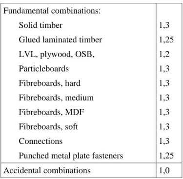
Table 2.3 Recommended partial factors γγγγM for material properties and resistances Fundamental combinations:
Solid timber 1,3
Glued laminated timber 1,25
LVL, plywood, OSB, 1,2 Particleboards 1,3 Fibreboards, hard 1,3 Fibreboards, medium 1,3 Fibreboards, MDF 1,3 Fibreboards, soft 1,3 Connections 1,3
Punched metal plate fasteners 1,25
Accidental combinations 1,0
mean d M E E
γ
= (2.15) mean d M G Gγ
= (2.16) where:Emean is the mean value of modulus of elasticity;
Gmean is the mean value of shear modulus.
2.3.2 Design value of geometrical data
Geometrical data for cross-sections and systems may be taken as nominal values from product standards hEN or drawings for the execution.
Design values of geometrical imperfections specified in this handbook comprise the effects of − geometrical imperfections of members;
− the effects of structural imperfections from fabrication and erection; − inhomogeneity of materials (e.g. due to knots).
2.3.3 Design resistances
The design value Rd of a resistance (load-carrying capacity) shall be calculated as:
k d mod M R R k
γ
= (2.17) where:Rk is the characteristic value of load-carrying capacity;
γM is the partial factor for a material property,
kmod is a modification factor taking into account the effect of the duration of load and
moisture content.
NOTE 1: Values of kmod are given in Chapter 3.
3 Design values of material properties
Eurocode 5 in common with the other Eurocodes provides no data on strength and stiffness properties for structural materials. It merely states the rules appropriate to the determination of these values to achieve compatibility with the safety format and the design rules of EC5.
3.1 Introduction
Strength and stiffness parameters
Strength and stiffness parameters shall be determined on the basis of tests for the types of action effects to which the material will be subjected in the structure, or on the basis of comparisons with similar timber species and grades or wood-based materials, or on well-established relations between the different properties.
Stress-strain relations
Since the characteristic values are determined on the assumption of a linear relation between stress and strain until failure, the strength verification of individual members shall also be based on such a linear relation.
For members or parts of members subjected to compression, a non-linear relationship (elastic-plastic) may be used.
Strength modification factors for service classes and load-duration classes The values of the modification factor kmod given in Table 3.1 should be used.
If a load combination consists of actions belonging to different load-duration classes a value of kmod should be chosen which corresponds to the action with the shortest duration, e.g. for a
combination of dead load and a short-term load, a value of kmod corresponding to the
short-term load should be used.
Table 3.1 Values of kmod
Load-duration class Material Standard Service
class Permanent action Long term action Medium term action Short term action Instanta- neous action 1 0,60 0,70 0,80 0,90 1,10 2 0,60 0,70 0,80 0,90 1,10 Solid timber EN 14081-1 3 0,50 0,55 0,65 0,70 0,90 1 0,60 0,70 0,80 0,90 1,10 2 0,60 0,70 0,80 0,90 1,10 Glued laminated timber EN 14080 3 0,50 0,55 0,65 0,70 0,90 1 0,60 0,70 0,80 0,90 1,10 2 0,60 0,70 0,80 0,90 1,10 LVL EN 14374, EN 14279 3 0,50 0,55 0,65 0,70 0,90 EN 636
Part 1, Part 2, Part 3 1 0,60 0,70 0,80 0,90 1,10
Part 2, Part 3 2 0,60 0,70 0,80 0,90 1,10
Plywood
EN 300 OSB/2 1 0,30 0,45 0,65 0,85 1,10 OSB/3, OSB/4 1 0,40 0,50 0,70 0,90 1,10 OSB OSB/3, OSB/4 2 0,30 0,40 0,55 0,70 0,90 EN 312 Part 4, Part 5 1 0,30 0,45 0,65 0,85 1,10 Particle-board Part 5 2 0,20 0,30 0,45 0,60 0,80 Part 6, Part 7 1 0,40 0,50 0,70 0,90 1,10 Part 7 2 0,30 0,40 0,55 0,70 0,90 EN 622-2 HB.LA, HB.HLA 1 or 2 1 0,30 0,45 0,65 0,85 1,10 Fibreboard, hard HB.HLA1 or 2 2 0,20 0,30 0,45 0,60 0,80 EN 622-3 MBH.LA1 or 2 MBH.HLS1 or 2 1 1 0,20 0,20 0,40 0,40 0,60 0,60 0,80 0,80 1,10 1,10 Fibreboard, medium MBH.HLS1 or 2 2 – – – 0,45 0,80 EN 622-5 MDF.LA, MDF.HLS 1 0,20 0,40 0,60 0,80 1,10 Fibreboard, MDF MDF.HLS 2 – – – 0,45 0,80
Deformation modification factors for service classes
The values of the deformation factors kdef given in Table 3.2 should be used.
3.2 Solid timber
Timber members shall comply with EN 14081-1. Timber members with round cross-section shall comply with EN 14544.
NOTE: Values of strength and stiffness properties (see Table 3.4) are given for structural timber allocated to strength classes in EN 338.
The establishment of strength classes and related strength and stiffness profiles is possible because, independently, nearly all softwoods and hardwoods commercially available exhibit a similar relationship between strength and stiffness properties.
Experimental data shows that all important characteristic strength and stiffness properties can be calculated from either bending strength, modulus of elasticity (E) or density. However, further research is required to establish the effect of timber quality on these relationships and to decide whether accuracy could be improved by modifying these retationships for different strength classes.
Deciduous species (hardwoods) have a different anatomical structure from coniferous species (softwoods). They generally have higher densities but not correspondingly higher strength and stiffness properties. This is why EN 338 provides separate strength classes for coniferous and deciduous species. Poplar, increasingly used for structural purposes, shows a density/strength relationship closer to that of coniferous species and was therefore assigned to coniferous strength classes.
Due to the relationships between strength, stiffness and density a species /source/ grade combination can be assigned to a specific strength class based on the characteristic values of bending strength, modulus of elasticity and density.
According to EN 338 a timber population can thus be assigned to a strength class provided - the timber has been visually or machine strength graded according to the specifications of
EN 518 or EN 519;
- the characteristic strength, stiffness and density values have been determined according to EN 384 “Determination of characteristic values of mechanical properties and density”; - the characteristic values of bending strength, modulus of elasticity and density of the
population are equal to or greater than the corresponding values of the related strength class. The effect of member size on strength may be taken into account.
Table 3.2 Values of kdef for timber and wood-based materials
Service class Material Standard 1 2 3 Solid timber EN 14081-1 0,60 0,80 2,00 Glued Laminated timber EN 14080 0,60 0,80 2,00 LVL EN 14374, EN 14279 0,60 0,80 2,00 EN 636 Part 1 0,80 – – Part 2 0,80 1,00 – Plywood Part 3 0,80 1,00 2,50 EN 300 OSB/2 2,25 – – OSB OSB/3, OSB/4 1,50 2,25 – EN 312 Part 4 2,25 – – Part 5 2,25 3,00 – Part 6 1,50 – – Particleboard Part 7 1,50 2,25 – EN 622-2 HB.LA 2,25 – – Fibreboard, hard HB.HLA1, HB.HLA2 2,25 3,00 – EN 622-3 MBH.LA1, MBH.LA2 3,00 – – Fibreboard, medium MBH.HLS1, MBH.HLS2 3,00 4,00 – EN 622-5 MDF.LA 2,25 – – Fibreboard, MDF MDF.HLS 2,25 3,00 –
For rectangular solid timber with a characteristic timber density
ρ
k≤ 700 kg/m3, the referencedepth in bending or width (maximum cross-sectional dimension) in tension is 150 mm. For depths in bending or widths in tension of solid timber less than 150 mm the characteristic values for fm,k and ft,0,k may be increased by the factor kh, given by:
0,2 h 150 min 1, 3 h k = (3.1)
where h is the depth for bending members or width for tension members, in mm.
For timber which is installed at or near its fibre saturation point, and which is likely to dry out under load, the values of kdef, given in Table 3.2, should be increased by 1,0.
Finger joints shall comply with EN 385.
3.3 Glued laminated timber
Glued laminated timber members shall comply with EN 14080.
NOTE: Values of strength and stiffness properties are given for glued laminated timber allocated to strength classes in EN 1194.
Formulae for calculating the mechanical properties of glulam from the lamination properties are given in Table 3.3.
The basic requirements for the laminations which are used in the formulae of Table 3.3 are the tension characteristic strength and the mean modulus of elasticity. The density of the laminations is an indicative property. These properties shall be either the tabulated values given in EN 338 or derived according to the principles given in EN 1194.
The requirements for glue line integrity are based on the testing of the glue line in a full cross-sectional specimen, cut from a manufactured member. Depending on the service class, delamination tests (according to EN 391 “Glued laminated timber - delamination test of glue lines”) or block shear tests (according to EN 392 “Glued laminated timber - glue line shear test”) must be performed.
Table 3.3 Mechanical properties of glued laminated timber (in N/mm2)
Property Bending fm g k, , = +7 1,15 ft,0, ,l k Tension ft,0, ,g k ,90, , t g k f ,0, , 5 0,8 ft l k = + ,0, , 0, 2 0, 015 ft l k = + Compresion fc,0, ,g k ,90, , c g k f 0,45 ,0, , 7, 2 ft l k = 0,5 ,0, , 0, 7 ft l k = Shear fv g k, , 0.8 ,0, , 0, 32 ft l k =
Modulus of elasticity E0, ,g mean 0, ,05g E 90, ,g mean E 0, , 1, 05E l mean = 0, , 0,85E l mean = 0, , 0, 035E l mean =
Density ρg k, =1,10ρl k,
NOTE: For combined glued laminated timber the formulae apply to the properties of the individual parts of the cross-section. It is assumed that zones of different lamination grades amount to at least 1/6 of the beam depth or two laminations, whichever is the greater.
The effect of member size on strength may be taken into account.
For rectangular glued laminated timber, the reference depth in bending or width in tension is 600 mm. For depths in bending or widths in tension of glued laminated timber less than 600 mm the characteristic values for fm,k and ft,0,k may be increased by the factor kh ,given by
0,1 h 600 min 1,1 h k = (3.2)
where h is the depth for bending members or width for tensile members, in mm.
Large finger joints complying with the requirements of ENV 387 shall not be used for products to be installed in service class 3, where the direction of grain changes at the joint. The effect of member size on the tensile strength perpendicular to the grain shall be taken into account.
3.4 Laminated veneer lumber (LVL)
LVL structural members shall comply with EN 14374.
For rectangular LVL with the grain of all veneers running essentially in one direction, the effect of member size on bending and tensile strength shall be taken into account.
The reference depth in bending is 300 mm. For depths in bending not equal to 300 mm the characteristic value for fm,k should be multiplied by the factor kh ,given by
h 300 min 1, 2 s h k = (3.3) where:
h is the depth of the member, in mm; s is the size effect exponent, see below.
The reference length in tension is 3000 mm. For lengths in tension not equal to 3000 mm the characteristic value for ft,0,k should be multiplied by the factor kℓ given by
/ 2 3000 min 1,1 s k = l l (3.4)
where ℓis the length, in mm.
The size effect exponent s for LVL shall be taken as declared in accordance with EN 14374. Large finger joints complying with the requirements of ENV 387 shall not be used for products to be installed in service class 3, where the direction of grain changes at the joint. For LVL with the grain of all veneers running essentially in one direction, the effect of member size on the tensile strength perpendicular to the grain shall be taken into account.
3.5 Wood-based panels
Wood-based panels shall comply with EN 13986 and LVL used as panels shall comply with EN 14279.
The use of softboards according to EN 622-4 should be restricted to wind bracing and should be designed by testing.
3.6 Adhesives
Adhesives for structural purposes shall produce joints of such strength and durability that the integrity of the bond is maintained in the assigned service class throughout the expected life of the structure.
Adhesives which comply with Type I specification as defined in EN 301 may be used in all service classes.
Adhesives which comply with Type II specification as defined in EN 301 should only be used in service classes 1 or 2 and not under prolonged exposure to temperatures in excess of 50 °C.
3.7 Metal fasteners
Metal fasteners shall comply with EN 14592 and metal connectors shall comply with EN 14545.
Table 3.4 Strength classes and characteristic values according to EN 338
Coniferous species and Poplar Deciduous species
C14 C16 C18 C20 C22 C24 C27 C30 C35 C40 C45 C50 D30 D35 D40 D50 D60 D70
Strength properties in N/mm2
Bending fm,k 14 16 18 20 22 24 27 30 35 40 45 50 30 35 40 50 60 70 Tension parallel to grain ft,0,k 8 10 11 12 13 14 16 18 21 24 27 30 18 21 24 30 36 42 Tension perpendicular to grain ft,90,k 0,4 0,5 0,5 0,5 0,5 0,5 0,6 0,6 0,6 0,6 0,6 0,6 0,6 0,6 0,6 0,6 0,6 0,6 Compression parallel to grain fc,0,k 16 17 18 19 20 21 22 23 25 26 27 29 23 25 26 29 32 34 Compression perpendicular to
grain
fc,90,k 2,0 2,2 2,2 2,3 2,4 2,5 2,6 2,7 2,8 2,9 3,1 3,2 8,0 8,4 8,8 9,7 10,5 13,5 Shear fv,k 1,7 1,8 2,0 2,2 2,4 2,5 2,8 3,0 3,4 3,8 3,8 3,8 3,0 3,4 3,8 4,6 5,3 6,0 Stiffness properties in kN/mm2
Mean value of modulus of elasticity parallel to grain
E0,mean 7 8 9 9,5 10 11 11,5 12 13 14 15 16 10 10 11 14 17 20 5% value of modulus of
elasticity parallel to grain
E0,05 4,7 5,4 6,0 6,4 6,7 7,4 7,7 8,0 8,7 9,4 10,0 10,7 8,0 8,7 9,4 11,8 14,3 16,8 Mean value of modulus of
elasticity pependicular to grain
E90,mean 0,23 0,27 0,30 0,32 0,33 0,37 0,38 0,40 0,43 0,47 0,50 0,53 0,64 0,69 0,75 0,93 1,13 1,33
Mean value of shear modulus Gmean 0,44 0,5 0,56 0,59 0,63 0,69 0,72 0,75 0,81 0,88 0,94 1,00 0,60 0,65 0,70 0,88 1,06 1,25 Density in kg/m3
Density ρk 290 310 320 330 340 350 370 380 400 420 440 460 530 560 590 650 700 900 Mean value of density ρmean 350 370 380 390 410 420 450 460 480 500 520 550 640 670 700 780 840 1080
4 Wood adhesives
At present there is one established EN-standard for classification of structural wood adhesives, namely EN 301, “Adhesives, phenolic and aminoplastic, for load bearing timber structures: Classification and performance requirements”. The corresponding test standard is EN 302, “Adhesives for load-bearing timber structures - Test methods. The standards apply to phenolic and aminoplastic adhesives only. These adhesives are classified as:
- type I-adhesives, which will stand full outdoor exposure, and temperatures above 50 °C; - type II-adhesives, which may be used in heated and ventilated buildings, and exterior
protected from the weather. They will stand short exposure to the weather, but not prolonged exposure to weather or to temperatures above 50 °C.
According to EC5 only adhesives complying with EN 301 may be approved at the moment. Current types of structural wood adhesives are listed below.
Resorcinol formaldehyde (RF) and Phenol-resorcinol formaldehyde (PRF) adhesives RF’s and PRF’s are type I adhesives according to EN 301. They are used in laminated beams, fingerjointing of structural members, I-beams, box beams etc., both indoors and outdoors. Phenol-formaldehyde adhesives (PF), hot-setting
Hot-setting PF's cannot be classified according to EN 301. Phenol-formaldehyde adhesives (PF), cold-setting
Cold-setting PF's are classified according to EN 301, but the current types are likely to be eliminated by the “acid damage test” given in EN 302-3.
Urea-formaldehyde adhesives (UF)
Only special cold-setting UF’s are suitable for structural purposes. In a fire they will tend to delaminate. UF’s for structural purposes are classified according to EN 301 as type II-adhesives.
Melamine-urea formaldehyde adhesives (MUF)
The cold set ones are classified according to EN 301. They are, however, less resistant than the resorcinols, and not suitable for marine purposes. However, MUF’s are often preferred for economic reasons, and because of their lighter colour.
Casein adhesives
Caseins are probably the oldest type of structural adhesive and have been used for industrial glulam production since before 1920. Caseins do not meet the requirements of EN 301.
Epoxy adhesives
Epoxy adhesives have very good gapfilling properties. Epoxies have very good strength and durability properties, and the weather resistance for the best ones lies between MUF’s and PRF’s.
Two-part polyurethanes
These adhesives have good strength and durability, but experience seems to indicate that they are not weather-resistant, at least not all of them.
5 Durability
Timber is susceptible to biological attack whereas metal components may corrode.
Under ideal conditions timber structures can be in use for centuries without significant biological deterioration. However, if conditions are not ideal, many widely used wood species need a preservative treatment to be protected from the biological agencies responsible for timber degradation, mainly fungi and insects.
5.1 Resistance to biological organisms and corrosion
Timber and wood-based materials shall either have adequate natural durability in accordance with EN 350-2 for the particular hazard class (defined in EN 335-1, EN 335-2 and EN 335-3), or be given a preservative treatment selected in accordance with EN 351-1 and EN 460. NOTE 1: Preservative treatment may affect the strength and stiffness properties.
NOTE 2: Rules for specification of preservation treatments are given in EN 350-2 and EN 335.
Metal fasteners and other structural connections shall, where necessary, either be inherently corrosion-resistant or be protected against corrosion.
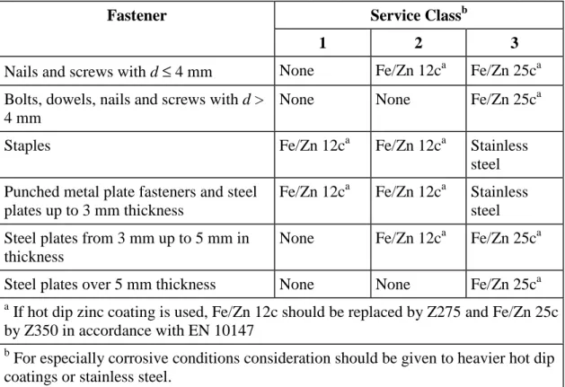
Examples of minimum corrosion protection or material specifications for different service classes are given in Table 5.1.
Table 5.1 Examples of minimum specifications for material protection against corrosion for fasteners (related to ISO 2081)
Service Classb Fastener
1 2 3
Nails and screws with d ≤ 4 mm None Fe/Zn 12ca Fe/Zn 25ca Bolts, dowels, nails and screws with d >
4 mm
None None Fe/Zn 25ca
Staples Fe/Zn 12ca Fe/Zn 12ca Stainless
steel Punched metal plate fasteners and steel
plates up to 3 mm thickness
Fe/Zn 12ca Fe/Zn 12ca Stainless steel Steel plates from 3 mm up to 5 mm in
thickness
None Fe/Zn 12ca Fe/Zn 25ca
Steel plates over 5 mm thickness None None Fe/Zn 25ca
a
If hot dip zinc coating is used, Fe/Zn 12c should be replaced by Z275 and Fe/Zn 25c by Z350 in accordance with EN 10147
b
For especially corrosive conditions consideration should be given to heavier hot dip coatings or stainless steel.
5.2 Biological attack
The two main biological agencies responsible for timber degradation are fungi and insects although in specific situations, timber can also be attacked by marine borers.
Fungal attack
This occurs in timber which has a high moisture content, generally between 20 % and 30 %. Insect attack
Insect attack is encouraged by warm conditions which favour their development and reproduction.
5.3 Classification of hazard conditions
The levels of exposure to moisture are defined differently in EC5 and EN 335-I “Durability of wood and wood-based products - Definition of hazard (use) classes of biological attack - Part 1: General”. EC5 provides for three service classes relating to the variation of timber performance with moisture content, see Chapter 2.
In EN 335-1, five hazard (use) classes are defined with respect to the risk of biological attacks:
Hazard (use) class 1, situation in which timber or wood-based product is under cover, fully protected from the weather and not exposed to wetting;
Hazard (use) class 2, situation in which timber or wood-based product is under cover and fully protected from the weather but where high environmental humidity can lead to occasional but not persistent wetting;
Hazard (use) class 3, situation in which timber or wood-based product is not covered and not in contact with the ground. It is either continually exposed to the weather or is protected from the weather but subject to frequent wetting;
Hazard (use) class 4, situation in which timber or wood-based product is in contact with the ground or fresh water and thus is permanently exposed to wetting;
Hazard (use) class 5, situation in which timber or wood-based product is permanently exposed to salt water.
5.4 Prevention of fungal attack
It is possible to reduce the risk through careful construction details, especially to reduce timber moisture content.
5.5 Prevention of insect attack
Initially, the natural durability of the selected timber species should be established with respect to the particular insect species to which it may be exposed. It is also necessary to establish whether the particular insect is present in the region in which the timber to be used.
6 Ultimate limit states
Timber structures are generally analysed using elastic structural analysis techniques the world over. This is quite appropriate for the serviceability limit state (which is fairly representative of the performance of the structure from year to year). Even the ultimate limit state (which models the failure of structural element under an extreme loading condition) can be reasonably modelled using an elastic analysis.
6.1 Design of cross-sections subjected to stress in one principal direction
This section deals with the design of simple members in a single action.
6.1.1 Assumptions
Section 6.1 applies to straight solid timber, glued laminated timber or wood-based structural products of constant cross-section, whose grain runs essentially parallel to the length of the member. The member is assumed to be subjected to stresses in the direction of only one of its principal axes (see Figure 6.1).
Key:
(1) direction of grain
Figure 6.1 Member Axes 6.1.2 Tension parallel to the grain
Tension members generally have a uniform tension field throughout the length of the member, and the entire cross section, which means that any corner at any point on the member has the potential to be a critical location. However a bending member under uniformly distributed loading will have a bending moment diagram that varies from zero at each end to the maximum at the centre. The critical locations for tension are near to the centre, and only one half of the beam cross section will have tension, so the volume of the member that is critical for flaws is much less than that for tension members.
The inhomogeneities and other deviations from an ideal orthotropic material, which are typical for structural timber, are often called defects. As just mentioned, these defects will cause a fairly large strength reduction in tension parallel to the grain. For softwood (spruce, fir) typical average value are in the range of ft,0 = 10 to 35 N/mm
2
.
In EC5 the characteristic strength values of solid timber are related to a width in tension parallel to the grain of 150 mm. For widths in tension of solid timber less than I50 mm the characteristic values may be increased by a factor k . h
For glulam the reference width is 600 mm and, analogously, for widths smaller than 600 mm a factor k should be applied. h
For long boards under uniaxial tension due consideration should be taken both of the size effect (length effect) and of the lengthwise variation of the tensile strength.
The following expression shall be satisfied: f
σt,0,d ≤ t,0,d (6.1)
where
σ
t ,0,d is the design tensile stress along the grain;ft,0,d is the design tensile strength along the grain.
6.1.3 Tension perpendicular to the grain
The lowest strength for timber is in tension perpendicular to the grain.
In timber members tensile stresses perpendicular to the grain should be avoided or kept as low as possible.
The effect of member size shall be taken into account.
6.1.4 Compression parallel to the grain
At the ultimate limit state, the compression member will have achieved its compressive capacity whether limited by material crushing (see Figure 6.2) or buckling. In contrast to the brittle, explosive failure of tension members, the compression failure is quiet and gradual. Buckling is quite silent as it is not associated with material failure at all, and crushing is accompanied by a “crunching or crackling” sound. However, in spite of the silence of failure, any structural failure can lead to loss or at least partial loss of the structural system and place a risk on human life. Both modes of failure are just as serious as the more dramatic tensile and bending failures.
Figure 6.2 Failure mechanisms in compression
The strength in compression parallel to the grain will be somewhat reduced by the growth defects to fc,0 = 25 to 40 N/mm
2
. The reduction in strength depends on the testing method. If the specimen is compressed between two stiff end plates, which are restrained from rotation, a local failure of some fibres will lead to stress redistribution over the rest of the cross section. This will result in a higher average stress than if the specimen had been loaded via a hinged endplate.
The following expression shall be satisfied: c,0,d fc,0,d
σ
≤ (6.2)where:
σ
c,0,d is the design compressive stress along the grain;fc,0,d is the design compressive strength along the grain.
NOTE: Rules for the instability of members are given in 6.3.
6.1.5 Compression perpendicular to the grain
Bearing capacity either over a support or under a load plate is a function of the crushing strength of the wood fibre. Where the bearing capacity is exceeded, local crushing occurs. This type of failure is quite ductile, but in some cases, fibre damage in the region of a support may cause flexural failure in that location.
The bearing capacity is a complex function of the bearing area. Where the bearing does not completely cover the area of timber, testing has shown a considerable increase in bearing capacity.
This is known as an “edge effect”. Figure 6.3 shows bearing failure under heavily loaded beams. The influence of growth defects on the strength perpendicular to the grain is small.
Figure 6.3 Bearing effects at supports and points of concentrated load application
The following expression shall be satisfied: c,90,d kc,90fc,90,d
σ
≤ (6.3)where:
σ
c,90,d is the design compressive stress in the contact area perpendicular to the grain;fc,90,d is the design compressive strength perpendicular to the grain;
kc,90 is a factor taking into account the load configuration, possibility of splitting and
The value of kc,90 should be taken as 1,0, unless the member arrangements in the following
paragraphs apply. In these cases the higher value of kc,90 specified may be taken, up to a
limiting value of kc,90 = 4,0.
NOTE: When a higher value of kc,90 is used, and contact extends over the full member width
b, the resulting compressive deformation at the ultimate limit state will be approximately 10 % of the member depth.
For a beam member resting on supports (see Figure 6.4), the factor kc,90 should be calculated
from the following expressions:
− When the distance from the edge of a support to the end of a beam a, ≤ h/3:
c,90 2, 38 1 250 12 h k = − + l l (6.4) − At internal supports: c,90 2, 38 1 250 6 h k = − + l l (6.5) where:
l is the contact length in mm;
h is member depth in mm.
Figure 6.4 Beam on supports
For a member with a depth h ≤ 2,5b where a concentrated force with contact over the full width b of the member is applied to one face directly over a continuous or discrete support on the opposite face, see Figure 6.5, the factor kc,90 is given by:
0,5 ef c,90 2, 38 250 k = − l l l (6.6) where:
lef is the effective length of distribution, in mm; l is the contact length, see Figure 6.5, in mm.
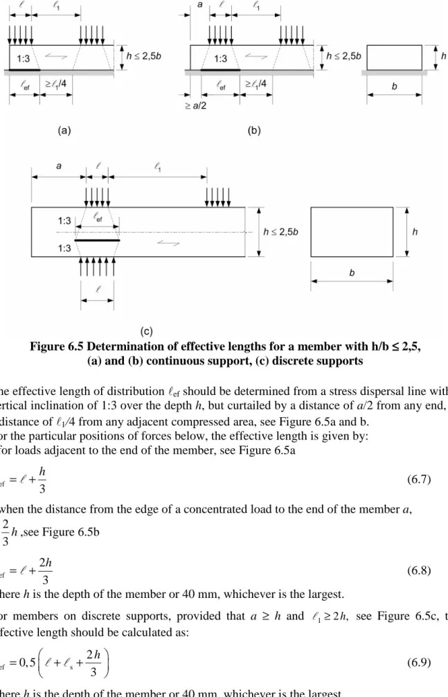
Figure 6.5 Determination of effective lengths for a member with h/b ≤≤≤≤ 2,5, (a) and (b) continuous support, (c) discrete supports
The effective length of distribution lef should be determined from a stress dispersal line with a
vertical inclination of 1:3 over the depth h, but curtailed by a distance of a/2 from any end, or a distance of l1/4 from any adjacent compressed area, see Figure 6.5a and b.
For the particular positions of forces below, the effective length is given by: - for loads adjacent to the end of the member, see Figure 6.5a
ef
3 h = +
l l (6.7)
- when the distance from the edge of a concentrated load to the end of the member a, 2 3h ≥ ,see Figure 6.5b ef 2 3 h = + l l (6.8)
where h is the depth of the member or 40 mm, whichever is the largest.
For members on discrete supports, provided that a ≥ h and l1≥2 ,h see Figure 6.5c, the
effective length should be calculated as:
ef s 2 0, 5 3 h = + + l l l (6.9)
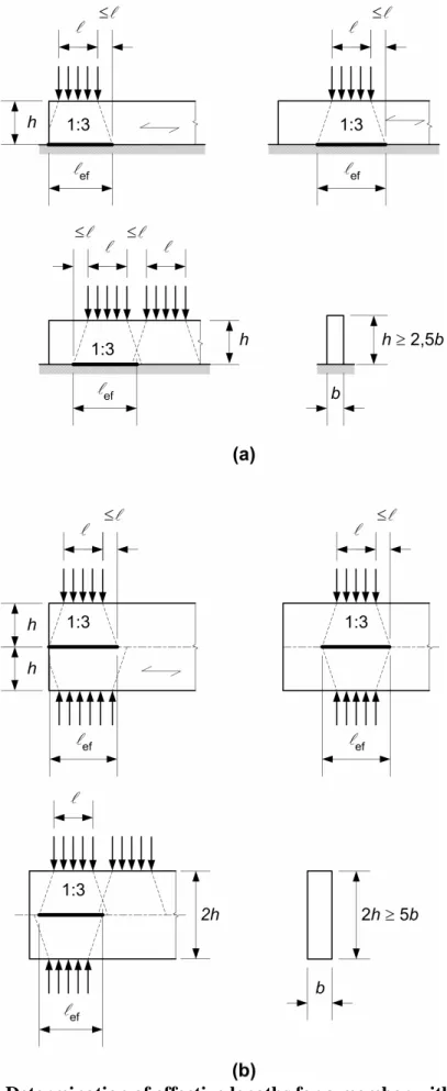
For a member with a depth h > 2,5b loaded with a concentrated compressive force on two opposite sides as shown in Figure 6.6b, or with a concentrated compressive force on one side and a continuous support on the other, see Figure 6.6a, the factor kc,90 should be calculated
according to expression (6.10), provided that the following conditions are fulfilled: − the applied compressive force occurs over the full member width b;
− the contact length l is less than the greater of h or 100 mm:
ef c,90 k =l
l (6.10)
where:
l is the contact length according to Figure 6.6;
lef is the effective length of distribution according to Figure 6.6
The effective length of distribution should not extend by more than l beyond either edge of
the contact length.
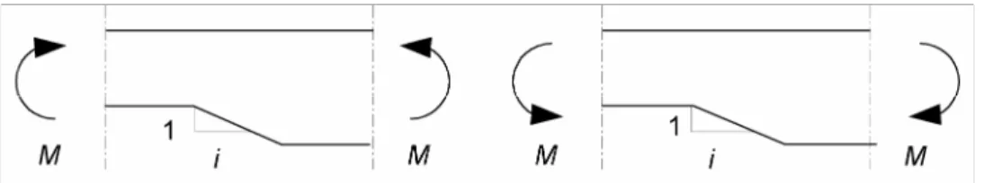
For members whose depth varies linearly over the support (e.g. bottom chords of trusses at the heel joint), the depth h should be taken as the member depth at the centreline of the support, and the effective length lef should be taken as equal to the contact length l.
Figure 6.6 Determination of effective lengths for a member with h/b > 2,5 on (a) a continuous support, (b) discrete supports
6.1.6 Bending
The most common use of a beam is to resist loads by bending about its major principal axis. However, the introduction of forces, which are not in the plane of bending, on the beam results in bi-axial bending (i.e. bending about both the major and minor principal axes). Additionally, the introduction of axial loads in tension or compression results in a further combined stress effect. For beams which are subjected to bi-axial bending, the following conditions both need to be satisfied:
The following expressions shall be satisfied: m,y,d m,z,d m m,y,d m,z,d k 1 f f
σ
+σ
≤ (6.11) m,y,d m,z,d m m,y,d m,z,d 1 k f fσ
+σ
≤ (6.12) where:σ
m,y,d andσ
m,z,d are the design bending stresses about the principal axes as shown inFigure 6.1;
fm,y,d and fm,z,d are the corresponding design bending strengths.
NOTE: The factor km makes allowance for re-distribution of stresses and the effect of
inhomogeneities of the material in a cross-section. The value of the factor km should be taken as follows:
For solid timber, glued laminated timber and LVL: for rectangular sections: km = 0,7
for other cross-sections: km = 1,0
For other wood-based structural products, for all cross-sections: km = 1,0.
A check shall also be made of the instability condition (see 6.3).
6.1.7 Shear
When bending is produced by transverse loading, shear stresses will be present according to the theory of elasticity. Shear stresses transverse to the beam axis will always be accompanied by equal shear stresses parallel to the beam axis.
For shear with a stress component parallel to the grain, see Figure 6.7(a), as well as for shear with both stress components perpendicular to the grain, see Figure 6.7(b), the following expression shall be satisfied:
d fv,d
τ
≤ (6.13)where:
τ
d is the design shear stress;NOTE: The shear strength for rolling shear is approximately equal to twice the tension strength perpendicular to grain.
Figure 6.7(a) Member with a shear stress component parallel to the grain (b) Member with both stress components perpendicular to the grain (rolling shear)
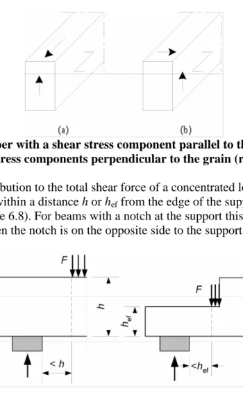
At supports, the contribution to the total shear force of a concentrated load F acting on the top side of the beam and within a distance h or hef from the edge of the support may be
disregarded (see Figure 6.8). For beams with a notch at the support this reduction in the shear force applies only when the notch is on the opposite side to the support.
Figure 6.8 Conditions at a support, for which the concentrated force F may be disregarded in the calculation of the shear force
6.1.8 Torsion
Torsional stresses are introduced when the applied load tends to twist a member. This will occur when a beam supports a load which is applied eccentric to the principal cross sectional axis. A transmission mast may be subjected to an eccentric horizontal load, resulting in a combination of shear and torsion.
The following expression shall be satisfied: tor,d kshape fv,d
τ
≤ (6.14)with
shape
1,2 for a circular cross section
1+0,15
min for a rectangular cross section
2,0 h k b = (6.15)
where:
τ
tor,d is the design torsional stress;fv,d is the design shear strength;
kshape is a factor depending on the shape of the cross-section;
h is the larger cross-sectional dimension; b is the smaller cross-sectional dimension.
6.2 Design of cross-sections subjected to combined stresses
While the design of many members is to resist a single action such as bending, tension or compression, there are many cases in which members are subjected to two of these additions simultaneously.
6.2.1 Assumptions
Section 6.2 applies to straight solid timber, glued laminated timber or wood-based structural products of constant cross-section, whose grain runs essentially parallel to the length of the member. The member is assumed to be subjected to stresses from combined actions or to stresses acting in two or three of its principal axes.
6.2.2 Compression stresses at an angle to the grain
Interaction of compressive stresses in two or more directions shall be taken into account. The compressive stresses at an angle α to the grain, (see Figure 6.9), should satisfy the following expression: c,0,d c,α,d c,0,d 2 2 c,90 c,90,d sin cos f f k f
σ
α
α
≤ + (6.16) where:σ
c,α,d is the compressive stress at an angle αto the grain;kc,90 is a factor given in 6.1.5 taking into account the effect of any of stresses
perpendicular to the grain.
Figure 6.9 Compressive stresses at an angle to the grain 6.2.3 Combined bending and axial tension
The following expressions shall be satisfied: m,y,d t,0,d m,z,d m t,0,d m,y,d m,z,d k 1 f f f
σ
σ
σ
+ + ≤ (6.17)m,y,d t,0,d m,z,d m t,0,d m,y,d m,z,d k 1 f f f
σ
σ
σ
+ + ≤ (6.18)The values of km given in 6.1.6 apply.
6.2.4 Combined bending and axial compression
The following expressions shall be satisfied: 2 m,y,d c,0,d m,z,d m c,0,d m,y,d m,z,d k 1 f f f σ σ σ + + ≤ (6.19) 2 m,y,d c,0,d m,z,d m c,0,d m,y,d m,z,d k 1 f f f σ σ σ + + ≤ (6.20)
The values of km given in 6.1.6 apply.
NOTE: To check the instability condition, a method is given in 6.3.
6.3 Stability of members
When a slender column is loaded axially, there exists a tendency for it to deflect sideways (see Figure 6.10). This type of instability is called flexural buckling. The strength of slender members depends not only on the strength of the material but also on the stiffness, in the case of timber columns mainly on the bending stiffness. Therefore, apart from the compression and bending strength, the modulus of elasticity is an important material property influencing the load-bearing capacity of slender columns. The additional bending stresses caused by lateral deflections are taken into account in a stability design.
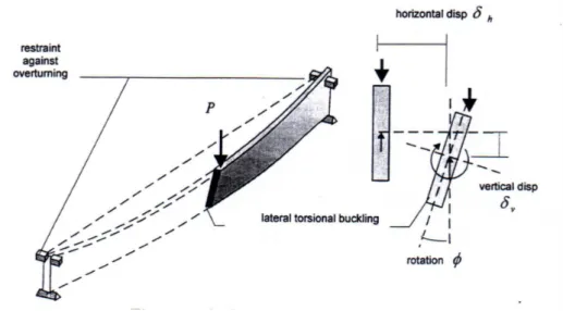
When designing beams, the prime concern is to provide adequate load carrying capacity and stiffness against bending about its major principal axis, usually in the vertical plane. This leads to a cross-sectional shape in which the stiffness in the vertical plane is often much greater than that in the horizontal plane.Whenever a slender structural element is loaded in its stiff plane (axially in the case of the column) there is a tendency for it to fail by buckling in a more flexible plane (by deflecting sideways in the case of the column). The response of a slender simply supported beam, subjected to bending moments in the vertical plane; is termed lateral-torsional buckling as it involves both lateral deflection and twisting (see Figure 6.11).
Figure 6.11 Lateral-torsional buckling of simply supported beam 6.3.1 Assumptions
The bending stresses due to initial curvature, eccentricities and induced deflection shall be taken into account, in addition to those due to any lateral load.
Column stability and lateral torsional stability shall be verified using the characteristic properties, e.g. E0,05
The stability of columns subjected to either compression or combined compression and bending should be verified in accordance with 6.3.2.
The lateral torsional stability of beams subjected to either bending or combined bending and compression should be verified in accordance with 6.3.3.
6.3.2 Columns subjected to either compression or combined compression and bending
The relative slenderness ratios should be taken as: y c,0,k rel,y 0,05 f E
λ
λ
= π (6.21) and c,0,k z rel,z 0,05 f Eλ
λ
= π (6.22) where:λy and λrel,y are slenderness ratios corresponding to bending about the y-axis (deflection in the
z-direction);
λz and λrel,z are slenderness ratios corresponding to bending about the z-axis;
E0,05 is the fifth percentile value of the modulus of elasticity parallel to the grain.
Where both λrel,z ≤0,3 and λrel,y ≤0,3 the stresses should satisfy the expressions (6.19) and
In all other cases the stresses, which will be increased due to deflection, should satisfy the following expressions: m,y,d c,0,d m,z,d m c,y c,0,d m,y,d m,z,d k 1 f f f k σ σ σ + + ≤ (6.23) m,y,d c,0,d m,z,d m c,z c,0,d m,y,d m,z,d k 1 f f f k σ σ σ + + ≤ (6.24)
where the symbols are defined as follows:
c,y 2 2 y y rel,y 1 - k k k
λ
= + (6.25) c,z 2 2 z z rel,z 1 - k k kλ
= + (6.26)(
)
(
2)
y 0, 5 1 c rel,y - 0, 3 rel,y k = +β λ
+λ
(6.27)(
)
(
2)
z 0, 5 1 c rel,z - 0, 3 rel,z k = +β λ
+λ
(6.28) where:β
c is a factor for members within the straightness limits:c
0,2 for solid timber
0,1 for glued laminated timber and LVL
β
= (6.29)
km as given in 6.1.6.
6.3.3 Beams subjected to either bending or combined bending and compression
Lateral torsional stability shall be verified both in the case where only a moment My exists
about the strong axis y and where a combination of moment My and compressive force Nc
exists.
The relative slenderness for bending should be taken as: m,k
rel,m
m,crit f
λ
=σ
(6.30)where σm,crit is the critical bending stress calculated according to the classical theory of
stability, using 5-percentile stiffness values. The critical bending stress should be taken as:
0,05 z 0,05 tor y,crit m,crit y ef y E I G I M W W
π
σ
= = l (6.31) where:G0,05 is the fifth percentile value of shear modulus parallel to grain;
Iz is the second moment of area about the weak axis z.
Itor is the torsional moment of inertia;
lef is the effective length of the beam, depending on the support conditions and the load
configuration, acccording to Table 6.1;
Wy is the section modulus about the strong axis y.
For softwood with solid rectangular cross-section, σm,crit should be taken as:
2 m,crit 0,05 ef 0, 78b E h
σ
= l (6.32) where:b is the width of the beam; h is the depth of the beam.
In the case where only a moment My exists about the strong axis y, the stresses should satisfy
the following expression: m,d kcrit fm,d
σ
≤ (6.33)where:
σm,d is the design bending stress; fm,d is the design bending strength;
kcrit is a factor which takes into account the reduced bending strength due to lateral
buckling.
Table 6.1 Effective length as a ratio of the span
Beam type Loading type llllef/lllla
Simply supported
Constant moment
Uniformly distributed load
Concentrated force at the middle of the span
1,0 0,9 0,8 Cantilever Uniformly distributed load
Concentrated force at the free end
0,5 0,8
a
The ratio between the effective length lef and the span lis valid for a beam with torsionally restrained supports and loaded at the centre of gravity. If the load is applied at the compression edge of the beam, lef should be increased by 2h and may be decreased by
0,5h for a load at the tension edge of the beam.
For beams with an initial lateral deviation from straightness within the limits kcrit may be
rel,m
crit rel,m rel,m
rel,m 2 rel,m 1 for 0, 75 1, 56 - 0, 75 for 0, 75 1, 4 1 for 1, 4 k
λ
λ
λ
λ
λ
≤ = < ≤ < (6.34)The factor kcrit may be taken as 1,0 for a beam where lateral displacement of its compressive
edge is prevented throughout its length and where torsional rotation is prevented at its supports.
In the case where a combination of moment My about the strong axis y and compressive force
Nc exists, the stresses should satisfy the following expression:
2 m,d c,d crit m,d c,z c,0,d 1 k f k f
σ
σ
+ ≤ (6.35) where:σm,d is the design bending stress; σc,d is the design compressive stress;
fc,0,d is the design compressive strength parallel to grain;
kc,z is given by expression (6.26).
6.4 Design of cross-sections in members with varying cross-section or curved shape
Due to the range of sizes, lengths and shapes available, glulam is frequently used for different beams. It is rare for sawn timber to be used as tapered or curved beams because of the
difficulty obtaining large sized cross section material and difficulties in bending it about its major axis to give a curved longitudinal profile.
6.4.1 Assumptions
The effects of combined axial force and bending moment shall be taken into account. The relevant parts of 6.2 and 6.3 should be verified.
The stress at a cross-section from an axial force may be calculated from
N N
A
σ = (6.36)
where:
σN is the axial stress;
N is the axial force;
6.4.2 Single tapered beams
The influence of the taper on the bending stresses parallel to the surface shall be taken into account.
Key:
(1) cross-section
Figure 6.12 Single tapered beam
The design bending stresses, σm,α,d and σm,0,d (see Figure 6.12) may be taken as: d m, ,d m,0,d 2 6 M b h α σ =σ = (6.37)
At the outermost fibre of the tapered edge, the stresses should satisfy the following expression:
m,α,d km,α fm,d
σ ≤ (6.38)
where:
σm,α,d is the design bending stress at an angle to grain; fm,d is the design bending strength;
km,α should be calculated as:
For tensile stresses parallel to the tapered edge: m,α 2 2 m,d m,d 2 t,90,d v,d 1 1 tan tan 0, 75 k f f f
α
fα
= + + (6.39)For compressive stresses parallel to the tapered edge: m,α 2 2 m,d m,d 2 c,90,d v,d 1 1 tan tan 1, 5 k f f f
α
fα
= + + (6.40)6.4.3 Double tapered, curved and pitched cambered beams
This section applies only to glued laminated timber and LVL.
In the apex zone (see Figure 6.13), the bending stresses should satisfy the following expression:
m,d k fr m,d
σ ≤ (6.41)
where kr takes into account the strength reduction due to bending of the laminates during
production.
NOTE: In curved and and pitched cambered beams the apex zone extends over the curved part of the beam.
The apex bending stress should be calculated as follows: ap,d m,d 2 ap 6 k M b h
σ
= l (6.42) with: 2 3 ap ap ap 1 2 3 4 h h h k k k k k r r r = + + + l (6.43) 2 1 1 1, 4 tan ap 5, 4 tan ap k = +α
+α
(6.44) 2 0, 35 - 8 tan ap k = α (6.45) 2 3 0, 6 8, 3 tan ap - 7,8 tan ap k = +α
α
(6.46) 2 4 6 tan ap k =α
(6.47) in 0, 5 ap r= +r h (6.48) where:Map,d is the design moment at the apex;
hap is the depth of the beam at the apex, see Figure 6.13;
b is the width of the beam;
rin is the inner radius, see Figure 6.13;
αap is the angle of the taper in the middle of the apex zone, see Figure 6.13.
For double tapered beams kr = 1,0. For curved and pitched cambered beams kr should be taken
as: in r in in 1 for 240 0, 76 0, 001 for 240 r t k r r t t ≥ = + < (6.49) where
rin is the inner radius, see Figure 6.13;
Key:
(1) Apex Zone
NOTE: In curved and pitched cambered beams the apex zone extends over the curved parts of the beam.
Figure 6.13 Double tapered (a), curved (b) and pitched cambered (c) beams with the fibre direction parallel to the lower edge of the beam
In the apex zone the greatest tensile stress perpendicular to the grain, σt,90,d, should satisfy the
following expression: t,90,d kdis kvol ft,90,d