2001-10-16
prEN 1995-1-2
Eurocode 5 – Design of timber structures
Part 1-2: General rules – Structural fire design
Final Draft - October 2001
Stage 34
Contents
Contents 1
Foreword 3
Background of the Eurocode programme 3
Status and field of application of Eurocodes 4
National Standards implementing Eurocodes 4
Links between Eurocodes and harmonised technical specifications (ENs and ETAs) for
products 5
Additional information specific to EN 1995-1-2 5
National Annex for EN 1995-1-2 8
Section 1 General 9
1.1 Scope 9
1.2 Normative references 9
1.3 ASSUMPTIONS 10
1.4 Distinction between principles and application rules 10
1.5 Definitions 10
1.6 Symbols 11
Section 2 Basic principles and rules 14
2.1 Performance requirements 14
2.1.1 General 14
2.1.2 Nominal fire exposure 14
2.1.3 Parametric fire exposure 14
2.2 Actions 15
2.3 Design values of material properties and resistances 15
2.4 Assessment methods 16
2.4.1 General 16
2.4.2 Member analysis 17
2.4.3 Analysis of parts of the structure 18
2.4.4 Global structural analysis 19
Section 3 Material properties 20
3.1 Mechanical properties 20 3.2 Thermal properties 20 3.3 Charring 20 3.3.1 General 20 3.3.2 Unprotected surfaces 21 3.3.3 Protected surfaces 23 3.4 Adhesives 27
Section 4 Design procedures for mechanical resistance 29
4.1 General 29
4.2 Simplified rules for cross sectional resistance 29
4.2.1 General 29
4.2.2 Reduced cross section method 29
4.2.3 Reduced properties method 30
4.3 Simplified rules for analysis of structural members and components 32
4.3.1 General 32
4.3.2 Beams 32
4.3.3 Columns 32
4.3.4 Mechanically jointed members 32
4.3.5 Bracings 33
4.4 Advanced calculation methods 33
4.4.1 General 33
4.4.2 Thermal response 33
(4) The structural response model should take into account the effects of non-linear material
properties. 34
Section 5 Design procedures for wall and floor assemblies 35
5.1 General 35
5.2 Analysis of load bearing function 35
5.3 Analysis of separating function 35
5.3.1 General 35
5.3.2 Simplified method for the analysis of insulation 36
5.3.2.1 General 36
5.3.2.2 Basic insulation values, position coefficients and effect of joints 37
5.4 Advanced calculation methods 43
Section 6 Connections 44
6.1 General 44
6.2 Connections with side members of wood 44
6.2.1 Simplified rules 44
6.2.1.1 Unprotected connections 44
6.2.1.2 Protected connections 45
6.2.1.3 Additional rules for connections with internal steel plates 47
6.2.2 Reduced load method 47
6.2.2.1 Unprotected connections 47
6.2.2.2 Protected connections 49
6.3 Connections with external steel plates 49
6.3.1 Unprotected connections 49
6.3.2 Protected connections 49
6.4 Axially loaded screws 49
6.4.1 Simplified rules 49
6.4.3 Advanced method 50
Section 7 Detailing 51
7.1 Walls and floors 51
7.1.1 Dimensions and spacings 51
7.1.2 Detailing of panel connections 51
7.1.3 Insulation 52
7.2 Other elements 52
Annex A (Informative) Parametric fire exposure 54
A.1 General 54
A.2 Charring rates and charring depths 54
A.3 Mechanical resistance of members in edgewise bending 55 Annex B (informative) Thermal and mechanical material properties 57
B.1 Timber 57
B.1.1 Thermal properties 57
B.1.2 Mechanical properties 59
Annex C (Informative) Load-bearing floor joists and wall studs 61
C.1 Residual cross section 61
C.2 Reduction of strength and stiffness parameters 64
Annex D (informative) Advanced methods for glued-in screws and steel rods 67
D.1 Glued-in screws 67
D.2 Glued-in steel rods 68
Foreword
This European Standard EN 1995-1-2, Design of timber structures – General rules – Structural fire design, has been prepared on behalf of Technical Committee CEN/TC250 “ Structural Eurocodes”, the Secretariat of which is held by BSI. CEN/TC250 is responsible for all Structural Eurocodes.
The text of the draft standard was submitted to the formal vote and was approved by CEN as EN 1995-1-2 on YYYY-MM-DD.
No existing European Standard is superseded.
Background of the Eurocode programme
In 1975, the Commission of the European Community decided on an action programme in the field of construction, based on article 95 of the Treaty. The objective of the programme was the elimination of technical obstacles to trade and the harmonisation of technical specifications.
Within this action programme, the Commission took the initiative to establish a set of
harmonised technical rules for the design of construction works which, in a first stage, would serve as an alternative to the national rules in force in the Member States and, ultimately, would replace them.
For fifteen years, the Commission, with the help of a Steering Committee with Representatives of Member States, conducted the development of the Eurocodes programme, which led to the first generation of European codes in the 1980’s.
In 1989, the Commission and the Member States of the EU and EFTA decided, on the basis of an agreement1 between the Commission and CEN, to transfer the preparation and the
publication of the Eurocodes to the CEN through a series of Mandates, in order to provide them with a future status of European Standard (EN). This links de facto the Eurocodes with the provisions of all the Council’s Directives and/or Commission’s Decisions dealing with European standards (e.g. the Council Directive 89/106/EEC on construction products CPD -and Council Directives 93/37/EEC, 92/50/EEC -and 89/440/EEC on public works -and services and equivalent EFTA Directives initiated in pursuit of setting up the internal market).
The Structural Eurocode programme comprises the following standards generally consisting of a number of Parts:
EN 1990 Eurocode : Basis of Structural Design EN 1991 Eurocode 1: Actions on structures
EN 1992 Eurocode 2: Design of concrete structures EN 1993 Eurocode 3: Design of steel structures
EN 1994 Eurocode 4: Design of composite steel and concrete structures EN 1995 Eurocode 5: Design of timber structures
EN 1996 Eurocode 6: Design of masonry structures EN 1997 Eurocode 7: Geotechnical design
EN 1998 Eurocode 8: Design of structures for earthquake resistance EN 1999 Eurocode 9: Design of aluminium structures
1Agreement between the Commission of the European Communities and the European Committee for Standardisation (CEN) concerning the work on EUROCODES for the design of building and civil engineering works (BC/CEN/03/89).
Eurocode standards recognise the responsibility of regulatory authorities in each Member State and have safeguarded their right to determine values related to regulatory safety matters at national level where these continue to vary from State to State.
Status and field of application of Eurocodes
The Member States of the EU and EFTA recognise that EUROCODES serve as reference documents for the following purposes:
as a means to prove compliance of building and civil engineering works with the essential requirements of Council Directive 89/106/EEC, particularly Essential Requirement N°1 – Mechanical resistance and stability – and Essential Requirement N°2 – Safety in case of fire;
as a basis for specifying contracts for construction works and related engineering services;
as a framework for drawing up harmonised technical specifications for construction products (ENs and ETAs).
The Eurocodes, as far as they concern the construction works themselves, have a direct relationship with the Interpretative Documents2referred to in Article 12 of the CPD, although
they are of a different nature from harmonised product standards3. Therefore, technical
aspects arising from the Eurocodes work need to be adequately considered by CEN Technical Committees and/or EOTA Working Groups working on product standards with a view to achieving a full compatibility of these technical specifications with the Eurocodes. The Eurocode standards provide common structural design rules for everyday use for the design of whole structures and component products of both a traditional and an innovative nature. Unusual forms of construction or design conditions are not specifically covered and additional expert consideration will be required by the designer in such cases.
National Standards implementing Eurocodes
The National Standards implementing Eurocodes will comprise the full text of the Eurocode (including any annexes), as published by CEN, which may be preceded by a National title page and National Foreword, and may be followed by a National Annex.
The National annex may only contain information on those parameters which are left open in the Eurocode for national choice, known as Nationally Determined Parameters, to be used for the design of buildings and civil engineering works to be constructed in the country concerned, i.e.:
– values and/or classes where alternatives are given in the Eurocode, – values to be used where a symbol only is given in the Eurocode, – country specific data (geographical, climatic, etc.), e.g. snow map,
– the procedure to be used where alternative procedures are given in the Eurocode.
2
According to Art. 3.3 of the CPD, the essential requirements (ERs) shall be given concrete form in interpretative documents for the creation of the necessary links between the essential requirements and the mandates for harmonised ENs and
ETAGs/ETAs.
3According to Art. 12 of the CPD the interpretative documents shall :
a) give concrete form to the essential requirements by harmonising the terminology and the technical bases and indicating classes or levels for each requirement where necessary ;
b) indicate methods of correlating these classes or levels of requirement with the technical specifications, e.g. methods of calculation and of proof, technical rules for project design, etc. ;
c) serve as a reference for the establishment of harmonised standards and guidelines for European technical approvals. The Eurocodes, de facto, play a similar role in the field of the ER 1 and a part of ER 2.
It may also contain
– decisions on the application of informative annexes,
– references to non-contradictory complementary information to assist the user to apply the Eurocode.
Links between Eurocodes and harmonised technical specifications (ENs and ETAs) for products
There is a need for consistency between the harmonised technical specifications for construction products and the technical rules for works4. Furthermore, all the information
accompanying the CE Marking of the construction products which refer to Eurocodes shall clearly mention which Nationally Determined Parameters have been taken into account.
Additional information specific to EN 1995-1-2
EN 1995-1-2 describes the principles, requirements and rules for the structural design of buildings exposed to fire, including the following aspects.
Safety requirements
EN 199x-1-2 is intended for clients (e.g. for the formulation of their specific requirements), designers, contractors and relevant authorities.
The general objectives of fire protection are to limit risks with respect to the individual and society, neighbouring property, and where required, directly exposed property, in the case of fire.
Construction Products Directive 89/106/EEC gives the following essential requirement for the limitation of fire risks:
"The construction works must be designed and build in such a way, that in the event of an outbreak of fire
− the load bearing resistance of the construction can be assumed for a specified period of time;
− the generation and spread of fire and smoke within the works are limited;
− the spread of fire to neighbouring construction works is limited;
− the occupants can leave the works or can be rescued by other means;
− the safety of rescue teams is taken into consideration".
According to the Interpretative Document "Safety in Case of Fire5" the essential requirement
may be observed by following various possibilities for fire safety strategies prevailing in the Member States like conventional fire scenarios (nominal fires) or natural fire scenarios (parametric fires), including passive and/or active fire protection measures.
The fire parts of Structural Eurocodes deal with specific aspects of passive fire protection in terms of designing structures and parts thereof for adequate load bearing resistance and for limiting fire spread as relevant.
Required functions and levels of performance can be specified either in terms of nominal (standard) fire resistance rating, generally given in National fire regulations, or by referring to the fire safety engineering for assessing passive and active measures.
4see Art.3.3 and Art.12 of the CPD, as well as clauses 4.2, 4.3.1, 4.3.2 and 5.2 of ID 1.
Supplementary requirements concerning, for example
the possible installation and maintenance of sprinkler systems;
conditions on occupancy of building or fire compartment;
the use of approved insulation and coating materials, including their maintenance are not given in this document, because they are subject to specification by the competent authority.
Numerical values for partial factors and other reliability elements are given as recommended values that provide an acceptable level of reliability. They have been selected assuming that an appropriate level of workmanship and of quality management applies.
Design procedure
A full analytical procedure for structural fire design would take into account the behaviour of the structural system at elevated temperatures, the potential heat exposure and the
beneficial effects of active fire protection systems, together with the uncertainties associated with these three features and the importance of the structure (consequences of failure). At the present time it is possible to undertake a procedure for determining adequate performance which incorporates some, if not all, of these parameters, and to demonstrate that the structure, or its components, will give adequate performance in a real building fire. However, where the procedure is based on a nominal (standard) fire the classification system , which call for specific periods of fire resistance, takes into account (though not explicitly), the features and uncertainties described above.
Application of this Part 1-2 of EN 1995 is illustrated below. The prescriptive and
performance-based approach are identified. The prescriptive approach uses nominal fires to generate thermal actions. The performance-based approach, using fire safety engineering, refers to thermal actions based on physical and chemical parameters.
Project design
Prescriptive rules (Thermal actions given by nominal fire
curves)
Performance-based Code
(Physically based thermal actions)
Member
analysis Analysis of partof the structure
Analysis of entire structure Calculation of action effects Simplified models Advanced models Calculation of action effects Selection of actions Simplified models Advanced models Advanced models Selection of simplified or advanced fire development model Advanced models Member analysis Analysis of part of the structure Analysis of entire structure Simplified models Calculation of action effects Calculation of action effects Calculation of action effects Advanced models Advanced models
Figure – Design procedures
For design according to this part, EN 1991-1-2 is required for the determination of thermal and mechanical actions to the structure.
Design aids
It is expected, that design aids based on the calculation models given in ENV 1995-1-2, will be prepared by interested external organisations.
The main text of EN 1995-1-2 includes most of the principal concepts and rules necessary for direct application for structural fire design of timber structures.
In an annex E (informative), guidance is given to help the user selecting relevant procedures for the design of timber structures.
National Annex for EN 1995-1-2
This standard gives alternative procedures, values and recommendations for classes with notes indicating where national choices may have to be made. Therefore the National Standard implementing EN 1995-1-2 should have a National annex containing all Nationally Determined Parameters to be used for the design of buildings and civil engineering works to be constructed in the relevant country.
National choice is allowed in EN 1995-1-2 through: 2.3(1)P
2.3(2) 2.3(4) 2.4.2(3) 4.2.1(1)
Section 1 General
1.1 Scope(1)P This Part 1-2 of EN 1995 deals with the design of timber structures for the accidental situation of fire exposure and is intended to be used in conjunction with EN 1995-1-1 and EN 1991-1-2. This Part 1-2 of EN 1995 only identifies differences from, or supplements to, normal temperature design.
(2)P This Part 1-2 of EN 1995 deals only with passive methods of fire protection. Active methods are not covered.
(3)P This Part 1-2 of EN 1995 applies to building structures that are required to fulfil certain functions when exposed to fire, in terms of
– avoiding premature collapse of the structure (load-bearing function)
– limiting fire spread (flames, hot gases, excessive heat) beyond designated areas (separating function).
(4)P This Part 1-2 of EN 1995 gives principles and application rules for designing structures for specified requirements in respect of the aforementioned functions and levels of
performance.
(5)P This Part 1-2 of EN 1995 applies to structures or parts of structures that are within the scope of EN 1995-1-1 and are designed accordingly.
(6)P The methods given in this Part 1-2 of EN 1995 are applicable to all products covered by product standards made reference to in this Part.
1.2 Normative references
(1)P The following normative documents contain provisions which, through reference in this text, constitute provisions of this European Standard. For dated references, subsequent amendments to, or revisions of, any of these publications do not apply. However, parties to agreements based on this European Standard are encouraged to investigate the possibility of applying the most recent editions of the normative documents indicated below. For undated references, the latest edition of the normative document referred to applies.
EN 300 Oriented strand boards (OSB) – Definitions, classification and specifications
EN 301 Adhesives, phenolic and aminoplastic for load bearing timber structures; classification and performance requirements EN 309 Particleboards – Definition and classification
EN 313-1 Plywood – Classification and terminology Part 1: Classification
EN 316 Wood fibreboards – Definition, classification and symbols prEN 336 Structural timber – Coniferous and poplar – Sizes, permissible
deviations
EN 338 Structural Timber – Strength classes
prEN 520 Gypsum plasterboards - Specifications - Test methods EN 912 Timber fasteners – Specifications for connectors for timber EN 1194 Glued laminated timber - Strength classes and determination of
characteristic values
EN 1363-1 Fire resistance tests – General requirements
EN 1365-2 Fire resistance tests for loadbearing elements – Part 2: Floors and roofs
EN 1990 Eurocode: Basis of structural design EN 1991-1-1 Eurocode 1 Actions on structures
Part 1.1: General actions – Densities, self-weight and imposed loads
ENV 1991-1-2 Eurocode 1: Actions on structures
Part 1-2: General actions – Actions on structures exposed to fire EN 1993-1-2 Eurocode 3: Design of steel structures
Part 1-2: General – Structural fire design EN 1995-1-1 Eurocode 5: Design of timber structures
Part 1.1: General rules – General rules and rules for buildings EN 12 369–1 Wood-based panels – Characteristic values for structural design –
Part 1: OSB, particleboards and fibreboards
prENV 13381-7 Fire tests on elements of building construction – Test method for d EN 13162 Thermal insulation products for buildings – factory made mineral
wool (MW) products – Specifications M/103
prENV 13381-7 Test methods for determining the contribution to the fire resistance of structural members – Part 7: Applied protection to timber
members
prEN 13986 Wood-based panels for use in construction - Characteristics, evaluation of conformity and marking
prEN 124-aaa Timber structures – Structural laminated veneer lumber – Requirements
1.3 ASSUMPTIONS
(1) In addition to the general assumptions of EN 1990 it is assumed that any active fire protection measure taken into account in the design of the structure will be adequately maintained.
1.4 Distinction between principles and application rules
(1) The rules in EN 1990 clause 1.4 apply.
1.5 Definitions
(1)P The rules in EN 1990 clause 1.4 apply.
(2)P The following terms are used in Part 1-2 of EN 1995 with the following meanings:
1.3.1
Char-line: Border line between the char-layer and the residual cross section
1.3.2
Effective cross section: Cross section of the member in structural fire design used in the effective cross-section method. It is obtained from the residual cross section by removing parts of the cross section with assumed zero strength and stiffness
1.3.3
Failure time of protection: Duration of protection against direct fire exposure; that is the time when the fire protective cladding or other protection falls off the timber member, a
structural member initially protecting the member fails due to collapse, or the protection from other structural member is terminated due to excessive deformation
1.3.4
Fire protection material: Any material or combination of materials applied to a structural member or element for the purpose of increasing its fire resistance.
1.3.5
Normal temperature design: Ultimate limit state design for ambient temperatures according to ENV 1995-1-1
1.3.6
Protected members: Members for which measures are taken to reduce the temperature rise in the member and to prevent or reduce charring due to fire;
1.3.7
Residual cross section: Cross section of the original member reduced with the charring depth;
1.3.8
Resistance ratio in the fire situation: The ratio of the characteristic resistance of a member or a connection in the fire situation and the corresponding characteristic resistance at normal temperature.
1.6 Symbols
For the purpose of this Part 1-2 of EN 1995, the following symbols apply: Latin upper case letters
A Total area of vertical openings of fire compartment Ar Area of the residual cross
At Total area of floors, walls and ceilings that enclose the fire compartment
E20 20 % fractile of modulus of elasticity at normal temperature
E0,05 Characteristic value of modulus of elasticity (5 % fractile)
Ed Design effect of actions
Ed,fi Design modulus of elasticity in fire; design effect of actions for the fire situation
FEd,fi Design effect of actions on the connection for the fire situation
FRk Characteristic mechanic resistance of the connection at normal temperature
without the effect of load duration and moisture (kmod = 1)
FR,20 20 % fractile of a resistance
Kfi Slip modulus in the fire situation
Ku Slip modulus for the ultimata limit state at normal temperature
O Opening factor
Qk,1 Characteristic value of leading variable action 1
Gk Characteristic value of permanent action
Wef Section modulus of effective cross section
Wr Section modulus of residual cross section
Latin lower case letters
a0 Parameter
a1 Parameter
b Width
b0 Parameter
b1 Parameter
c Specific heat
d Diameter of fastener
d0 Depth of layer with assumed zero strength and stiffness
dchar,0 Charring depth for one dimensional charring
dchar,n Notional charring depth
def Effective charring depth
dg Gap depth
f20 20 % fractile strength at normal temperature
fd,fi Design strength in fire
fk Characteristic strength
fv,k Characteristic shear strength
d Depth
heq Weighted average of heights of all vertical openings
hins Insulation thickness
hp Fire protective panel thickness
k Parameter
k0 Coefficient
k2 Insulation coefficient
k3 Post-protection coefficient
kfi Coefficient
kflux Heat flux coefficient for fasteners
kh Panel thickness coefficient
kj Joint coefficient
kn Notional cross section coefficient
kmod Modification factor
kmod,fi Modification factor for fire
kmod,fi,E Modification factor for modulus of elasticity in the fire situation
kmod,fi,fm Modification factor for bending strength in the fire situation
kpos Position coefficient
kρ Density coefficient
kΘ Temperature dependent reduction factor for local strength or stiffness property lp Span of the panel
la Anchorage length of fastener
la,min Minimum anchorage length of fastener
lf Length of fastener
p Perimeter of the fire exposed residual cross section
qt,d Design fire load density related to the total area of floors, walls and ceilings
which enclose the fire compartment t Time of fire exposure
t1 Thickness of the side member
tch Time of start of charring of protected members (delay of start of charring due to
protection)
tf Failure time of protection
tfi,d Time of the fire resistance of the unprotected connection
tins Time of temperature increase on the unexposed
tins,0,i Basic insulation value of layer “i”
tj
tp,min Minimum thickness of panel
tR Time of fire resistance with respect to the load-bearing function
treq Required time of fire resistance
y Co-ordinate
Greek upper case letters
Θ Temperature
Greek lower case letters
β0 Basic charring rate for one-dimensional charring
βn Notional charring rate
βpar Charring rate during heating phaseof parametric fire curve
ηconn Conversion factor for the reduction of the load-bearing capacity in fire
ηf Conversion coefficient
γGA Partial factor for permanent actions in accidental design situations
γM Partial factor for a material property, also accounting for for model uncertainties
and dimensional variations
γM,fi Partial factor for timber in fire
γQ,1 Partial factor for variable action 1
λ Thermal conductivity
ρ Density
ρk Characteristic density
ω Moisture content
ψ1,1 Combination factor for frequent value of a variable action
ψ2,1 Combination factor for quasi-permanent value of a variable action
ψfi Combination factor for frequent values in the fire situation
6
Section 2 Basic principles and rules
2.1 Performance requirements
2.1.1 General
(1)P Where mechanical resistance in the case of fire is required, structures shall be designed and constructed in such a way that they maintain their load bearing function during the relevant fire exposure.
(2)P Where compartmentation is required, the elements forming the boundaries of the fire compartment, including joints, shall be designed and constructed in such a way, that they maintain their separating function during the relevant fire exposure, i.e.
– integrity failure does not occur; – insulation failure does not occur;.
– thermal radiation from the unexposed side is limited.
NOTE: There is no risk of fire spread due to radiation with a unexposed surface temperature below 300°C.
(3)P Deformation criteria shall be applied where the means of protection, or the design criteria for separating elements, require that the deformation of the load bearing structure is taken into account.
(4) Deformation criteria need not be applied where the efficiency of the means of protection has been verified by tests.
2.1.2 Nominal fire exposure
(1)P For standard fire exposure elements shall comply with criteria R, E and I as follows: – separating function only: integrity (criterion E) and, when requested, insulation (criterion I); – load bearing function only: mechanical resistance (criterion R);
– separating and load bearing function: criteria R, E and, when requested, I
(2) For criterion R the load bearing function should be maintained during the required time of standard fire exposure.
(3) For criterion I the average temperature rise over the whole of the non-exposed surface should be limited to 140 K, and the maximum temperature rise at any point of that surface should not exceed 180 K.
2.1.3 Parametric fire exposure
(1) The load-bearing function should be maintained during the complete endurance of the fire including the decay phase, or a specified period of time.
(2) For the verification of the separating function the following applies:
– the average temperature rise of the unexposed side of the construction should be limited to 140 K and the maximum temperature rise of the unexposed side should not exceed 180 K during the heating phase until the maximum gas temperature in the fire compartment is reached;
– the average temperature rise of the unexposed side of the construction should be limited to 180 K and the maximum temperature rise of the unexposed side should not exceed 240 K during the decay phase or for a required period of time;
assuming that the normal temperature is 20°C.
2.2 Actions
(1)P Thermal and mechanical actions shall be taken from EN 1991-1-2.
(2) For surfaces of wood, wood-based materials and gypsum plasterboard the emissivity coefficient should be taken equal to 0,8.
2.3 Design values of material properties and resistances
(1)P For verification of mechanical resistance, the design strengthand stiffness parameters shall be determined from
d,fi
f
= k
mod,fif
M,fi 20γ
(2.1) d,f i mod,fi M,fiE
= k
E
20γ
(2.2) wherefd,fi is the design strength in fire;
Ed,fi is the design stiffness parameter (modulus of elasticity or shear modulus) in fire;
f20 is the 20 % fractile of strength at normal temperature;
E20 is the 20 % fractile of modulus of elasticity at normal temperature;
kmod,fi is the modification factor for fire;
γM,fi is the partial safety factor for timber in fire.
NOTE 1: The modification factor for fire takes into account the reduction of strength and stiffness parameters at elevated temperatures. The modification factor for fire replaces the modification factor for normal temperature design kmod given in EN 1995-1-1. Values of kmod,fi are given in the
relevant clauses.
NOTE 2: The recommended partial safety factor for mechanical material properties is γM,fi = 1,0.
The choice of the value is to be made by at the national level. Information about the values to be used in the country of application may be given in a National Informative Annex to this European Standard.
(2) The design mechanical resistance of connections with fasteners in shear should be calculated as Rd,fi conn R20 M,fi
F
=
η
F
γ
(2.3) whereFRd,fi is the design mechanical resistance of connections in the fire situation at time t;
FR20 is the 20 % fractile value of the mechanical resistance of connections at normal
temperature without the effect of load duration and moisture (kmod = 1);
γM,fi is the partial safety factor for timber in fire.
Note: See (2) Note 2
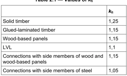
(3) The 20 % fractiles of strength and modulus of elasticity may be calculated as
f20 =k ffi k (2.4)
E
20=
k E
fi 0,05 (2.5)where kfi should be taken from table 2.1.
Table 2.1 — Values of kfi kfi Solid timber 1,25 Glued-laminated timber 1,15 Wood-based panels 1,15 LVL 1,1
Connections with side members of wood and wood-based panels
1,15 Connections with side members of steel 1,05
(4) The 20 % fractiles of the mechanical resistance of connections should be calculated as
F
R,20=
k F
fi R,k (2.6)where
kfi is given in table 2.1.
Fr,k is the characteristic mechanic resistance of connections at normal temperature without
the effect of load duration and moisture (kmod = 1).
(5) For design values of temperature dependent thermal properties see 3.2.
2.4 Assessment methods
2.4.1 General
(1)P The model of the structural system adopted for design shall reflect the performance of the structure in the fire situation.
(2)P It shall be verified for the required duration of fire exposure t:
Ed,fi≤ Rd,t,fi (2.7)
where
Efi,d is the design effect of actions for the fire situation, determined in accordance with
EN 1991-1-2, including effects of thermal expansions and deformations Rfi,t,d is the corresponding design resistance in the fire situation.
– (3) The analysis for the fire situation should be carried out according to EN 1990 5.1.4(2). NOTE: A member analysis is performed as an equivalent to standard fire testing of elements or members.
(4)P The effect of thermal expansions of materials other than timber shall be taken into account.
(5) Where application rules given in this Part 1-2 of EN 1995 are valid only for the standard temperature-time curve, this is identified in the relevant clauses.
(5) As an alternative to design by calculation, fire design may be based on the results of fire tests, or on fire tests in combination with calculations, see EN 1990 clause 5.2.
2.4.2 Member analysis
(1) The effect of actions should be determined for time t = 0 using combination factors ψ1,1 or
ψ2,1 according to EN 1991-1-2 clause 4.3.1.
(2) As a simplification to (1), the effect of actions Ed,fimay be obtained from the analysis for
normal temperature as
E
d,fi=
η
fiE
d (2.8)where
Ed is the design effect for normal temperature design for the fundamental
combination of actions, see EN 1990;
ηfi is the reduction factor for the design load in the fire situation.
(3) The reduction factor ηfi for load combination (6.10) in EN 1990 should be taken as
η
ψ
γ
γ
fi k fi k,1 G k k,1=
+
+
G
Q
G
Q,1Q
(2.9)or, for load combinations (6.10a) and (6.10b) in EN 1990, as the smallest value given by the following two expressions
η
ψ
γ
γ
fi k fi k,1 G k k,1=
+
+
G
Q
G
Q,1Q
(2.9a)η
ψ
ξ γ
γ
fi k fi k,1 G k k,1=
+
+
G
Q
G
Q,1Q
(2.9b) whereQk,1 is the characteristic value of the principle variable action;
Gk is the characteristic value of a permanent action;
γG is the partial factor for permanent actions;
ψfi is the combination factor for frequent values of variable actions, see EN 1991-1-2
ξ is a reduction factor for unfavourable permanent actions G.
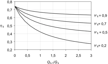
NOTE 1: An example of the variation of the reduction factor ηfi versus the load ratio Qk,1/Gk for
different values of the combination factor ψfiaccording to expression (2.9) is shown in figure 2.1 with
the following assumptions: γGA = 1,0, γG = 1,35 and γQ = 1,5. Partial factors are specified in the
relevant National annexes of EN 1990. Expressions (2.9a) and (2.9b) give slightly higher values.
0,2 0,3 0,4 0,5 0,6 0,7 0,8 0 0,5 1 1,5 2 2,5 3 Qk,1/Gk ηfi ψfi = 0,9 ψfi= 0,2 ψfi = 0,5 ψfi= 0,7
Figure 2.1 – Examples of reduction factor ηfi versus load ratio Qk,1/Gk according to
expression (2.9)
NOTE 2: As a simplification, the recommended value is ηfi = 0,6, except for imposed loads
according to category E given in EN 1991-2-1 (areas susceptible to accumulation to goods, including access areas) where the recommended value is ηfi = 0,7. The recommended values may
be altered in the National annex.
(4) The boundary conditions at supports may be assumed as constant with time.
2.4.3 Analysis of parts of the structure
(1) 2.4.2(1) applies.
(2) As an alternative to carrying out a structural analysis for the fire situation at time t = 0, the reactions at supports and internal forces and moments at boundaries of part of the structure may be obtained from a global structural analysis for normal temperature as given in
2.4.2(2)-(3).
(3) The part of the structures to be analysed should be specified on the basis of the potential thermal expansions and deformations such that their interaction with other parts of the structure can be approximated by time-independent support and boundary conditions during fire exposure.
(4) Within the part of the structure to be analysed, the relevant failure mode in fire, the temperature-dependent material properties and member stiffnesses, effects of thermal expansions and deformations (indirect fire actions) should be taken into account.
(5) The boundary conditions at supports and forces and moments at boundaries of part of the structure may be assumed as constant with time.
2.4.4 Global structural analysis
(1)P A global structural analysis for the fire situation shall take into account: the relevant failure mode in fire exposure;
the temperature-dependent material properties and member stiffnesses; effects of thermal expansions and deformations (indirect fire actions).
Section 3
Material properties
3.1 Mechanical properties
(1) Simplified methods for the reduction of the strength and stiffness parameters of the cross section is given in 4.1 and 4.2.
NOTE 1: A simplified method for the reduction of the strength and stiffness parameters of timber frame members in insulated wall and floor assemblies is given in annex C (informative).
NOTE 2: A simplified method for the reduction of the strength of timber members exposed to parametric fires is given in annex A (informative).
(2) For advanced calculation methods, a non-linear relationship between strain and compressive stress may be applied.
NOTE: Values of temperature-dependent mechanical properties are given in annex B (informative).
3.2 Thermal properties
(1) Where fire design is based on a combination of tests and calculations, where possible, the thermal properties should be calibrated to the test results.
NOTE: For thermal analysis, design values of thermal conductivity and heat capacity of timber are given in annex B (informative).
3.3 Charring
3.3.1 General
(1)P Charring shall be taken into account for all surfaces of wood and wood-based panels directly exposed to fire, and, where relevant, for protected surfaces, where charring of the wood occurs during the relevant time of fire exposure.
(2) The charring depth should be calculated as the position of the char-line taking into account the time of fire exposure and the relevant charring rate.
(3)The calculation of cross section properties should be based on the actual char depth including corner roundings. Alternatively a notional cross section without corner roundings may be calculated based on the notional charring rate.
(4) The position of the char-line should be taken as the position of the 300-degree isotherm. NOTE: This assumption is valid for most softwoods and hardwoods.
(5) It should be taken into account that the charring rates are normally different for
− initially unprotected surfaces;
− protected surfaces prior to failure of the protection;
− surfaces directly exposed to fire after failure of the protection.
(5) The rules of subclauses 3.3.2 and 3.3.3 apply to standard fire exposure. NOTE: For parametric fire exposure, see annex A (informative).
3.3.2 Unprotected surfaces
(1) The charring rate for one-dimensional charring should be taken as constant with time andthe design charring depth should be calculated as (see figure 3.1)
d
char,0=
β
0t
(3.1)where
dchar,0 is the design charring depth for one dimensional charring;
β0 is the basic design charring rate for one-dimensional charring;
t is the relevant time of fire exposure.
(2) The notional charring rate including the effect of corner roundings should be taken as constant with time and the notional design charring depth should be calculated as
d
char,n=
β
nt
(3.2)where
dchar,n is the notional design charring depth, including the effect of corner roundings;
βn is the notional design charring rate, including the effect of corner roundings and
fissures;
dchar,0 dchar,n
Figure 3.1 — Charring depth dchar,0 for one-dimensional charring and notional charring
depth dchar,n
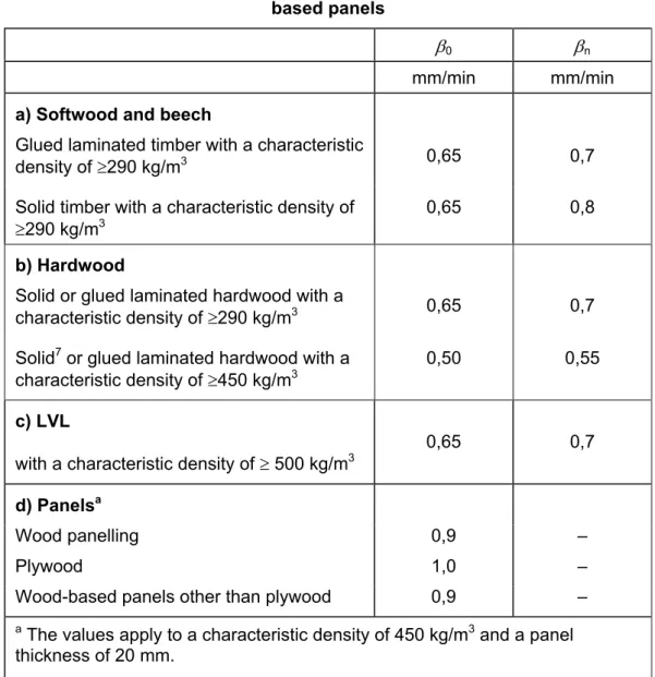
(3) For unprotected surfaces of timber design charring rates β0 and βn are given in table
3.1. The charring rates of table 3.1 apply for timber cross sections with
− a minimum residual thickness of 40 mm when charring takes place on both sides in direction of the thickness
− a minimum residual thickness of 20 mm when charring takes place on one side in direction of the thickness
(4) For solid hardwood with characteristic densities between 290 and 450 kg/m3, in table
3.1 intermediate values may be obtained by linear interpolation. Charring rates of beech should be taken as given for solid softwood.
(5) For unprotected surfaces of LVL according to prEN 13986 and prEN124-aaa, design charring rates β0 and βn are given in table 3.1. Clause 3.3.2(3) applies with respect to
minimum thicknesses of the residual cross section.
(6) When applying the basic charring rate, the shape of the char-line at corners should be assumed as circular with a radius equal to the charring depth. This is valid for radii not greater than br /2 or hr /2, whichever is the smallest, where br and hr are the width and depth
of the residual cross section respectively.
(7) For wood panelling, wood-based panels according to EN 309, EN 313-1, EN 300 and EN 316, charring rates are given in Table 3.1. The values apply to a characteristic density of 450 kg/m3 and a panel thickness of 20 mm.
(8) For other characteristic densities ρk and thicknesses hp of panels the charring rate should
be calculated as
β
0,ρ,t=
β
0k k
ρ h (3.3) with kρρ
= 450 k (3.4) = 0 1 20 p h , max h k (3.5) whereρk is the characteristic density in kg/m3
hp is the panel thickness in millimetres.
Table 3.1 – Design charring rates β0 and βn of timber, LVL, wood panelling and
wood-based panels
β0 βn
mm/min mm/min
a) Softwood and beech
Glued laminated timber with a characteristic
density of ≥290 kg/m3 0,65 0,7
Solid timber with a characteristic density of
≥290 kg/m3 0,65 0,8
b) Hardwood
Solid or glued laminated hardwood with a
characteristic density of ≥290 kg/m3 0,65 0,7
Solid7 or glued laminated hardwood with a
characteristic density of ≥450 kg/m3
0,50 0,55
c) LVL
with a characteristic density of ≥ 500 kg/m3 0,65 0,7
d) Panelsa
Wood panelling 0,9 –
Plywood 1,0 –
Wood-based panels other than plywood 0,9 –
a The values apply to a characteristic density of 450 kg/m3 and a panel
thickness of 20 mm.
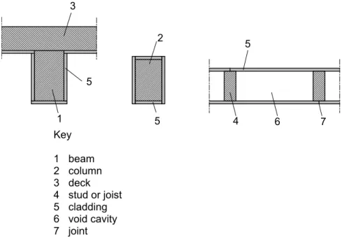
3.3.3 Protected surfaces
(1) For surfaces protected by fire protective claddings, see figure 3.1, other protection materials or by other structural members, it should be taken into account that
– the start of charring is delayed until time tch;
– the charring rate is reduced until failure time tf of the fire protection;
– the charring rate may be increased after failure time tf of the fire protection.
NOTE 1: Other fire protection are available such as intumescent coatings and impregnation. Test methods are given in ENV 13381–7
NOTE 2: The protection provided by other structural members may be terminated due to – failure or collapse of the protecting members;
– excessive deformations of the protecting member.
5 4 5 2 1 3 5 6 7 Key 1 beam 2 column 3 deck 4 stud or joist 5 cladding 6 void cavity 7 joint
Figure 3.1 — Examples of panels used as fire protective claddings
(2) For protected surfaces with failure times tfof the protection smaller than 10 minutes, the
effect of the protection should be disregarded, see figure 3.2.
(3) For failure times tf of the protection of 10 minutes or more, for the stage immediately after
failure of the protection, the charring rates of table 3.1 should be multiplied by 2 until a charring depth dchar,n of 25 mm is reached or is equal to the charring depth of an unprotected
surface, whichever is the smallest. Thereafter the charring rates of table 3.1 should be used, see figure 3.2 and 3.3.
0 10 20 30 40 Time t Charring depth dchar,n [mm] tch = tf 1 2a dchar,n = 25 mm 10 min 2b 3 Key
1 Relationship for unprotected members for charring rate βn
2 Relationship for protected members after failure of the fire protection 2a After the fire protection has fallen off and charring starts at double
rate
2b After char depth exceeds 25 mm charring rate reduces to βn
3 Relationship for protected members with failure of fire protection after 10 minutes
Figure 3.2 — Illustration of charring depth vs. time for tch = tf
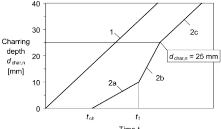
0 10 20 30 40 Time t Charring depth dchar,n [mm] tch dchar,n = 25 mm 1 2a tf 2b 2c Key
1 Relationship for unprotected members for charring rate βn
2 Relationship for protected members where charring starts before failure of protection:
2a Charring starts at tch at a reduced rate when protection is still in place
2b After protection has fallen off and charring starts at double rate 2c After char depth exceeds 25 mm charring rate reduces to βn
(4) The effect of joints of the cladding for unfilled gaps greater than 2 mm on the start of charring and, where relevant, on the charring rate before failure of the protection should be taken into account.
(5) Unless rules are given below, the following should be assessed on the basis of tests:
− the time to the start of charring tch of the member;
− the time for failure of the fire protective cladding or other fire protection material tf;
− the charring rate before failure of the protection when tf > tch.
NOTE: A test method is given in prENV 13381-7.
(6) For fire protective claddings of wood panelling and wood-based panels, the failure time should be determined as
t
f=
h
p−
β
04
(3.6)where
tf is the failure time in minutes;
β0 is the basic charring rate of the panel according to table 3.1 in mm/minute;
hp is the total cladding thicknes of all layers in millimetres.
For wood-based panels and wood panelling, it may be assumed that charring of the protected timber member starts at the failure time of the panel, i.e. tch = tf.
(7) For claddings consisting of one layer of gypsum plasterboard of type A, F or H according to prEN 520, at locations remote from panel joints, or adjacent to filled or unfilled gaps with a width of 2 mm or less, the time of start of charring may be taken as
t
ch=
2 8
,
h
p−
14
(3.7)where hp is the total thickness of panels in mm.
At locations adjacent to joints with unfilled gaps with a width of more than 2 mm, the time of start of charring should be calculated as
t
ch=
2 8
,
h
p−
23
(3.8)NOTE: Gypsum plasterboard type E, D, R and I according to prEN 520 have equal or better thermal and mechanical properties than type A and H.
(8) For claddings consisting two layers of gypsum plasterboard where both layers remain in place and will both fail simultaneously, at locations remote from panel joints in the outer layer the time of start of charring may be taken according to expression (3.7), where hp is the total
thickness of panels in mm.
At locations adjacent to joints in the outer layer, the time of start of charring should be calculated according to expression (3.8).
NOTE: For example, when the outer layer is of type F and the inner layer of type A or H, both layers will normally fall off simultaneously.
(9) For claddings consisting two layers where the layers fall off separately, expressions (3.7) and (3.8) are not valid.
NOTE: Where two layers of gypsum plasterboard type A or H are used, both layers will normally fall off at different times.
(10) Failure times of gypsum plasterboard due to mechanical degradation of the material should be determined by testing. For type A and H the failure time tf should be taken as tf =
tch.
NOTE 1: Test methods are given in EN 1363-1, EN 1365-1, EN 1365-2 and prENV 13381-7. NOTE 2: In general, failure due to mechanical degradation is dependent on temperature and size of the panels and their orientation. Normally, vertical position is more favourable than horizontal. NOTE 3: The failure time depends also on the length of fasteners, providing anchorage in unburned timber. Design rules are given in annex C (informative).
(11) For timber protected by a single layer of gypsum plasterboard type F, for tch≤t≤tf the
charring rates according to table 3.1 should be multiplied by
k
2= −
1
0,018
h
p (3.9)where
hp is the layer thickness in millimetres.
Expression (3.9) applies also for two layers of gypsum plasterboard, where the outer layer is type F and the inner layer is type A or H.
NOTE: For members in wall and floor assemblies, expressions are given in annex C (informative). (12) For beams or columns protected by rock fibre batts with a thickness of more than 20 mm and a density of more than 26 kg/m3 which remain coherent up to 1000°C the protection time
may be taken as
(
ins)
insch
=
0
,
07
h
−
20
ρ
t
(3.10)where
tch is the time of start of charring in minutes
hins is the thickness of the insulation material in millimetres
ρins is the density of the insulating material in kg/m3
3.4 Adhesives
(1)P Adhesives for structural purposes shall produce joints of such strength and durability that the integrity of the bond is maintained in the assigned fire resistance period.
NOTE: For some adhesives, the softening temperature is considerably below the charring temperature of the wood.
(2) For bonding of wood to wood, wood to wood-based materials or wood-based materials to wood-based materials, adhesives of phenol-formaldehyde and aminoplastic type according to type 1 adhesive according to EN 301 and adhesive for plywood and LVL according to EN 314 should be used.
(3) For glued-in rods, the softening temperature of the adhesive should be determined by tests.
Section 4
Design procedures for mechanical resistance
4.1 General(1) The rules of EN 1995-1-1 apply with cross sectional properties determined according to 4.2 and 4.3.
4.2 Simplified rules for cross sectional resistance 4.2.1 General
(1) The cross-sectional resistance may either be determined by the rules given in 4.2.2, or, alternatively, given in 4.2.3.
NOTE: The National choice may be given in the National annex.
4.2.2 Reduced cross section method
(1) An effective cross section should be calculated by reducing the initial cross section by the effective charring depth (see figure 4.1 line 3)
ef char 0 0
d = d
,n+ k d
(4.1)with
d0 = 7 mm
dchar,n according to expression (3.2) or calculated according to the rules given in 3.3.3
k0 according to table 4.1 and (3), see figure 4.2a.
NOTE: It is assumed that the reduction of strength and stiffness properties of the material close to the char line is allocated to the layer of thickness k0d0, while the strength and stiffness properties
of the remaining effective cross section are assumed to be unreduced.
1
2
3
dchar,n k0d0 def Key1 Initial surface of member 2 Border of residual cross section 3 Border of effective cross section
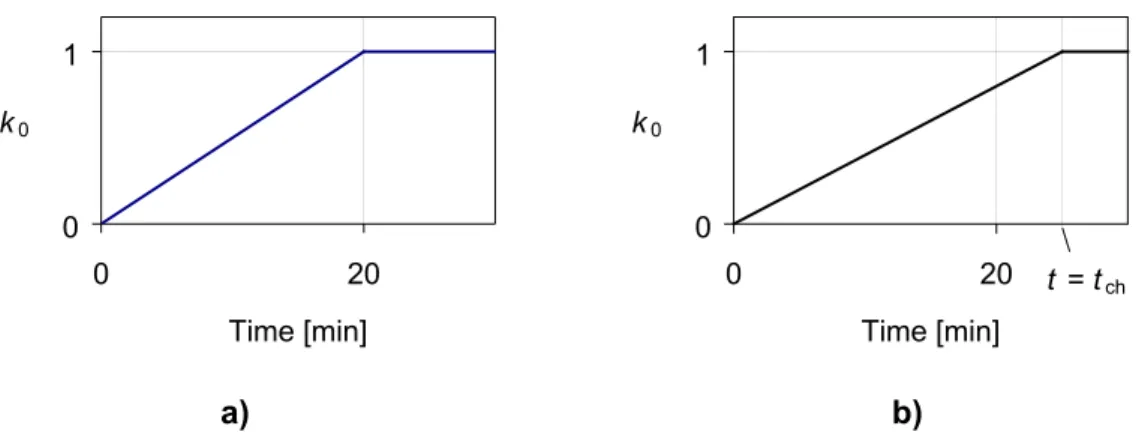
Table 4.1 — Determination of k0 for unprotected surfaces with t in minutes (see figure
4.1a)
k0 t < 20 minutes t/20 t≥ 20 minutes 1,0
(2) For protected surfaces with tch > 20 minutes or tf > 20 minutes, it should be assumed that
k0 varies linearly from 0 to 1 during the time interval from t = 0 to t = tch or t = tf, whichever is
the smallest, see figure 4.2b. For protected surfaces with tch≤ 20 minutes or tf≤ 20 minutes
table 4.1 applies. 0 1 0 20 Time [min] k0 0 1 0 20 Time [min] k0 t = tch a) b)
Figure 4.2 — Variation of k0: a) for unprotected members, b) for protected members
(shown for tch < tf)
(3) The design strength and modulus of elasticity respectively of the effective cross section should be taken according to expressions (2.1)-(2.2) with kmod,fi = 1,0
4.2.3 Reduced properties method
(1) The following rules should be applied to rectangular cross sections of softwood exposed to fire on three or four sides and round cross sections exposed along its whole perimeter.
(2) The residual cross section should be determined according to 3.3.
(3) For t ≥ 20 minutes, the modification factor for fire kmod,fi, see 2.3 (1)P, should be taken
as follows (see figure 4.3):
− for bending strength:
k p A mod,fi r =10− 1 200 , (4.2)
− for compressive strength:
k p A mod,fi r =10− 1 125 , (4.3)
− for tensile strength and modulus of elasticity: k p A mod,fi r =10− 1 330 , (4.4) where
p is the perimeter of the fire exposed residual cross section in metres Ar is the area of the residual cross section in m2
(4) For unprotected and protected members, for time t = 0 the modification factor for fire should be taken as kmod,fi = 1. For unprotected members, for 0 ≤t ≤ 20 min the modification
factor may be determined by linear interpolation.
0 0,2 0,4 0,6 0,8 1 0 20 40 60 80 100 p / Ar
[m-1] kmod,fi 1 2 3 Key
1 Tensile strength, Modulus of elasticity 2 Bending strength
3 Compressive strength
4.3 Simplified rules for analysis of structural members and components
4.3.1 General
(1) Compression perpendicular to grain may be disregarded.
(2) Shear may be disregarded in rectangular and circular cross sections. For notched beams it should be verified that the residual cross section in the vicinity of the notch is at least 60 % of the cross section required for normal temperature design.
4.3.2 Beams
(1) Where bracing fails during the relevant fire exposure, lateral buckling should be considered as for an unbraced member.
4.3.3 Columns
(1) Where bracing fails during the relevant fire exposure, buckling should be considered as for an unbraced member.
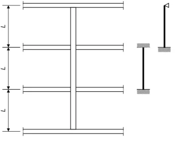
(2) More favourable boundary conditions compared to normal temperature design may be assumed for a column in a fire compartment which is part of a continuous column in a non-sway frame. In intermediate storeys the column may be assumed as completely fixed at both ends, in the top storey the column may be assumed as completely fixed at its lower end, see figure 4.4. The column length should be taken as the system length L of the storey.
L
L
L
Figure 4.4 — Continuous column
4.3.4 Mechanically jointed members
(1)P For mechanically jointed members, the reduction of slip moduli in the fire situation shall be taken into account.
(2) The slip modulus Kfi for the fire situation should be determined as
where
Kfi is the slip modulus in the fire situation in N/mm
Ku is the slip modulus at normal temperature for the ultimate limit state according to EN
1995-1-1 2.2.2(2) in N/mm
ηf is a conversion coefficient according to table 4.2.
Table 4.2 — Conversion factor ηf
Nails 0,2
Bolts, dowels, connectors
0,67
4.3.5 Bracings
(1) Where members in compression or bending are designed taking into account the effect of bracing, it should be verified that the bracing does not fail during the required duration of the fire exposure.
(2) The bracing may be assumed not to fail if the residual width and area is 60 % of its initial width and area that are required with respect to normal temperature design, and is fixed with nails, screws, dowels or bolts.
4.4 Advanced calculation methods
4.4.1 General
(1) Advanced calculation models may be used for individual members, parts of a structure or for entire structures.
− (2) Advanced calculation methods may be applied for :the determination of the charring depth
− the development and distribution of the temperature within structural members (thermal response model);
− the evaluation of structural behaviour of the structure or of any part of it (structural response model).
(3) The ambient temperature should be taken as 20°C.
4.4.2 Thermal response
(1) Advanced calculation methods for thermal response should be based on the theory of heat transfer.
(2) The thermal response model should take into account:
− the variation of the thermal properties of the material with the temperature.
NOTE: Where thermal models do not take into account phenomena such as increased heat transfer due to mass transport, e.g. due to the vaporisation of moisture, or increased heat transfer due to cracking which causes heat transfer by convection and/or radiation, the thermal properties are often modified in order to give results that can be verified by tests.
(4) The influence of any moisture content of wood and of protection made of gypsum plasterboard should be taken into account.
4.4.3 Structural response
(1) General calculation methods should take into account the changes of mechanical properties with temperature and, where relevant, also of moisture.
(2) The effects of transient thermal creep should be taken into account. For timber and wood-based materials, special attention should be drawn to transient states of moisture.
NOTE: The mechanical properties of timber given in annex B include the effects of thermal creep and transient states of moisture.
(3) For materials other than timber or wood-based materials, the effects of thermally induced strains and stresses both due to temperature rise and due to temperature gradients, should be taken into account.
(4) The structural response model should take into account the effects of non-linear material properties.
Section 5
Design procedures for wall and floor assemblies
5.1 General(1) The rules in this subclause apply to load bearing (R), separating (EI), and load bearing and separating (REI) constructions. For the separating function the rules apply for a maximum standard fire resistance not more than 60 minutes.
5.2 Analysis of load bearing function
(1) For assemblies with void cavities, the rules of section 3 and 4 should be used. NOTE: A design method for wall and floor assemblies with insulation in the cavities is given in annex C (informative)
(2)P Non-separating load-bearing constructions shall be assumed to be exposed to fire on both sides at the same time.
(3) Where wood-based panels or wood panelling are used for stiffening or bracing the load bearing timber frame, they should have a residual thickness of at least 60 % of the thickness required for normal temperature design; else the frame should be analysed as unbraced, see 4.3.5.
5.3 Analysis of separating function
5.3.1 General
(1)P The fixing of the panel on the unexposed side of the assembly shall be secured into unburnt timber.
(2) The centre-line of the fastener should be at least at a distance of 5 mm from the char-line. (3) Requirements with respect to insulation (criterion I) are assumed to be satisfied provided that detailing is carried out according to subclause 7.1.
(4) Requirements with respect to integrity (criterion E) are assumed to be satisfied where the requirements with respect to insulation (criterion I) are satisfied provided that detailing is carried out according to subclause 7.1. It should also be ensured, that panels remain fixed to the timber frame on the unexposed side.
(5) The rules apply to timber frame members, claddings made of wood-based panels
according to EN 13986 and gypsum plasterboard of type A, F and H according to prEN 520. For other materials, integrity should be determined by testing.
NOTE: See Note 1 of 3.3.3(7).
(6) For separating members it should be verified that
t
ins≥
t
req (5.1)where
tins is the time to reach the temperature increase on the unexposed side given in 2.1.2(3);
5.3.2 Simplified method for the analysis of insulation 5.3.2.1 General
(1) The value of tins may be calculated as the sum of contributions of the individual layers
used in the construction, according to
t
inst
ins,0,ik
posk
ij
=
∑
(5.2)where
tins,0,i is the basic insulation value of layer “i” in minutes, see 5.3.2.2;
kpos is a position coefficient, see 5.3.2.2;
kj is a joint coefficient, see 5.3.2.2(8) - (10).
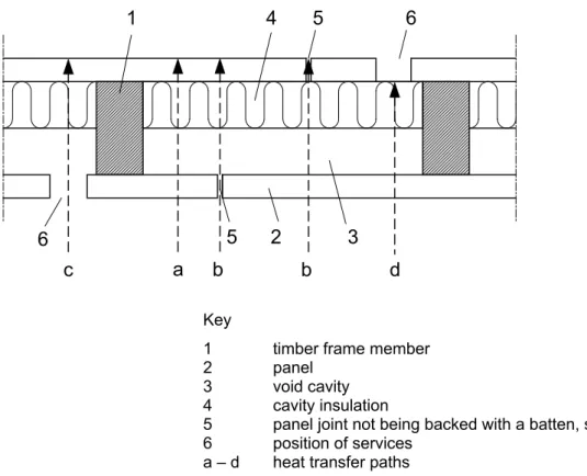
The relevant number of layers should be taken according to table 5.1 and figure 5.2. NOTE: A joint does not have an effect on the performance if it is backed with a batten or a structural element, which will prevent the travel of hot gases into the structure.
Table 5.1 — Heat transfer path through layer to be taken into account Temperature rise on
unexposed side
°C
Heat transfer path according to figure
5.1
General construction 140 a
Joints 180 b
Key
1 timber frame member
2 panel
3 void cavity 4 cavity insulation
5 panel joint not being backed with a batten, stud or joist 6 position of services
a – d heat transfer paths
Figure 5.1 — Illustration of heat transfer paths through separating construction 5.3.2.2 Basic insulation values, position coefficients and effect of joints
(1) The values given in this subclause may be applied for verification of fire resistance times up to 60 minutes.
(2) Basic insulation values of panels should be determined from the following expressions: – for plywood with a characteristic density of 450 kg/m3
t
ins,0=
0 95
,
h
p−
0 3
,
t
ins,0=
0 95
,
h
p (5.3) – for particleboard and fibreboard with a characteristic density greater or equal 600 kg/m3t
ins,0=
11
,
h
p+
0 4
,
t
ins,0=
11
,
h
p (5.4) – for wood panellling with a characteristic density greater or equal 400 kg/m3t
ins,0=
0 5
,
h
p+
0 2
,
t
ins,0=
0 5
,
h
p (5.5) – for gypsum plasterboard of type A, F, R and Ht
ins,0=
14
,
h
p+
0 4
,
t
ins,0=
14
,
h
p (5.6) wheretins,0 is the basic insulation value in minutes
hp is the panel thickness in millimetres.
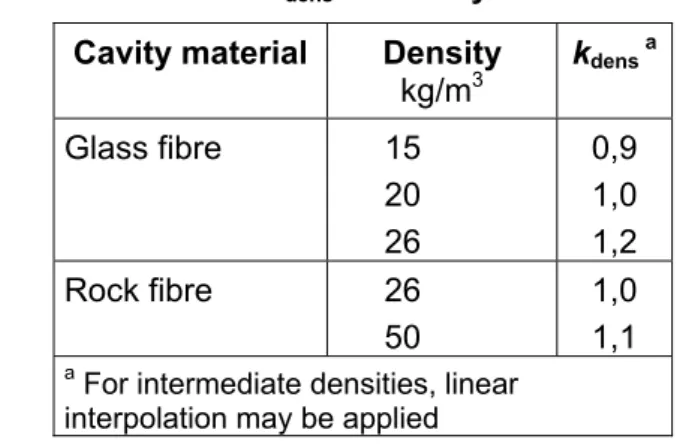
(3) Where cavities are partially or completely filled with insulation made of glass or rock fibre, basic values of the insulation should be determined as:
– for rock fibre
b a d c 1 2 5 6 6 3 4 b 5
t
ins,0,i= 0,2
h
insk
dens (5.7) – for glass fibret
ins,0,i= 0,1
h
insk
dens (5.8)where
hins is the insulation thickness in millimetres
kdens should be taken from table 5.2.
(4) For void cavities of depth between 45 and 200 mm the basic insulation value should be taken as tins,0 = 5,0 min.
(5) For walls with single layered claddings, position coefficients for panels on the exposed side of walls should be taken from table 5.3, and for panels on the unexposed side of walls from table 5.4, with following expressions:
k
pos=
R
S
h
p+
T
min
0 02
,
0 54
,
1
(5.9)k
pos=
0 07
,
h
p−
0 17
,
(5.10)The position coefficients for voids and insulation layers is 1,0.
(6) For walls with double layered claddings, see figure 5.2, position coefficients should be taken from table 5.5.
(7) For floors exposed from below, the position coefficients for the exposed panels given in tables 5.3 and 5.5 should be multiplied by 0,8.
(8) The joint coefficient kj should be taken as
k
j=
1
(6.11)for the following:
panel joints fixed to a battens of at least the same thickness or a structural element;
wood panelling.
NOTE: For wood panelling the effect of joints is included in the basic insulation values tins,0 given by
expression (5.5).
(9) For panel joints not fixed to a batten, the joint coefficient kj should be taken from tables
5.6 and 5.7.
(10) For butt jointed insulation batts or insulation batts with a density of greater than 30 kg/m3
butted against the timber frame member, the joint coefficient may be taken as kj = 1,
Table 5.2 — Values of kdens for cavity insulation materials
Cavity material Density
kg/m3 kdens a Glass fibre 15 20 26 0,9 1,0 1,2 Rock fibre 26 50 1,0 1,1
a For intermediate densities, linear
interpolation may be applied
Table 5.3 — Position coefficients kposfor single layered panels on the exposed side
Position coefficient for panels backed by
Panel Density
kg/m3
Thickness
mm
rock or glass fibre void
Plywood ≥ 450 9 - 25 Expression (5.9) 0,8 Particleboard, fibreboard ≥ 600 9 - 25 Expression (5.9) 0,8 Wood panelling ≥ 400 15 - 19 Expression (5.9) 0,8 0,8 Gypsum plasterboard type H type A type F ≥ 740 ≥ 680 ≥ 830 9 - 15 Expression (5.9) 0,8