Old Cedar Avenue Bridge over Long Meadow Lake
(Bridge No. 3145)
FINAL
The City of Bloomington, MN
July 2014 SRF No. 8418
Old Cedar Avenue Bridge over
Long Meadow Lake (Bridge No. 3145)
Prepared forCity of Bloomington
Certifications
We hereby certify that this report was prepared by me or under my direct supervision and that I am a duly Licensed Professional Engineer under the laws of the State of Minnesota.
Jamison Beisswenger, PE ________________________ _____________________ License No. 44648 Matthew J. Cramer, PE ________________________ _____________________ License No. 43517 Thomas P. Murphy, PhD, PE ________________________ _____________________ License No. 51244
I hereby certify that this report was prepared by me or in collaboration with me and that I meet the Secretary of the Interior’s Professional Qualifications Standards for Historian and Architectural Historian. Charlene Roise ____________________________ _____________________ 6/17/2014 6/17/2014 6/17/2014 6/17/2014
List of Figures ... ii
List of Tables ... iv
Introduction/Project Background ... 1
Purpose and Need ... 2
Purpose/Objectives ... 2
Need/Deficiencies ... 2
Character Defining Features, Historic Fabric and Historic Integrity ... 3
Truss Bridge Nomenclature ... 4
Proposed Cross-Section Geometry ... 7
Evaluation of Load Capacity ... 8
Proposed Loading Criteria ... 8
Existing Load Capacity ... 9
Proposed Rehabilitation ... 13
Deck ... 13
Riveted Connections ... 14
Truss Members ... 25
Gusset Plates ... 33
Floor System Members ... 37
Lower Lateral Bracing ... 39
Bearings ... 39
Railing ... 42
Abutment Piers ... 45
Piers 2-5 ... 46
Surface Coatings and Treatments ... 52
Conclusion ... 53
Summary of Recommended Rehabilitation ... 53
Compliance with Section 106 ... 54
List of Figures
Figure 1: General Truss Nomenclature1 ... 4
Figure 2: Gusset Plate Nomenclature (Gusset Elevation) ... 5
Figure 3: Gusset Plate Nomenclature (Gusset Cross-Section) ... 5
Figure 4: Batten Plates and Member Lacing ... 6
Figure 5: Truss Panel Point Designations ... 6
Figure 6: Original Cross-Section Geometry ... 7
Figure 7: Proposed Cross-Section Geometry ... 7
Figure 8: Span 2, North Truss Gusset Plates –Normal Weight vs. Lightweight Concrete Deck ... 11
Figure 9: Span 2, South Truss Gusset Plates – Normal Weight vs. Lightweight Concrete Deck ... 11
Figure 10: Span 3, North Truss Gusset Plates – Normal Weight vs. Lightweight Concrete Deck ... 11
Figure 11: Span 3, South Truss Gusset Plates –Normal Weight vs. Lightweight Concrete Deck ... 11
Figure 12: Location of Critical Deterioration at L0/L0’ Gussets ... 12
Figure 13: Location of Critical Deterioration at L3/L3’ Splice Plate ... 12
Figure 14: Fastener Types ... 14
Figure 15: Acorn vs. Hex Style Nut ... 14
Figure 16: Low Profile Electric Shear Wrench ... 16
Figure 17: Low Profile Hand Operated Shear Wrench ... 16
Figure 18: Gusset Plate Fasteners – Button Head Facing Outboard ... 17
Figure 19: Gusset Plate Fasteners – Button Head Facing Inboard ... 18
Figure 20: View of Gusset Plates from Deck ... 18
Figure 21: Gusset Plate Elevation Rendering – Original Rivets ... 19
Figure 22: Gusset Plate Elevation Rendering – Button Head Bolts with Hex Nuts ... 20
Figure 23: Gusset Plate Plan Rendering –Button Head Bolt with Hex Nuts ... 20
Figure 24: Hex Head Nut Caps ... 21
Figure 25: Gusset Plate Elevation Rendering –Button Head Bolts with Caps over Hex Nut ... 22
Figure 26: Gusset Plate Plan Rendering –Button Head Bolts with Caps over Hex Nut ... 22
Figure 27: Gusset Plate Plan Rendering – Hex Head Bolts with Hex Nut ... 23
Figure 28: Portal Brace Impact Damage – L0-U1, Span 4 North ... 26
Figure 29: Diagonal Impact Damage – L4-U3, Span 4 South ... 26
Figure 30: Member Deterioration: L0-L2 North- Span 1 ... 27
Figure 34: Member Deterioration: U3’-L4 North – Span 2 ... 29
Figure 35: Proposed Member Repair: U3’-L4 North – Span 2 ... 29
Figure 36: Member Damage: L3’-U2’ South – Span2 ... 30
Figure 37: Proposed Member Repair: L3’-U2’ South – Span2 ... 30
Figure 38: Member Damage: U4-L3’ South – Span 3 ... 31
Figure 39: Proposed Member Repair: U4-L3’ South – Span 3 ... 31
Figure 40: Member Deterioration: L3-L3’ North – Span 5 ... 32
Figure 41: Member L3-L3’ Shop Drawing (to be used for replacement member fabrication) ... 32
Figure 42: Typical Pack Rust between Gusset and Truss Member ... 33
Figure 43: Gusset L0/L0’ Shop Drawing (to be used for gusset fabrication) ... 34
Figure 44: Typical Inboard Splice Plate ... 35
Figure 45: Proposed Repair: Splice Plate Replacement at Gussets L2/L2’ and L3/L3’ ... 35
Figure 46: Bolt Installation on Rough Surface ... 36
Figure 47: Gussets with Inadequate Surface Conditions for Bolting ... 37
Figure 48: Gussets with Acceptable Surface Conditions for Bolting ... 37
Figure 49: Typical Floor System Member Condition ... 38
Figure 50: Lower Lateral Bracing Connection (showing complete section loss) ... 39
Figure 51: Original Bearing Assembly (Expansion Assembly Shown) ... 40
Figure 52: Typical Condition of Fixed and Expansion Bearing Assembly ... 41
Figure 53: Replacement Fixed Bearing ... 41
Figure 54: Replacement Expansion Bearing ... 42
Figure 55: Original & Replacement Railing Cross-Sections ... 43
Figure 56: Photo of Existing Railing ... 44
Figure 57: Rendering of Proposed Railing ... 44
Figure 58: Abutment Pier 1 – Proposed Rehabilitation ... 45
Figure 59: Abutment Pier 6 – Proposed Rehabilitation ... 46
Figure 60: Typical Pier Components ... 47
Figure 61: Typical Freeze-Thaw Deterioration at the Water Line ... 47
Figure 62: Typical Freeze-Thaw Deterioration at the Pier Cap ... 48
Figure 63: General Pier Deterioration (Pier 4) ... 48
Figure 64: Typical Pier Repair Elevation ... 50
Table 1: Truss Members with Preliminary Rating Factors < 1.0 ... 10
Table 2: Estimated Deck Concrete Material Costs2 ... 13
Table 3: Fastener Location Matrix ... 24
Table 4: Truss Members with Impact Damage ... 25
Table 5: Combination Bike/Pedestrian Railing Design Requirements ... 42
Table 6: Recommended Rehabilitation Summary ... 53
At the southern edge of the Twin Cities, the Minnesota River passes through a broad, deep valley and separates Hennepin County to the northwest from Dakota County to the southeast. Long Meadow Lake extends between the river channel and the northwest bank. The community of Bloomington, which is situated on the north edge of the lake, had been established in the mid-nineteenth century and grew into a major city in the following century.
While the Minnesota River served as a transportation corridor for Native Americans and early settlers, it was increasingly perceived as more of an impediment than an asset as the area developed. A series of ferries provided passage across the river by the 1850s. These could not keep up with the demand by the 1880s, however, when pressure grew for the construction of a more reliable crossing. By the end of that decade, the state legislature had passed a law to fund two bridges over the Minnesota River, connecting Hennepin County with Dakota and Scott counties, respectively. Although the commissioners for Hennepin and Dakota counties determined that their bridge would extend Cedar Avenue, an existing road that began in Minneapolis and continued through Bloomington, some local groups lobbied for alternative locations. The Cedar alignment ultimately prevailed though, and in 1891 an iron swing span was erected over the Minnesota channel, with a wood trestle over Long Meadow Lake18.
Both the volume and character of traffic changed radically over the next decades as cars and trucks displaced horses and wagons on America’s roads. The need to improve road systems was acknowledged by both the public and private sectors, leading to the creation of federal and state highway departments and community “Good Roads” groups. With pressure from local commercial interests, the Minnesota legislature authorized funding for upgrading the Cedar Avenue crossing in 1918. The swing span was considered adequate, but the trestle over Long Meadow Lake was targeted for replacement. Hennepin County oversaw the planning and construction, with staff surveyor E. J. Miller designing a bridge with five identical, steel, Camelback through-truss spans. A Saint Paul contractor, the J. W. Hoy Company, took on the challenging task of installing the substructure through the marshy terrain in 1919. Historical accounts give conflicting information on what firm was responsible for installing and fabricating the superstructure; Minnesota Steel and Machinery Company’s name is on the shop drawings, but other sources credit the Saint Paul branch of the Illinois Steel Bridge Company. When the bridge opened to traffic on Thanksgiving 1920, it was the longest structure of its type in Minnesota18.
While immediately earning an important place in the region’s road system, the bridge also was quick to have problems. Unstable conditions at the piers and abutments because of swampy soil conditions were exacerbated when the gravel approach road on the Bloomington end was paved in 1922 with no provision for pavement expansion. In February 1923, only a few years after the bridge had gone into service, an engineering study reported: “Pier No. 6 on the Minnesota River end is stable and has not moved to any considerable extent. Pier #1 on the Minneapolis end has moved a considerable distance.” Repairs were apparently completed later that year17.
Pier 1 required repairs again in 1957. In the meantime, the volume of traffic on the bridge was causing other deterioration. By 1961, the concrete deck was falling apart, leading to its replacement with a wood deck. The original metal pipe railings were another casualty. Maintenance records document the repeated need to repair or replace, in kind, the utilitarian rails after they were damaged by cars and trucks. Truss members were subject to similar disfiguration from passing vehicles. Changing transportation systems, including the construction of nearby interstate highway corridors, led the Minnesota Department of Transportation to transfer ownership of the Cedar Avenue
bridges to Bloomington in 1981. The swing span was removed around that time. The Long Meadow Lake Bridge continued to serve vehicles until 1993, when it was restricted to pedestrians and bicyclists. Even these uses were prohibited in 2002, following the recommendation of an engineering study.
Birdwatchers, bicyclists, pedestrians, and others encouraged the city to rehabilitate the bridge and return it to non-vehicular use. To facilitate this outcome, the bridge was listed in the National Register of Historic Places on May 28, 2013, under Criterion C for its statewide significance in the area of engineering. The nomination noted that the bridge “meets the registration requirements of the Multiple Property Documentation Form for the statewide context of ‘Iron and Steel Bridges in Minnesota.’ Specifically, it is a bridge that exhibits exceptional engineering skill to meet unusual site conditions.” The nomination established the period of significance as 192018.
Since the Long Meadow Lake Bridge is listed in the National Register, work on the bridge that receives federal funding or is federally licensed (such as a U.S. Army Corps of Engineers permit) is subject to review under Section 106 of the National Historic Preservation Act. The federal agency responsible for the funding/licensing must consider the effects of the project on historic resources and attempt to avoid or minimize potential adverse effects on these resources.
The bridge is now closed to all traffic because of its deteriorated condition. Rehabilitating the bridge will allow it to return to service for pedestrians and bicycles. While the bridge will no longer carry vehicles (other than those used for maintenance and emergencies), the resumption of use will facilitate its long-term preservation. The proposed project will follow the Secretary of the Interior’s Standards for the Rehabilitation of Historic Properties, so it will have a beneficial effect on the historic resource.
Purpose and Need
The project Purpose and Need as defined in the Project Memorandum is as follows:
Purpose/Objectives
To provide a non-motorized crossing of the Minnesota River by restoring a local and regionally important trail connection across Long Meadow Lake, and to address current deficiencies through repairs to the existing structure that preserve the historic structure and minimize future maintenance costs to the extent possible.6
Need/Deficiencies
The existing bridge is a fracture critical, non-redundant structure that is in poor condition, which has resulted in its being closed to all users since 2002. There is currently no connection between existing regional trail systems. For the public to make a connection across the Minnesota River or Minnesota Valley National Wildlife Refuge to trails on either side, a minimum four-mile detour is required. A connection in this location is important not only to the City of Bloomington, but to the U.S. Fish and Wildlife Service (owner and operator of the Refuge), the DNR (state park and trail connections), Dakota and Hennepin Counties, and other neighboring cities such as Eagan and Burnsville. This connection is also important to bicycle commuters, recreational enthusiasts, and visitors to the Refuge and nearby Fort Snelling State Park.6
Character Defining Features, Historic Fabric and Historic Integrity
The National Register nomination for Bridge 3145 makes the case for the bridge’s eligibility for listing under two criteria. Under Criterion A, the bridge is recognized as a significant crossing. Under Criterion C, it is significant for representing a type of design, namely the Camelback through truss.
For the engineering significance (Criterion C), the character-defining features include the design and function of the trusses individually and combined. Hence, all of the components that are essential to the structure are character-defining.
The original concrete deck, which is essential to the bridge’s function, has been replaced by a timber deck. This detracts from the integrity of the bridge, although not enough to disqualify the bridge from its National Register status. Restoring the deck to concrete in its historic dimensions would benefit the bridge and help mitigate other changes that might be necessary or prudent for the rehabilitation, such as replacing some rivets with bolts or reducing the number of stringers supporting the deck if structurally appropriate.
Secondary features that contribute to the bridge’s character include railings and concrete. In both cases, these features have little, if any, of their original materials, but replacements have been done with similar materials and compatible designs:
Railings: Maintenance records reveal that sections of the pipe railings were replaced in kind, with great regularity, to repair damage from vehicular traffic. Virtually none of the railings are original.
Concrete substructure: The National Register established the bridge’s period of significance as a single year, 1920. By the following year, the north abutment had moved 4-1/2 inches due to unstable soil conditions, and this, in turn, affected the pier alignment. To address this ongoing problem, sections of the concrete substructure were repaired as early as 1923, and the north abutment was apparently reconstructed at that time.
Because the original materials of these secondary features have been replaced in whole or in part, the impact of installing new railings and concrete substructure on the bridge’s overall integrity is minor, assuming that the replacements are done in kind (using modern materials/technology/standards when appropriate).
In the National Register bulletin “How to Apply the National Register Criteria or Evaluation,” seven aspects of integrity are identified: location, design, setting, materials, workmanship, feeling, association. Bridge 3145 retains most of these, from the perspective of both Criterion A and Criterion C. The bridge is in its original location, and the five-span, Camelback through-truss structure remains essentially unaltered from the time of its construction (except for the deck), maintaining integrity of design, materials, and workmanship. While it is difficult to authoritatively establish the character of vegetation in the vicinity in 1920, the setting was clearly compromised by the construction of the Highway 77 Bridge just downstream in the late 1970s. The location is otherwise rather isolated, which helps to absorb the impact of the highway bridge on the setting of Bridge 3145. The setting reinforces the bridge’s expression/feeling of the early twentieth century. The swing span that crossed the river channel has been removed, so the association of the bridge and the historic river crossing is weakened under Criterion A. All in all, though, the historic integrity of the bridge for its engineering significance is very good. Rehabilitating the bridge for pedestrian and bicycle use will strengthen its integrity by restoring its role as part of a transportation corridor and major river crossing, paired with the modern Highway 77 Bridge.
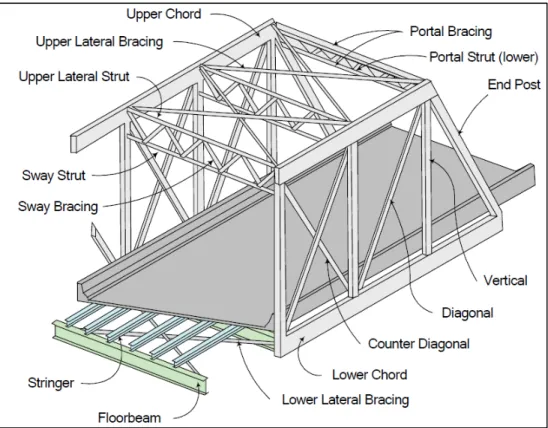
Truss Bridge Nomenclature
Throughout this report, elements of the structure are referred to using the technical definitions provided by FHWA’s Bridge Inspector’s Reference Manual. Figure 1 indicates the general nomenclature used for common truss elements.
Truss and gusset plate components are identified by their location relative to the bridge deck. Interior components are those adjacent to the bridge deck, while exterior components are those on the outside of the bridge. Each interior and exterior component also has a face which relates to its position relative to the connection. Inboard faces are those between each gusset, while outboard faces are those on the outside of each connection. Figure 2 and Figure 3 identify the general nomenclature used for a typical gusset plate connection.
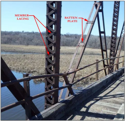
Figure 4 identifies the batten plates and lacing members found on Bridge 3145.
In addition to the standard truss nomenclature, specific element locations are referred to by truss panel points. Figure 5 indicates the panel point designations used throughout this report.
Figure 2: Gusset Plate Nomenclature (Gusset Elevation)
Figure 4: Batten Plates and Member Lacing
Figure 5: Truss Panel Point Designations
MEMBER
LACING BATTEN
Proposed Cross-Section Geometry
Selection of the proposed cross-section geometry was based on meeting the project’s purpose and need, preserving the historic integrity of the bridge and providing adequate capacity to support the proposed loading criteria. The recommended deck width, thickness and curb height were selected to closely approximate that of the original deck cross-section (Figure 6). The proposed deck section is shown in Figure 7. Under this rehabilitation, striping between the each bike lane and between the pedestrian walkways and the bike lanes is proposed.
Figure 6: Original Cross-Section Geometry
Evaluation of Load Capacity
A preliminary structural evaluation was conducted to determine the feasibility of the existing bridge to support the proposed loading criteria. In order to determine the location and extent of repairs, two deck systems were evaluated. The following was assumed for each system:
Original Deck System: 5.5 inch thick, normal weight concrete deck with a 2-inch asphalt overlay
(Deck Weight = ~90 pounds per square foot)
Lightweight Deck System: ±7 inch thick, light weight deck system (Deck Weight = ~65 pounds per square foot)
A Design-Load Rating was performed for each truss member and gusset plate in accordance with AASHTO’s Manual for Bridge Evaluation using the Load and Resistance Factor Rating (LRFR) method. The Design-Load Rating calculates a rating factor for each element in order to assess the performance of the existing bridge utilizing modern design loadings and standards.
Members with rating factors that fall below 1.0 do not have adequate capacity to support the proposed loading criteria.
Proposed Loading Criteria
Permanent Loads
Permanent Loads (also referred to as dead loads) are loads which do not vary with time upon completion of construction. Permanent loads for Bridge No. 3145 include the weight of all components of the trusses, deck, floor system, railings and substructures.
Live Loads
Live Loads are loads due to pedestrian and vehicle traffic which vary over the life of the structure. For Bridge No. 3145, these loads include the following:
Pedestrian Loads
Section 3.1 of AASHTO’s LRFD Guide Specifications for the Design of Pedestrian Bridges, states that pedestrian bridges shall be designed for a uniform pedestrian loading of 90 psf.
Vehicle Load
Section 3.2 of AASHTO’s LRFD Guide Specifications for the Design of Pedestrian Bridges, states that pedestrian bridges shall be designed for a H10 maintenance vehicle when the clear deck width is larger than 10 feet. This load shall not be placed in conjunction with the pedestrian load and need not include a dynamic load allowance.
Special Vehicle Loads
In addition to AASHTO specified vehicle loads, the bridge will accommodate specific inspection, maintenance and emergency vehicles. These vehicles all produce load effects less than that of the H10 (20,000 pound) maintenance vehicle and include the following:
MnDOT’s MOOG Inspection Access Vehicle (Unit No. 209595); Weight = 6,600 pounds
City of Bloomington’s sidewalk plow/broom; Weight = 6,000 pounds
City of Bloomington’s tenant industrial ride on sweeper
Total weight = 6,500 pounds + 2,000 pounds of sweepings = 7,500 pounds
City of Bloomington fire equipment truck: 1 ton pickup truck w/ 250 gallons of water. Total Weight = 10,000 pounds
Other Loads
Additional loads which will be accounted for in final design included loads due to earth, wind, ice and thermal expansion/contraction.
Existing Load Capacity
Existing member capacities were determined using the procedures defined in AASHTO’s LRFD Bridge Design Specifications and AASHTO’s Manual for Bridge Evaluation. In all truss members and gussets, the 90psf pedestrian load produced greater load effects than the H10 truck loading. Initially, rating factors were developed assuming an ‘as-built’ condition without accounting for member deterioration or damage. Steel section loss measurements were then used to determine a rating factor for each element based on the current ‘as-inspected’ condition.
The following is a summary of the preliminary structural evaluation:
Truss Members
For both deck types, preliminary rating factors were calculated to be greater than 1.0 in both the ‘as-built’ and ‘as-inspected’ condition for nearly all members. Members with a calculated rating factor less than 1.0 have suffered extensive deterioration or damage and are listed in Table 1.
Table 1: Truss Members with Preliminary Rating Factors < 1.0 Span
No. Truss Member
Normal Weight Deck Rating Factor
Lightweight Deck
Rating Factor Comments
1 North L0-L2 0.82 0.98 Member has 100% section loss over 6” of web and 50% section loss on the flanges 1 North L0-U1 0.49 0.74 Member has 75% loss on inboard web at the gusset plate connection 2 North U3’-L4 0.96 1.15 Members have 1/8” loss over all legs of the outboard angle
2 South L3’-U2’ 0 0 Member has cracked at first rivet on gusset L3’
3 South U4-L3’ 0 0 Member has cracked at first rivet on gusset L3’
5 North L3-L3’ 0.84 1.01 Member has 1/8” section loss of the web and areas of 100% section loss on the flanges
Gussets
Preliminary rating factors for the gussets were calculated for the ‘as-built’ condition. All gussets were found to have ratings greater than 1.0.
Evaluating the section loss for each gusset and calculating an associated ‘as-inspected’ rating factor is a time consuming effort. Therefore, in order to gain a general understanding of the capacity of existing gusset plates, preliminary rating factors were calculated for two representative spans (Spans 2 and 3) utilizing the ‘as-inspected’ condition. More refined rating factors for each gusset in all spans will be calculated in final design. The location of gussets with rating factors below 1.0 for both the normal weight and lightweight concrete decks are indicated as follows in Figure 8 through Figure 11:
Figure 8: Span 2, North Truss Gusset Plates –Normal Weight vs. Lightweight Concrete Deck
Figure 9: Span 2, South Truss Gusset Plates – Normal Weight vs. Lightweight Concrete Deck
Figure 10: Span 3, North Truss Gusset Plates – Normal Weight vs. Lightweight Concrete Deck
Section loss of the gusset, along the tops of the bottom chords, is causing rating factors less than 1.0 for gusset L0/L0,’ as shown in Figure 12. Deterioration of the inner splice plate and lower portion of the gusset plate is the cause of the rating factors less than 1.0 for gussets L2/L2’ and L3/L3’ as shown in Figure 13. The remaining gussets at L1/L1’ and L4/L4’ were found to have rating factors above 1.0 for the representative spans.
Figure 12: Location of Critical Deterioration at L0/L0’ Gussets
Proposed Rehabilitation
Deck
The existing timber deck is not original, is not considered historic fabric and is in critical condition. Therefore, the deck is recommended for replacement under this rehabilitation.
The original deck cross section (Figure 6) consisted of a 5.5-inch concrete slab with a 2-inch bituminous wearing surface. Six-inch wide curbs were formed using 15-inch deep steel channel sections. In order to preserve historic integrity, the deck cross section will be constructed with material and a geometry that closely replicates that of the original bridge.
The selection of a replacement deck section is a balance between the desire to preserve the historic integrity of the bridge while minimize impacts to the character-defining feature of the truss structure. The preliminary analysis indicates that rating factors are approximately 15-20% higher for a lightweight deck over a normal weight concrete deck. Although the use of a lightweight deck may not significantly reduce the number and extent of repairs required under this rehabilitation, it would provide an additional factor of safety against future deterioration.
The primary disadvantage of lightweight concrete is the increase material cost when compared with normal weight concrete. Additional costs due to delivery, placement, forming and rebar are not significant between the two concrete types. Table 2 compares the material costs of both normal weight and lightweight concrete.
Table 2: Estimated Deck Concrete Material Costs2
Deck Type Estimated Concrete Material Cost ($/yd3) Estimated Deck Concrete Quantity (yd3) Estimated Total Concrete Material Cost Estimated Concrete Deck Material Cost Difference Normal Weight $118 400 $47,000 $15,000 Lightweight $155 400 $62,000
Since the cost difference between the two concrete options is not significant (relative to the overall project cost) and future repairs could be minimized, a lightweight concrete deck is recommended for this rehabilitation. The proposed deck is recommended to be 7 inches thick at the curb and crowned in the center of the bridge (8 1/4-inch maximum thickness). A 2-inch bituminous wearing surface is not recommended as the additional weight would increase the number of impacts to the trusses. The proposed deck cross-section is shown in Figure 7.
Riveted Connections
All existing connections for the truss members were made using either shop or field installed rivets. Where replacement or repair of members, gusset plates and their associated connections would be required three fastener types were considered:
Rivets – A fastener made from bar stock by either hot- or cold-forming a manufactured, button-type head.
Tension-Controlled Button Head Bolts – A fastener fabricated with a button-style head and a twist off spline that can be installed using a special wrench and by working from one side of the connection only. The working side of the connection uses a heavy hex-style nut.
Hex Head – A fastener fabricated with a hex-style head and using a hex-style nut. Access to both sides of the fastener is required for installation.
Figure 14: Fastener Types
In addition to the above fastener types, the use of rounded or ‘acorn’ style nuts lieu of hex style nuts was considered where bolting would be deemed necessary. The shape of the acorn nut more closely resembles that of a rivet head when compared to a standard hex nut. However, Section 6.4.3.2 of the AASHTO LRFD Bridge Design Specification requires that nuts to be used with structural fasteners conform to the Standard Specification for Carbon and Alloy Steel Nuts (ASTM A563), Grades DH, DH3, C, and D. Commercially available acorn style nuts do not meet these requirements and their use would be prohibited for any structural connection as part of this rehabilitation.
Rivets vs. Bolts
In order to preserve historic integrity, the preference would be to utilize riveted fasteners at all locations. However, current design codes place specific criteria on the use of fasteners for structural members. Section 4.2 of the AASHTO LRFD Bridge Design Specifications divides members into two categories:
Primary Member is a “member designed to carry the loads applied to the structure as determined from an analysis.” Primary members on Bridge No. 3145 include:
Truss members ( gusset plates, chords, diagonals, verticals, sway and portal bracing)
Horizontal wind (lateral) bracing
Floor Beams
Stringers
Secondary Member is a “member in which stress is not normally evaluated in the analysis.” Secondary members on Bridge No. 3145 include lacing bars and batten plates.
Section 6.13.2.1 of AASHTO’s LRFD Bridge Design Specifications, states that for primary members “bolted joints shall be designated as either slip-critical or bearing-type connections.” Section 6.13.2.1.2 further states that, “Bearing-type connections shall be permitted only for joints subjected to axial compression or joints on bracing members.” All gusset plate connection on Bridge No. 3145 are shear connections and are not subject to axial compression. ‘Bracing members’ in this context refers to secondary members and does not include wind bracing.
Slip-critical connections rely on the clamping force produced by the fastener to mobilize friction between two steel surfaces. While hot-driven rivets do produce a clamping force, it “is difficult to control, is not as great as that developed by high strength bolts, and cannot be relied upon.”5
Since rivets do not produce a reliable or predictable slip-critical connection, their use would be prohibited by design specifications on any primary members reconstructed as part of this rehabilitation. Shop installed rivets are recommended when connecting lacing bars and batten plates to reconstructed members.
Bolt Head Orientation
In lieu of rivets, the preference would be to use a bolt with a head style that closely replicates that of the rivets. Since button head bolts more closely resemble rivets, an exercise was performed to determine the feasibility of installing tension-controlled button head bolts.
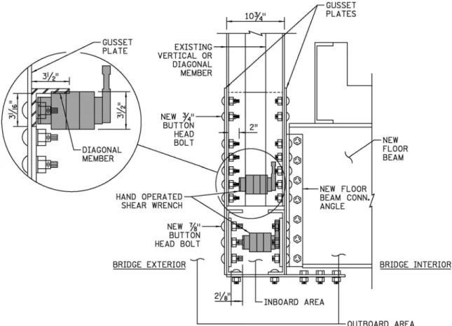
The primary restriction on the use of tension-controlled bolts is the limited space for wrench clearance between gussets or members. In order to overcome this restriction, the use of low-profile wrenches was explored. Figure 16 and Figure 17 show two of the narrowest type of wrenches that are available for areas with tight clearances. For this exercise, the hand operated wrench was evaluated due to its smaller size.
Figure 16: Low Profile Electric Shear Wrench
Figure 17: Low Profile Hand Operated Shear Wrench
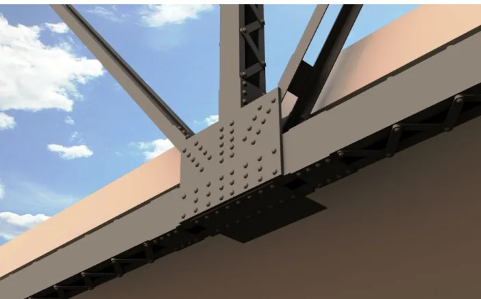
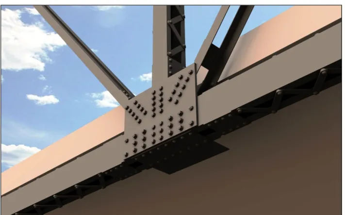
Figure 18 and Figure 19 show two different configurations of button head bolts on a typical gusset plate.
Figure 18 indicates that, with button heads located on the outboard faces of the gusset plate, the low-profile wrench does not fit between the twist off head and the adjacent nut at the inboard area of the bottom chord. Additionally, the wrench body does not clear the leg of truss diagonal members as would be required to fully tension the bolt.
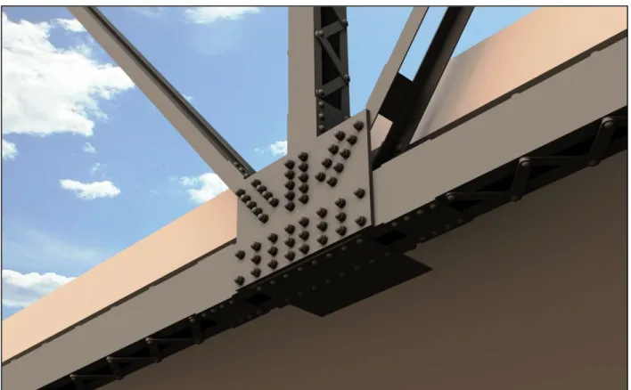
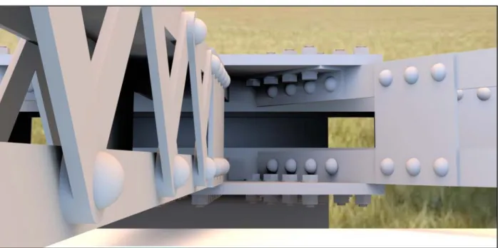
Figure 19 shows that, with the button heads located on the inboard faces of the gussets, wrench clearance would not be an issue. Placing the button heads on the inboard side of the gusset also would offer the benefit of visibility to the public. The bridge will be viewed more often and more closely from the top of the deck rather than the side of the bridge. Figure 20 shows typical views of the gussets from the deck surface.
Figure 19: Gusset Plate Fasteners – Button Head Facing Inboard
Bolt Head Style
Although button head bolts can be used with the button head facing inboard, the hex head nut would still be visible on the bridge exterior. In order to evaluate or mitigate the visual impact of this configuration three options were evaluated. The intent of this evaluation was to determine which option presented the least visual impact to the original look of the rivets as shown in the rendering in Figure 21.
Button Head Bolts with Hex Nuts
This option would utilize button head bolts with the button head facing inboard with a hex head on the outboard side of the gusset. A rendering of this option as seen from below the deck is shown in Figure 22. Figure 23 shows a rendering of this option as seen from the deck, looking over the railing.
Figure 22: Gusset Plate Elevation Rendering – Button Head Bolts with Hex Nuts
Button Head Bolts with Cap over Head Nut
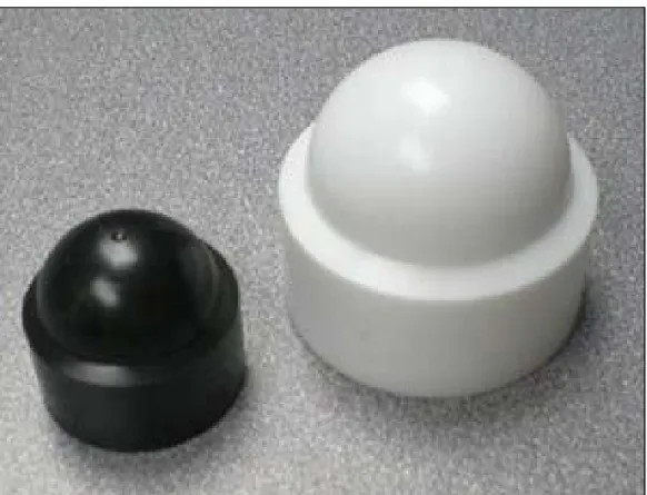
This option would utilize button head bolts with the button head facing inboard with a hex head on the outboard side of the gusset. Commercially available, plastic caps that can cover a hex nut and provide a more rounded look (Figure 24) are available for bolt sizes below ½-inch. While the gusset plate bolts would be larger (3/4-7/8 inch bolts) these caps may be available or may be able to be manufactured for this specific purpose.
A rendering of this option as seen from below the deck is shown in Figure 25. Figure 26 shows a rendering of this option as seen from the deck, looking over the railing.
Figure 25: Gusset Plate Elevation Rendering –Button Head Bolts with Caps over Hex Nut
Hex Head Bolts with Hex Nuts
This option would utilize hex head bolts with a hex head nut on the outboard side of the gusset. While this option would provide the least similar look to the rivets, it would offer the contractor more flexibility by being able to install the bolts from either side of the connection. Figure 27 shows a rendering of this option as seen from the deck, looking over the railing. The view of this connection from below the deck would be identical to that of the button head bolts shown in Figure 22.
Figure 27: Gusset Plate Plan Rendering – Hex Head Bolts with Hex Nut
Recommended Bolt Configuration
The selection of a recommended bolt style should balance the historic nature of the bridge with cost implications and construction feasibility.
Although, the use of hex head bolts would allow installation from both sides of the connection, the contractor is unlikely to prefer this option at gusset locations. The small clearances at the gusset connections make it likely that the contractor would prefer the use of tension control bolts that can be installed from one side of the connection only.
The use of caps over the hex nuts offers the advantage of replicating the shape of the rivets. However, in order to fit over the hex nuts, these caps would be large and would not match the size, scale and depth of the original riveted connections. Additionally, the fact that these caps would likely be made from plastic would not meet the Secretary of the Interior’s Standards for Rehabilitation.
Due to the factors described above, tension-controlled button head bolts are recommended to be utilized at all gusset plate and truss member repairs. On gussets, the bolts are recommended to be oriented with the button head facing inboard. For member repairs, the button head is recommended to be oriented in the direction that is the most visible from the deck surface.
Floor beams, stringers, and lateral bracing members are connected below the deck and are not visible to the public. In order to offer greater flexibility, it is recommended that the style of bolt
used at these locations be left to the contractor’s option. The budget for this project is limited, and the savings gained from this more efficient installation could be applied to other elements of the rehabilitation project.
Since the connections must be replaced and rivets are not allowed, button head and hex head bolts are reasonable substitutions. Using a carefully developed approach for their application, as described above, the use of these fastener types should meet the Secretary of the Interior’s Standards for Rehabilitation.
Table 3 indicates key locations of member repairs and the associated fastener type that are proposed for this rehabilitation.
Table 3: Fastener Location Matrix
Connection Location Rivet BHB HHB CO Comments
Lower Chord Gusset Plates X Heads facing inboard
Lower Chord Repairs X Heads facing inboard
Vertical/Diagonal Member Repairs X Heads facing inboard
Floor Beam & Stringer Connections X Connections are below the deck
Lacing Bars & Batten Plates
(Built Up Replacement Members) X Shop installed
Lateral Bracing Connections X Connections are below the deck
Railing Connections X Original connections used hex head bolts
BHB = Button Head Bolt
HHB = Hex Head Bolt
Truss Members
Truss member deterioration on Bridge No. 3145 can be classified as damage due to traffic impact and section loss due to corrosion.
Truss Member Impact Damage Rehabilitation
Truss members with visible impact damage are identified in Table 4. Impacted members consist of overhead portal bracing and diagonal truss members.
Table 4: Truss Members with Impact Damage Span
No. Truss Location Member Member Type Comments
1 South L2’-U1’ Diagonal The inboard lower angle flange exhibits a 3/4" deformation up to 12" long 1 South L0’-U1’ Portal Brace The lower portal diagonal brace outstanding leg is bent out of plane approximately 1" for a 6" length 2 South L0-U1 Portal Brace The lower portal diagonal brace outstanding angle is bent out of plane approximately 2" for a 2' length 2 South L3’-U2’ Diagonal The entire diagonal is bent out of plane for a 6' length just above the metal railing 2 South L0’-U1’ Portal Brace The lower portal diagonal brace is bent out of plane up to 2" 3 North L0-U1 Portal Brace The lower portal diagonal brace outstanding angle is bent out of plane approximately 3" for a 2' length 4 North L0-U1 Portal Brace The lower portal diagonal brace outstanding angle is bent out of plane up to 3" for a 2'-0" length 4 South L4-U3 Diagonal The entire diagonal member is bent toward the outboard direction approximately 3" 4 South L3-U4 Diagonal The entire diagonal member is bent toward the outboard direction approximately 4" 4 North L0’-U1’ Portal Brace The lower portal diagonal brace is bent out of plane approximately 1/2" for a 3" length
4 South L0’-U1’ Portal Brace Lower diagonal strut has a small kink near bottom connection
The function of the portal bracing members is to keep the primary truss chords aligned and to resist wind loads from the upper portion of the trusses. The function of the diagonal truss members is to support loads through member tension. Figure 28 and
Figure 29 show a typical portal brace and diagonal member with impact damage.
As long as there is no cracking, the extent of this deformation on these members does not significantly reduce the structural capacity of the original diagonal members. However, the sight of bridge members in this state of distress could cause the public unnecessary concern. To minimize this concern, it is recommended that these members be returned to their original, un-impacted, geometry through the use of heat straightening. This repair would follow Standard #6 of the Secretary of the Interior’s Standards for Rehabilitation which states:
Deteriorated historic features will be repaired rather than replaced. Where the severity of deterioration requires replacement of a distinctive feature, the new feature will match the old in design, color, texture, and, where possible, materials. Replacement of missing features will be substantiated by documentary and physical evidence.
Figure 28: Portal Brace Impact Damage – L0-U1, Span 4 North
Truss Member Section Loss Rehabilitation
Members with section loss resulting rating factors below 1.0 are listed in Table 1 and will require repair. Recommended repair details for each deteriorated member are as follows:
L0-L2 North – Span 1
The inside channel of the bottom chord has lost approximately 40% of its steel section adjacent to gusset L1. To reinforce the bottom chord at this area, a reinforcing plate would be installed to span the area of deterioration (Figure 2532). The gusset plate in this area interferes with the proposed reinforcing plate and would require removal. The upper portion of the reinforcing plate would be fabricated to replicate the shape and function of the original gusset.
Figure 30: Member Deterioration: L0-L2 North- Span 1
Figure 32: Proposed Member Repair: L0-L2 North-Span 1
L0-U1 North – Span 1
The inside of member L0-U1 has suffered a significant amount of section loss at the area just above the gusset plate. In order to reinforce this area, a new patch plate would be added to span the deterioration. The patch plate would preferably be installed on the inboard side of the member to minimize visibility. However, the existing batten and lacing plates prevent access to the inboard face of the member at this location. Therefore, it is recommended that the patch plate be installed on the outboard face of the channel (Figure 33).
U3’-L4 North – Span 2
Preliminary analysis shows that this member may have adequate capacity when a lightweight deck system is used. However, the rating is close to 1.0 for this condition and, if final analysis indicates a rating factor below 1.0, this member would require repair.
The proposed repair would cut away a portion of the existing, deteriorated angle. The existing batten plate would remain, but the rivets would be replaced with button-head bolts. A new angle that matches the size of the existing angle will be installed and spliced onto the existing member as shown in Figure 35.
Figure 34: Member Deterioration: U3’-L4 North – Span 2
Figure 35: Proposed Member Repair: U3’-L4 North – Span 2
MEMBER SECTION LOSS GUSSET PLATE BATTEN PLATE EXISTING DIAGONAL MEMBER
L3’-U2’ South – Span 2
This member has suffered impact damage and has cracked at the first rivet on the L3’ gusset. Prior to any repairs, it is recommended that the member be heat straightened to its original geometry. The proposed repair would cut away a portion of the existing, damaged angle. In order to appropriately fit a splice plate within the repair, 3 lacing bars would be cut and removed. A new angle that matches the size of the existing angle would be installed and spliced onto the existing member as shown in Figure 3237.
Figure 36: Member Damage: L3’-U2’ South – Span2
Figure 37: Proposed Member Repair: L3’-U2’ South – Span2
EXISTING DIAGONAL MEMBER CRACK GUSSET PLATE
U4-L3’ South – Span 3
This member has suffered impact damage and has cracked at the first rivet on the L3’ gusset. The proposed repair would cut away a portion of the existing, damaged angle. The two existing batten plates would remain, but the rivets would be removed. A new angle that matches the size of the existing angle would be installed and spliced onto the existing member as shown in Figure 39. Figure 38: Member Damage: U4-L3’ South – Span 3
Figure 39: Proposed Member Repair: U4-L3’ South – Span 3
CRACK GUSSET PLATE EXISTING DIAGONAL MEMBER
L3-L3’ North – Span 5
The channels composing this bottom chord have lost up to 40% of their section throughout the entire length of the member spanning from gusset L3 to L3’. Preliminary analysis shows that this member may only have a capacity of one percent above what is required when a lightweight deck system is used. Any minor amount of future deterioration would result in member capacity less than what is required to support the proposed loading. Given this extensive deterioration, this member is recommended to be replaced.
The recommended replacement member would consist of a shop fabricated member that matches the style and configuration of the original member. Shop installed rivets would be utilized to connect new lacing bars and batten plates to the new channels.
Figure 40: Member Deterioration: L3-L3’ North – Span 5
Gusset Plates
As indicated in the inspection report, the primary gusset plate defects are section loss due to corrosion and pack rust that has built up between plates and main truss members. Addressing the reduced structural capacity due to section loss L0, L2 and L3 gussets and addressing the pack rust at all gussets is recommended.
Pack Rust
Pack rust results when gaps between plates are large enough to allow the infiltration of corrosion reactants (chlorides) while small enough to maintain stagnation of the reactants in the crevice area. With time, these reactants can build up and reduce the pH in the crevice, further increasing the corrosion process. While the gaps can be sealed to prevent the infiltration of further contaminants, the differences in acidity between the outsides and insides of the plates will still allow further corrosion3.
Figure 42: Typical Pack Rust between Gusset and Truss Member
While a number of the lower gusset plates currently have adequate structural capacity, further corrosion would reduce their strength. If the pack rust is allowed to continue, additional gussets and truss members would require replacement in the future. Additionally, the portions of gussets and truss members not visible could be suffering advanced corrosion and section loss in excess of what can be detected by visual inspection.
In order to preserve the existing gusset plates and truss members that currently meet structural capacity requirements and to ensure advanced deterioration has not taken place, it is recommended that all lower gusset plates (which currently meet structural capacity requirements) be removed, cleaned to remove corrosion reactants and reinstalled. The non-visible portions of gussets and truss members are recommended to be inspected for advanced corrosion or section loss. Gussets that have been bent or distorted due to pack rust are recommended to be bent back to their original
shape to minimize the size of crevices. All contact surfaces are recommended to be primed in order to protect the structure from further corrosion.
Gusset L0/L0’ Replacement
Preliminary analysis has indicated that most, if not all L0/L0’ gussets have deteriorated to a point that they no longer can support the proposed loading. All L0/L0’ gussets with rating factors below 1.0 are recommended for replacement under this rehabilitation. The new gussets would be built up to their original configuration in accordance with the original shop drawings using new steel plates, angles and fasteners per Table 3.
Gusset Plates L2 and L3 Repair
While preliminary analysis indicates that the majority of the L2/L2’ and L3/L3’ gussets have rating factors below 1.0, full replacement is not necessarily required. The external, visible portion of the plates can be retained if the inboard splice plate (Figure 44) is replaced as shown in Figure 45. Furthermore, this splice plate could be sized in such a way that further deterioration of the visible portion of the gusset would not automatically be grounds for replacement.
Since the splice plate is not visible and since it could be designed in a manner that would preserve the existing, visible portions of the gussets, it is recommended that all inboard splice plates on gussets L2/L2’ and L3/L3’ be replaced.
Figure 44: Typical Inboard Splice Plate
Interior Gussets
To ensure new bolts do not experience undue stresses during installation, section 2402.3G.2.b of MnDOT’s Standard Specification for Construction states the following:
Ensure the slope of surfaces of bolted parts in contact with the bolt head and nut is no greater than 1:20 with respect to a plane normal to the bolt axis. Assemble bolted parts to fit solidly together. Do not separate bolted parts by gaskets or other interposed compressible material.
A large number of interior gussets have suffered extensive deterioration. While these gussets may have adequate capacity (rating factors greater than 1.0), they will need to be reattached to the existing chord members after they are removed for cleaning, inspection and/or repair. The surface of many gussets has been roughed by corrosion to the extent that the 1:20 slope requirement would not be achievable as shown in Figure 46.
Figure 46: Bolt Installation on Rough Surface
Figure 47 shows typical interior gussets where bolt reinstallation would not meet MnDOT’s surface requirements. Figure 48 shows typical interior gussets where surface requirements would be met. During final design, each interior gusset would be evaluated based on its surface condition. Gussets which do not meet MnDOT’s surface requirements would be replaced, while gussets that meet surface requirements would be retained. All exterior gussets meet surface requirements and would be retained when structural capacity requirements are met. As with the truss members, this approach follows the guidance of Standard #6 of the Secretary of the Interior’s Standards for Rehabilitation.
Figure 47: Gussets with Inadequate Surface Conditions for Bolting
Figure 48: Gussets with Acceptable Surface Conditions for Bolting
Floor System Members
The existing floor system members are composed of 28-inch Bethlehem ‘I’ floor beams located at each panel point and eight 15-inch Bethlehem ‘I’ stringers which span between each floor beam. The purpose of the floor system members is to support the bridge deck.
As indicated in the inspection report, the floor system is in a failed condition. The existing members have suffered corrosion which has led to 25%-100% loss of section on all members and their associated connections. There are numerous locations of holes, corrosion and missing components on all members. In their current condition, the floor members are unable to reliably support a deck section or even their own weight as evidenced by the sagging of some members. The deterioration of these members has progressed to the point where rehabilitation is not possible. Under this rehabilitation, all floor system members will be removed and replaced.
Figure 49: Typical Floor System Member Condition
The selection of replacement members is a balance between the desire to preserve the historic integrity of the bridge while minimizing impacts to the main truss structure. Preliminary structural analysis has shown that a reduction in the weight of the floor system could reduce the number of repairs required due to future deterioration.
In order to reduce the weight of the main floor system, it is recommended that the number of stringers be decreased from 8 to 4. To preserve as much historic integrity as possible, an effort to select stringer and floor beam sizes that closely replicate the original member sections is recommended. Currently, the 15 and 28-inch steel “I” beams used on the original bridge are not produced. 27-inch and 14-inch deep steel beams are the manufactured sizes that most closely match the original floor members and are recommended for this application.
In order to enable continued use of a property under modern conditions and standards, the Secretary of the Interior’s Standards for Rehabilitation allow materials to be replaced when the condition precludes repairs. The proposed approach to the floor beams and stringers will modify
Historic materials by replacing all floor beams and stringers.
Historic configuration by using
− Members of slightly different dimensions and profiles (27-inch floor beams rather than 28 inches as the original; 14-inch stringers rather than 15 inches as the original).
− Fewer stringers (4 rather than 8 historically).
Given the extremely deteriorated condition of the floor beams and stringers, they must be replaced to return the bridge to use, so their replacement can be justified.
Members of the historic dimensions are no longer standard and would have to be custom-made, a costly and time-consuming option, so using members that are readily available today seems reasonable given the relatively small deviation from the historic dimensions and profiles. In addition, these members are beneath the deck and are therefore less visible, if visible at all, to most users of the bridge.
The reduction in stringers will have two benefits: reducing the cost of materials, which will free up funds for other rehabilitation priorities; and reducing the dead load on the trusses. Decreasing the load will help to make possible the replacement of the existing, non-historic timber deck with a historically appropriate concrete deck.
The approach to the floor beams and stringers has considered the larger structural system as well as factors directly related to these members. All in all, the proposed plan complies with the intent of the Secretary of the Interior’s Standards for Rehabilitation.
Lower Lateral Bracing
The function of the lower lateral bracing is to transfer horizontal forces (wind loads) from the main trusses to the substructures. The lower lateral bracing and associated connection plates are severely corroded with areas of 100% section loss. In many areas, the lateral bracing angles have corroded to a point where they have fallen from the structure. In all areas, the lateral bracing connection plates have corroded to a point at which they are unable to transfer forces from the truss into the lateral bracing members. Reuse of the original lower lateral bracing members is not practical from an engineering standpoint and their condition precludes repair. Therefore, replacement is justified under the Secretary of the Interior’s Standards for Rehabilitation.
In order to transfer horizontal loads to the substructures and to preserve historic integrity, the lateral bracing members and connection plates are recommended to be replaced under this rehabilitation. The size of the members and connection plates would be selected to closely match that of the original bracing system.
Figure 50: Lower Lateral Bracing Connection (showing complete section loss)
Bearings
A diagram of the existing bearings is shown in Figure 51. The function of these pinned rocker bearings is to allow the bridge superstructure to rotate freely about the bearing pin. The fixed bearings function is to prohibit movement while the expansion bearings function to allow
movements due to thermal expansion and contraction. The condition of each bearing assembly component is summarized below.
Roller Pin – The roller pin on all bearing assemblies has corroded to the point where rotation has been frozen. The pitting and pack rust on these elements is not providing a smooth surface to allow proper rotation.
Pin Support Plates – The pin support plates of all bearings have been distorted by pack rust and have undergone significant section loss. This loss and distortion have rendered the existing pin support plates unable to allow for proper pin support or pin rotation.
Masonry Plates – The masonry plates and anchor rods for the fixed bearings have undergone extensive corrosion. As evidenced by movement in the fixed bearings, these elements no longer can provide a secure, fixed connection to the piers.
Rollers and Roller Plates – The top and bottom roller plate, as well as the rollers themselves, of the expansion bearings have suffered extensive pitting corrosion. This corrosion does not provide the smooth surface that is required for a roller bearing to function properly.
Figure 52: Typical Condition of Fixed and Expansion Bearing Assembly
Improper bearing function can induce excessive stresses into the main superstructure members. Although the existing bearings are considered historic fabric, reuse is not recommended as improper bearing function could reduce the life of the truss members. Therefore, replacement of all components of each bearing is recommended and would be justified under the Secretary of the Interior’s Standards for Rehabilitation.
Roller assemblies of the type found on the existing bearings require extensive maintenance to function properly. They are very susceptible to dirt, debris and other contaminants and require frequent cleaning and realignment. For these reasons, elastomeric bearing pads are recommended in lieu of roller assemblies as they require almost no maintenance and will provide less resistance to thermal movements over the life of the bridge.
In order to minimize future deterioration and distortion due to pack rust, the replacement bearings will be fabricated from single plates welded together to replicate the shape of the original bearings. Details of the proposed bearings are shown in Figure 53 and Figure 54.
Figure 54: Replacement Expansion Bearing
Railing
Plans for the bridge from 1919-1920 notes that the railing was to be “2 lines of 2-inch I.D. galv. gas pipe” attached by U bolts to 3-inch by 3-inch by 3/8-inch angles. The center of the top pipe was 3-foot-3-inches above the top of the pavement. Based on maintenance records from the 1970s, large sections of railing were damaged by traffic and replaced. The railing was mostly replaced in kind, although the dimension of the replacement pipe varies from 2 inches to 2.5 inches. It seems unlikely that much of the original railing remains. The existing railing has severe corrosion, traffic impact damage, and does not meet current standards for safety.
Since the in-place railing is not original historic fabric and does not provide adequate fall protection, replacement is recommended. The historic design should be the starting point for the design of the new railing, with sensitive modifications to meet current design codes.
Per the applicable design codes, a new railing is required to meet the following requirements:
Table 5: Combination Bike/Pedestrian Railing Design Requirements
Feature Requirement Applicable Code Reference
Height 4’-6” above walking surface MnDOT Bikeway Facility Design
Manual – Section 6-3.2 MnDOT LRFD Bridge Design Manual – Sect. 2.4.1.2 & 13.2.2 Max. Opening 6”/4” (above/below 27”) between
horizontal components MnDOT Bikeway Facility Design Manual – Section 6-3.2 MnDOT LRFD – Section 13.2.2
Handrail Handrail at 2’-8” above the top of deck MnDOT LRFD Bridge Design
Manual – Section 2.4.1.2 Design Loading 50 pounds/ft. (horizontally & vertically)
+200 pounds (any direction) at the top of the railing
In addition to the above requirements, NCHRP 20-7 (168) Determination of Appropriate Railing Heights for Bicyclists states that the “top railing of a bicycle railing should be rigid. A steel mesh or tension cable system that replaces the intermediate rails may be considered to allow a more transparent look.”
For the recommended replacement railing section, the vertical spacing of the 2-inch pipe elements would be scaled up to match the proportions of the original railing with the lower pipe element acting as a handrail at the required 2-feet-8-inches above the walking surface. The pipe elements would be attached to vertical posts using 5/8-inch U-bolts in accordance with the original design. Like the original railing, the vertical posts would be located such that there are three posts equally spaced between each panel point. The posts would be fabricated with steel angles whose size and spacing will generally conform to that of the original 3-inch angles while providing sufficient strength to meet current design loadings. A comparison between the original and the proposed railing cross-section is shown in Figure 55.
In order to meet MnDOT maximum spacing requirements, 1/4-inch stainless steel cables would be placed between the main horizontal pipe elements. Per the Post-Tensioning Institute’s Design of Prestressed Barrier Cable Systems, the cable spacing should be reduced from code requirements to overcome any cable sag. Therefore, the cables would be spaced at 3-inches and 5-inches for the lower and upper portions of the rail, respectively. To provide anchorage for the cables, the typical post angle would be replaced with a larger anchorage post at the end of each span. A visual rendering of the original railing compared to the recommended railing is shown in Figure 56 and Figure 57.
Figure 56: Photo of Existing Railing
Abutment Piers
The primary function of the abutment piers is to support the vertical and horizontal loads of the trusses. A secondary function of the abutments is to retain the approach fill that supports the pathway.
Abutment Pier 1
The backwall and endwalls of Abutment Pier 1 have been replaced. The backwall has undergone significant movement, has severely cracked and is no longer functioning as intended to retain the approach path. The endwalls have become detached from the abutment and are no longer serving their original, intended purpose.
Under the proposed rehabilitation, reconstruction of the backwall and endwalls (non-historic) is recommended. In order to preserve historic fabric, retaining the remainder of the abutment is recommended.
Figure 58: Abutment Pier 1 – Proposed Rehabilitation
Abutment Pier 6
The thickness of the backwall has been reduced by 20%-50% due to concrete spalling and delamination. The concrete has deteriorated to a point that a steel plate was installed to replace portions of the concrete. A small concrete wall was added to retain the embankment on the north side of the bridge. This wall was not installed as part of the original construction.
The purpose of the backwall is to retain the approach path. The backwall concrete has deteriorated to an extent that repair is not structurally practical. Any permanent support would require anchorage into the existing concrete. However, the existing concrete has deteriorated to a point that a reliable anchorage could not be obtained. Replacement of the existing backwall is recommended as part of this rehabilitation. The steel plates installed as a backwall repair are not considered historic fabric and are recommended for removal.
The southern endwall concrete has deteriorated to a point where reliable anchorage to the existing abutment is not practical. Any attempt to drill in new reinforcement would likely destroy the in-place concrete. The northern endwall concrete is sound and anchored to the existing abutment
body. Under the proposed rehabilitation, the southern endwall is recommended to be reconstructed while the retaining the northern endwall is recommended.
The north concrete retaining wall is no longer functioning to retain the embankment and does not contribute to the historic integrity of the structure. Under the proposed rehabilitation removal of this wall and a subsequent regrading of the slope is recommended.
Figure 59: Abutment Pier 6 – Proposed Rehabilitation
Piers 2-5
A diagram of a typical lake pier is shown in Figure 60. The purpose of the pier concrete is to support the superstructure and to protect embedded steel reinforcement from corrosion. Vertical loads (structure weight, pedestrian loads, etc.) are transferred from the bearings to the pier caps and into the pier columns. Wind and other horizontal loads are transferred from the bearings to the anchor rods and into the pier caps. The stem wall transfers load to each column and contributes to the stability of the pier columns.
Figure 60: Typical Pier Components
The original pier concrete has suffered a large amount of deterioration due to freeze-thaw cycles. Water has accessed the pier cap and stem wall concrete through leaking superstructure expansion joints. The pier columns are also permanently exposed to the varying lake water levels. Figure 61 through Figure 63 show the typical level of deterioration that Piers 2-5 have undergone.
Figure 62: Typical Freeze-Thaw Deterioration at the Pier Cap
Figure 63: General Pier Deterioration (Pier 4)
Since the priority is to preserve historic fabric, pier repair was given preference over pier replacement. An exercise was conducted to determine the extent and the practicality of all required
repairs. In order to provide reliable support to the bridge superstructure, the following was assumed to be a minimum level of repair for each component:
Cap – The pier cap concrete at all pier locations has deteriorated, spalled and cracked. The caps have lost the ability to reliably support horizontal loads from anchor rods.
The cap concrete is required to be of a quality that will be able to properly resist vertical and horizontal loads from the bearing and the associated anchor rods. The quality of the concrete has deteriorated to a point where reliable anchorage cannot be achieved. The caps would require complete replacement in order to function as intended.
Stem Wall – On all piers, approximately 1-foot of stem wall concrete has deteriorated at the top of the wall. The bottom 3-4 feet of the stem wall concrete has either suffered deterioration or has completely spalled away. The center portion of the stem wall has miscellaneous areas of deterioration, spalling or cracking.
The stem walls are required to provide support and stability through the concrete and the embedded steel reinforcement. Reliable column stability cannot be achieved with the current condition of the upper and lower portions of the stem walls. Repair of the stem wall would require replacement of the upper 1 foot and the lower 3-4 feet of the stem wall. Supplemental rebar would be added to replace the existing corroded reinforcement. Additionally, in order to protect the embedded reinforcement, miscellaneous spalls and delaminations would require patching.
Columns – On all piers, the column concrete has deteriorated approximately 3-4 feet above the water line. Concrete in this area has spalled from 6-14 inches and the remaining concrete has deteriorated for an undetermined depth. The column reinforcement at the water line has corroded to a point where it is incapable of providing any structural resistance. Although, only the portion of the piers above water are visible, it is reasonable to assume that a same or greater level of deterioration has occurred below the water line to a depth where freezing occurs (typically 4-5 feet in Minnesota). Additionally, the remaining portions of pier columns have miscellaneous areas of deterioration, spalling and cracking throughout.
The repair of the columns would require patching of the concrete that has spalled away and the addition of supplemental rebar to replace the corroded reinforcement. In order to achieve a sound patch, existing concrete that has suffered freeze-thaw damage would require removal. While the exact depth of deteriorated concrete is not known, a reasonable assumption would be in the range of 6-12 inches. For this exercise, an average concrete removal depth (including the 6-14 inch spalls) was assumed to be 18 inches. The height of this repair was assumed to be 4 feet above and below the water line. Additionally, the portions of concrete between the cap and 4 feet above the water line are spalling, cracking and are generally deteriorated. In order to adequately patch these areas, approximately 6 inches of concrete was assumed to be removed and replaced.
Figure 64: Typical Pier Repair Elevation
Figure 65 is a visual rendering of what the pier would look like during construction assuming the minimum level of repairs defined above. The upper portion of the pier columns and stem wall would be supported by a small column of unreinforced concrete. The only portion of visible, original concrete that would remain (at a maximum) is a 5-6 foot tall portion of the stem wall. The remaining, original concrete would be encased in new concrete.