Data Locality in Parallel Rendering
Frederik W. Jansen1Erik Reinhard2 1
Faculty of Information Technology and Systems, Delft University of Technology, The Netherlands
2
Department of Computer Science, University of Bristol, United Kingdom
Abstract. One of the main challenges in global illumination is rendering scenes with millions of polygons and megabytes of textures. Combining the processing power and the memory of multiple processors or workstations to render these complex scenes is an attractive proposition but the complex interactions between data and processing introduces a significant amount of data communication. Data locality methods may improve cache coherence and cache access coherence by finding an optimal data partitioning, by re-ordering computations, and by replac-ing complex geometry with simplified image-based representations. We review the different data locality methods and focus on local caching of global radiance values. We present the results of an implementation in the ray tracing program Radiance.
1
Introduction
Parallel rendering has long been considered an answer to the high computational de-mands of global illumination algorithms such as ray tracing and radiosity, and the ever increasing size of models has recently spurred a renewed interest in this subject. The complexity of computer models has increased tremendously over the years due to im-proved data sampling and more powerful modelling techniques. Scenes with several millions of polygons and many megabytes of texture images are no exception anymore. Besides model data, most algorithms also employ additional data structures such as ra-diosity meshes, spatial subdivision structures, mipmaps, and other methods to increase the efficiency and quality of the sampling. These temporary data structures may also take many megabytes. Given the total memory requirements of several gigabytes, dis-tributing data in addition to disdis-tributing processing, may well prove to be a necessity in such demanding applications.
Distributing the processing and the data over multiple processors, however, cre-ates an overhead in the form of communication needed to match processing and data. Either tasks are migrated to processors that store the necessary data (data parallel ap-proach) or tasks are distributed and data is communicated on request (demand-driven approach). The data parallel approach is scalable with respect to problem size and can render arbitrarily large models, but it is difficult to spread the processing evenly over the processors, due to ’hot spots’ in the scene, such as light sources, and due to the uneven distribution of processing over time. Dynamic adaption of the data distribution over the processors is complex and introduces extra overhead.
1E-mail: [email protected] 2E-mail: [email protected]
The demand-driven approach achieves a better load balance but the efficiency of this approach is very much dependent on the amount of coherence that can be found in subsequent data requests. Assuming that data retrieved from other processors is cached locally, in highly complex scenes coherence between subsequent data request will be low and therefore caching is of less use. Hybrid approaches try to combine data-parallel and demand-driven scheduling in such a way that non-coherent data tasks are scheduled data parallel and data coherent tasks are scheduled demand-driven [32, 14, 25]. The demand-driven tasks then compensate for workload variations in the data parallel task distribution. However, when the scene is complex and the amount of available data coherence is low, the hybrid scheduling suffers a loss of suitable demand-driven tasks and falls back to the (in-)efficiency of the data-parallel approach.
It turns out that for both the demand-driven approach and the data parallel ap-proach, the efficiency is very much dependent on the amount of data locality that can be achieved. When it is not possible to partition the data and tasks such that requests for remote data are minimal, then additional methods are needed to reduce data or task communication, for instance by locally representing remote data in a compact format or by caching intermediate results. In this paper we will review some of these methods and discuss their application to parallel rendering. We will do this in the context of a ray tracing algorithm using diffuse sampling, such as described in [39], but the methods are applicable to other ray tracing and radiosity algorithms as well. Data locality tech-niques are also useful in single processor configurations to reduce the amount of data transfers between the different levels of caches, memories and discs [23].
The paper is structured as follows. We first discuss several methods to improve data locality such as data partitioning, access coherence, impostor techniques and (ir-)radiance caching (section 2). Then we present some experiments with incoming radi-ance caching (section 3) and draw some conclusions (section 4).
2
Data Locality
Data locality is a measure of how well data can be selected, retrieved, compactly stored, and re-used for subsequent processing tasks. Finding a good partitioning to distribute data is a first step to successfully associate data with specific tasks. A next step is to optimise access coherence, i.e. to find an optimal ordering of the computations to min-imise the number of times data items will have to be re-communicated or re-read from disc. Alternatively, data can be compressed or replaced by a more compact representa-tion, in particular for remote objects and environments, when an exact representation is not required.
2.1 Data Partitioning
When data has to be distributed, a first issue is how scene data should be divided over the processors. Initial data distributions can have a strong impact on how well the sys-tem performs. The more evenly the workload associated with the data is distributed, the less idle time is to be expected. In order to be able to distribute a part of the scene, for instance a cell of an octree spatial subdivision, first the expected cost per voxel should be computed. In a second step, the voxels can be distributed across the processors,
pre-serving data locality as much as possible, while at the same time attempting to equalise the cost per processor.
Some initial research has proved that it is possible to estimate the cost of a single ray traversing an octree structure [17, 36, 27]. The number of intersection tests for each node in the octree can be estimated by averaging the depth of the leaf cells of the octree, weighting these depths by the surface area of the cells, and computing the probability that a ray traversing that voxel intersects one of the objects contained within the voxel. Alternatively, the cost per voxel could be predicted by estimating the number of rays that would traverse each voxel during rendering [26]. Such an algorithm would take into account the distribution of objects over the scene, as well as the view point and the position of light sources. The data distribution would therefore be tailored to the particular view point chosen.
Given an initial load estimation, a data distribution may be devised such that as much object coherence as possible is retained. A possible algorithm to distribute octree branches over processors may use the cost per voxel information to split off separate branches. The nearer to the root of the tree this split occurs, the more coherence be-tween sub-parts of the scene is preserved. However, it should be noted that preserving coherence and equalising the estimated workload per processor are conflicting goals.
A different and slightly more complicated algorithm is called region growing [38], where each processor receives a seed voxel. At each subsequent step, a voxel adjacent to one of these seed voxels is assigned to the same processor. The estimated workload is distributed evenly by adding the adjacent voxel with the highest cost function to the processor with the lowest accumulated cost function. This process is continued until all voxels are assigned to a processor.
Octrees and grids are axis-aligned subdivisions that do not always segment a model in an optimal way. More data coherence may be obtained with a space partitioning that is aligned with the internal structure of the model. The BSP-tree method uses planar surfaces of the model to derive a binary space partition. Several strategies have been developed to choose the most suitable faces as primary dividing planes and to optimise the data coherence within the resulting space partitions (preferably cubic and not long and thin) while keeping the number of split surfaces as low as possible [5, 21, 37]. In [20] a clustering algorithm is applied to the surfaces in a building environment to align the partitioning with the structure of the floor plan.
A very fruitful approach is to partition the scene on the basis of inter-visibility [37]. Energy transfer can only take place between surfaces that are mutual visible. A visibil-ity preprocessing can be used to create local clusters and to calculate visibilvisibil-ity between these clusters. This information can be stored in a visibility graph with the clusters as nodes. The importance of energy transfer between surfaces can be taken into account such that two surfaces with a high ‘form-factor’ interaction are likely to end up in the same cluster [6].
2.2 Access Coherence
Cache coherence may be improved by re-ordering computations, e.g. by temporarily suppressing computations that need data which is locally not available, or by grouping tasks that share similar data needs. Deviating from the sequential order will always
introduce some extra storage of state information. This is not uncommon in parallel implementations where tasks are migrated or tasks are temporarily suspended waiting for data to arrive. Re-ordering may be accomplished for instance by grouping shadow rays or by performing ray tracing in breadth-first order [12]. Grouping primary rays together allows an efficient selection of data and guarantees a high cache access coher-ence [24, 33]. In fact, any multi-pass or pre-processing may be viewed as a re-ordering of computation (compared to a full MC ray tracing algorithm). A separate light pass may significantly increase ray coherence at the cost of the storage of a photon map or radiance cache.
Finding an optimal traversal in the visibility graph to minimise the number of cluster swappings during one interaction of a progressive radiosity pass can be approached as a travelling salesman problem [19]. An other scheduling strategy is to use the voxels of a spatial subdivision as a ‘scheduling grid’ [23, 22]. In this approach, rays are processed in voxel order. A voxel with object data is only loaded (or created) when enough work is available or when its contribution to the final rendering wins over processing other data voxels. The advantage is that rays that pass through the same voxel are processed together, even if their origin or descend is different.
Beside the cost for storing extra state information, there may be a penalty involved for not taking the optimal order of computations. For instance, deferring some shooting tasks in progressive radiosity may lead to a slower convergence [6].
2.3 Impostor Techniques
Even with a suitable data partitioning and coherent cache access, interaction between data partitions may not be completely avoided, leading to either data or task commu-nication. The amount of data communication can be reduced by replacing the remote data with some local ‘placeholder’. This may be a simplified representation or an image ‘impostor’ of the real data. One of the first applications of this idea was the introduc-tion of so-called ‘virtual walls’, separating planes between partiintroduc-tions placed at strategic places (e.g. portals) to serve as interface between two partitions [41, 2]. A drawback is that when only radiosity is transferred through the virtual walls, directional information will be lost.
Virtual interfaces [1, 29] borrow the data partitioning from the virtual walls tech-nique but are an improvement in that directional information is maintained. Each source patch first shoots its energy into its own environment. Then it is passed to the neighbour-ing partitions together with a visibility (or shadow) mask. This mask is a discretisation of the hemisphere around the source patch. The directions that are blocked by objects in the processed environments are disabled. The data transferred to the neighbouring partitions is thus exact in position and size but is approximate in the discretisation of the directions left open after blocking of the light by intermediate geometry. A similar technique using the convolution of a blocking mask and an incoming light source to project shadows onto surfaces is proposed in [35].
Environment mapping [3, 10] is an other variant on the virtual walls technique. Each partition or object cluster is surrounded by an environment map to represent the incoming intensity from the rest of the scene. Instead of fetching data from remote pro-cessors, or migrating tasks to other propro-cessors, a simple table lookup is enough to find
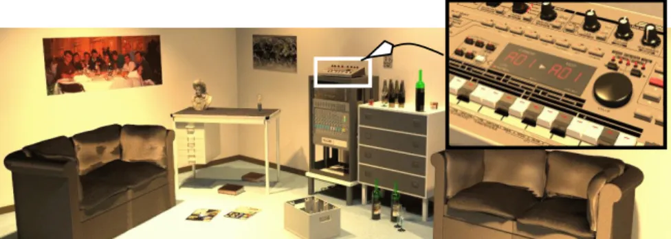
Fig. 1 Clusters of small objects, such as the synthesiser enlarged in the inset, may be fetched at a lower resolution for the chosen viewpoint.
an approximate shading value which would otherwise be very costly to compute [28]. As the environment map is created from only one arbitrary view point within the parti-tion and used for any ray origin in this partiparti-tion, it will introduce errors which show up in the form of displaced reflections. When used solely for diffuse interreflection, this may however not prove to be much of a problem. The accuracy can be controlled by in-creasing the radius of the environment map with respect to the size of the local partition. Geometric simplification is another successful strategy. The basic idea is that if a complex object or a densely populated part of the scene is at some distance, then without sacrificing accuracy, the complex geometry can be replaced with a simplified geometry carrying the same energy and having similar reflection and emission properties.
An example where the full resolution of geometry data is not always required is given in figure 1. Assuming that the objects are distributed across a number of proces-sors, the processors responsible for the area where the viewpoint is, may occasionally need to access data that is far away. The knobs on the equipment at the back of the room could be fetched at a far lower resolution without affecting the quality of the sampling. There are many different ways in which geometry can be simplified or stored at different resolutions. The methods that should be considered are ones where geometry is replaced with simpler geometry and techniques where geometry is replaced with shading information (impostors, grouping of patches).
Geometric simplification algorithms attempt to reduce the polygon count of objects by replacing large groups of small surfaces by a small group of larger surfaces [13, 8]. Such algorithms usually do not replace different surface reflectance properties by an average BRDF. However, preserving average material properties is important for geometric simplification algorithms to be useful in realistic rendering algorithms.
This issue was addressed by some of the grouping and clustering techniques devel-oped for hierarchical rendering. A locally dense occupation of small polygons, e.g. a plant, can be replaced by an enclosing volume that inherits the same global shape, re-flection, emission, absorption or transparency properties as the original. Several meth-ods have been developed differing in the way they represent these properties, either as shading transfer [15], transmission transfer [34] or reflection distribution [31]. Most
of these techniques where originally developed to improve the sampling quality, as the intersection of a complex object is not only expensive but also prone to aliasing.
Textures can be used to replace detail geometry, e.g. to represent ornamental dec-orations on a fac¸ade. If the geometry is simplified to a single polygon or box and the texture represents the complete geometry then we talk about image impostors [7, 18]. Image impostors work in much the same way as environment maps, the difference be-ing that rather than replacbe-ing the surroundbe-ings of an object with a box plus texture map, the object itself is replaced with a simple cube plus texture map. Therefore, impostors borrow from environment mapping in construction and from geometric simplification in usage.
Image-based rendering techniques may also be viewed as impostor techniques, as they can represent the incoming radiance from a scene for a certain region of view points and directions. However, the storage costs of these techniques are still prohibitive.
2.4 Irradiance Caching
The disadvantage with impostor techniques is that they all require a pre-processing stage, and sometimes even require user intervention, which makes them slightly awk-ward to use. A possible method to overcome this, is to build a data structure on the fly. For instance, when a processor holds part of the scene and for reflection calculations has to sample its environment, then either ray tasks are submitted to other processors or remote data is requested, but in both cases the query is expensive. Storing the results of these queries allows us to re-use this information for rays in similar directions. Thus for subsequent rays the data structure is queried. If there is sufficient information present in the data structure, this is used (as in environment mapping). If not, the ray task is executed as before and when a shading result is returned, it is used for both shading the ray and updating the data structure. The further the computation proceeds, the less com-munication between processors will be necessary, as processors will build up an image of what surrounds them. We term such methods “directional irradiance caching” [9]. The following section describes an implementation of this technique for the Radiance program.
A suitable data structure to store such incoming radiance values is a 5D tree, adap-tively subdivided both on position and direction. Each node is subdivided when the number of averaged radiance values exceeds a certain threshold. Such a tree struc-ture has been used to predict important sampling directions and therefore minimises the amount of time spent on directions that do not substantially contribute to the final shading [16].
Instead of storing the incoming radiance (or field radiance function), also the re-sulting irradiance values for all directions could be stored. Irradiance at a point on a surface is the cosine-weighted integration of the incoming radiance over all directions of the hemisphere. In case of diffuse reflection the radiance at that point is then easily computed by multiplying the irradiance with=. The irradiance distribution function is much smoother than the radiance distribution function and can be more compactly represented [11]. However, it requires a preprocessing as it is more complex to adap-tively built this representation (unless all incoming radiance values are stored as well).
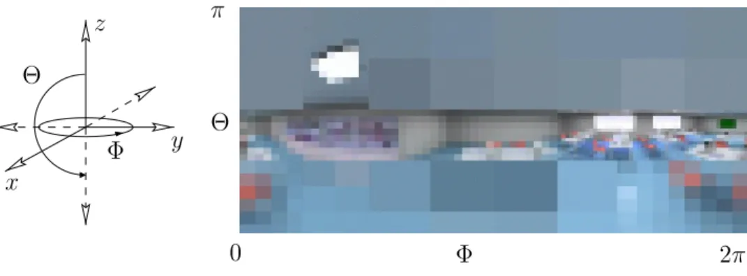
0 2 y z x
Fig. 2 The surroundings of a voxel are discretised into a full sphere using a quadtree. The right image shows what a fully developed cache may look like for the voxel shown in figure 3.
spect to compact representation of incoming radiance values from different directions and for a specified region of view points.
3
Directional Irradiance Caching
In this section we describe some experiments with an implementation of a directional irradiance cache within the Radiance lighting simulation package [39].
3.1 Radiance
The ray tracing method employed in the Radiance package is an extended form of ray tracing which also samples the diffuse interreflection in a scene. This diffuse reflection at a point is calculated by constructing a hemisphere over the point and sampling a large number of directions over this hemisphere. The number of rays to accurately sample the diffuse interreflection can be very high. To reduce the number of rays Radiance uses two methods, an adaptive sampling method to concentrate the sampling effort in directions with a high variance, and a radiance cache to store irradiance values com-puted earlier [40]. When a new intersection is found and if sufficient irradiance values are stored in its vicinity, instead of sampling the diffuse reflection, a new irradiance estimate is obtained by interpolating some of the cached irradiance values. The validity of this principle is based on the fact that diffuse reflection tends to vary slowly over a surface. Moreover, the error introduced by the interpolation can be kept within bounds by specifying a maximum radius in which the cached value is valid.
The directional (incoming) radiance cache method that we propose can be used in conjunction with the above interpolation method. Instead of storing the end result of the hemisphere sampling, it stores the incoming radiance values as sampled by the diffuse rays.
3.2 Directional Cache
In our implementation we associate one cache with each leaf node of an octree spatial subdivision. The directional cache is created on the fly and is adaptively subdivided in latitudinal and longitudinal directions, resulting in a quadtree tree structure (figure 2). Each node of the tree represents a solid angle and stores an average intensity, the num-ber of rays (samples), and a variance value. Each leaf node is subdivided whenever its ‘samples’ value equals a specified minimal number. This way, we ensure that the average intensity stored in a leaf node is mainly composed of intensity values obtained by rays traced within the leaf node’s own solid angle1. When the solid angle covered
by a node is small enough, the node steps into a second stage. In this stage leaf nodes in the tree are subdivided using variance as a criterion. The reliability of the stored variance depends on the number of samples from which it was calculated. For this rea-son, a leaf node is subdivided only when it contains enough samples and the variance between these samples is considered high. Node subdivision is constrained by a maxi-mum depth. When a given cache partition is sufficiently sampled, no further sampling in that direction will be done, and the cache values can be re-used for subsequent rays that are sampled in that direction.
However, just like the environment map, we do not use the cache for rays that find an intersection within a specified radius from the centre of the node. As the rays’ origins may be distributed over the cell, the cache will not give an accurate prediction for rays that find an intersection nearby. The cache therefore is only used to represent the environment at a certain distance of the node. Local geometry - which in general will have a significant impact - is always sampled accurately.
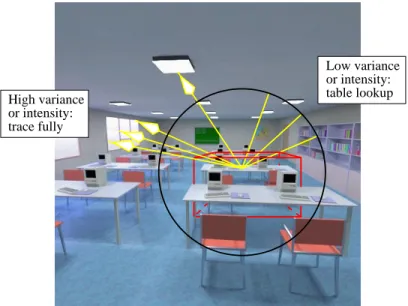
Tracing diffuse rays is thus performed in stages. Each ray is traced locally, until ei-ther an intersection is found, or the ray leaves the local neighbourhood (see figure 3). If the ray is not considered to be local anymore, the directional cache is read to determine whether the information in the cache is accurate enough for the ray’s direction. If this is the case, the directional cache provides an estimate for the shading result of the ray. Otherwise, the ray needs to be traced.
Controlling the size of the radius with respect to the size of the voxel provides a convenient way of trading accuracy for speed.
3.3 Implementation and Results
In order to measure the effectiveness of the directional cache, the cache was imple-mented in the Radiance program and used in combination with Radiance’s own radi-ance cache. Several tests were performed using different quality settings, in line with values recommended for Radiance. A high quality setting was chosen to serve as a reference. The scene used to evaluate the directional cache with these settings, is the well-known conference room, as depicted in figure 4. All images were rendered at a resolution of512x512, and filtered to a resolution of256x256.
Table 1 shows the reduction in number of intersection tests (performance) and ren-dering time, obtained with the directional cache. A mean squared error (MSE) was 1Upon subdivision, only the average intensity of the parent node is copied, the ‘samples’ value is set to
or intensity: table lookup or intensity: trace fully High variance Low variance
Fig. 3 When reaching the perimeter of locality without intersecting an object, only in important directions the sampling is continued. The remainder of the rays are estimated by reading the cache.
Quality Radiance Directional Cache Intersection Tests Time Intersection Tests Time Gain
Accurate 257,103,496 16.6 222,453,281 14.2 13.5% 14.8%
Fast 119,065,157 5.4 115,040,115 5.1 3.4% 5.8%
Low 106,789,984 4.4 104,533,101 4.3 2.1% 3.8%
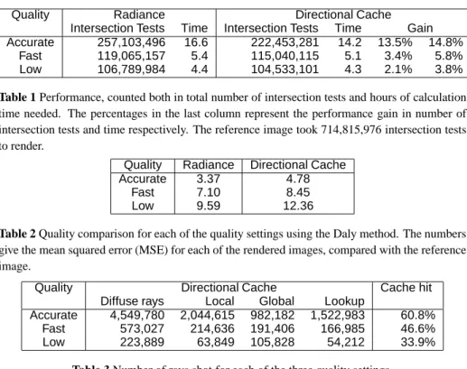
Table 1 Performance, counted both in total number of intersection tests and hours of calculation time needed. The percentages in the last column represent the performance gain in number of intersection tests and time respectively. The reference image took 714,815,976 intersection tests to render.
Quality Radiance Directional Cache
Accurate 3.37 4.78
Fast 7.10 8.45
Low 9.59 12.36
Table 2 Quality comparison for each of the quality settings using the Daly method. The numbers give the mean squared error (MSE) for each of the rendered images, compared with the reference image.
Quality Directional Cache Cache hit
Diffuse rays Local Global Lookup
Accurate 4,549,780 2,044,615 982,182 1,522,983 60.8%
Fast 573,027 214,636 191,406 166,985 46.6%
Low 223,889 63,849 105,828 54,212 33.9%
Table 3 Number of rays shot for each of the three quality settings.
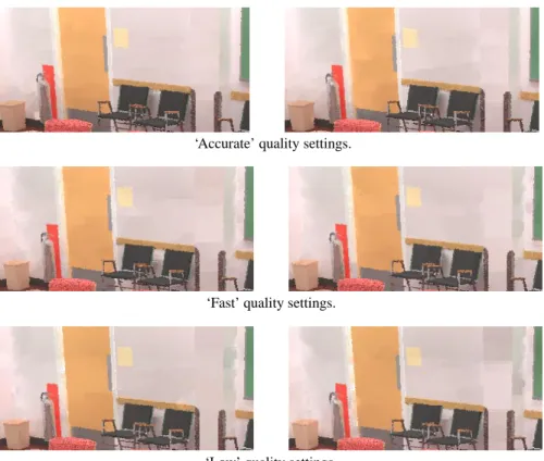
computed based on the perceptional Daly model [4, 30], to give an indication of how the images perceptually differ from the reference image. Table 2 shows the results of this quality comparison, and figure 5 shows the actual Radiance and Directional Cache images. Table 3 gives the total number of diffuse rays traced for the conference room model. This number is subsequently split into a component which counts the number of rays that intersect with a nearby object, the number of rays that are traced outside the local perimeter (because the cache was not sufficiently filled for that direction) and the number of rays that could be approximated by a cache lookup.
The cache hit ratio is defined as the number of cache lookups over the number of rays that reached the perimeter (global plus lookup). As can be seen, the cache gives a reduction of up to 60% in the number of global rays, which for a parallel implemen-tation would greatly reduce the communication costs. The MSE figures show that the directional cache looses some of the accuracy obtained with standard Radiance. Vi-sual artifacts, however, are hardly noticeable, which may be partly due to the linear interpolation of Radiance’s own cache.
Beside the reduction in global rays, the method has several other advantages. Like the environment mapping algorithm, the cache builds a ‘filtered’ representation of the environment and reduces the over-sampling of far-away areas that do not contribute that much. Moreover, the reduction in global rays is for the bigger part realised towards the end of the rendering process, which is advantageous in parallel rendering, because non-local rays cause long termination delays [25].
‘Accurate’ quality settings.
‘Fast’ quality settings.
‘Low’ quality settings.
Fig. 5 Detail of images rendered using standard Radiance (left) and the Directional Cache (right).
4
Conclusion
Model complexity has become a primary motivation to use distributed processing. But to achieve some efficiency and scalability we need data locality methods that optimally partition the data and that compactly represent remote data. In the context of rendering, this often means conversion of geometry and lighting into radiance information. In this paper we have given an overview of data locality methods for parallel rendering and we have focused on a directional cache to store and re-use incoming radiance values. We have presented the results of an implementation in the program Radiance. Although the number of non-local rays is drastically reduced, the overall effect on the cache efficiency and the data communication in a parallel implementation still has to be assessed.
Acknowledgements
All images were rendered using the Radiance lighting simulation package [39]. The authors would like to thank Greg Ward Larson for putting his programme and the con-ference room model in the public domain. Thanks to Arjan Kok for allowing us to use the results of his modelling efforts. Rick Germs did the implementation and the
testing of the irradiance cache. We also thank Alan Chalmers for providing useful com-ments. This work was funded in part by the EC under TMR grant number ERBFM-BICT960655.
References
1. B. Arnaldi, T. Priol, L. Renambot, and X. Pueyo. Visibility masks for solving com-plex radiosity computations on multiprocessors. Parallel Computing, 23(7):887– 897, jul 1997. Special Issue on Parallel Graphics and Visualisation.
2. B. Arnaldi, X. Pueyo, and J. Vilaplana. On the division of environments by virtual walls for radiosity computation. In Photorealism in Computer Graphics, pages 198–205, 1991. Proceedings 2nd EG Rendering Workshop.
3. J. F. Blinn and M. E. Newell. Texture and reflection in computer generated images.
Communications of the ACM, 19(10):542–547, October 1976.
4. S. Daly. The visible difference predictor: an algorithm for the assessment of image fidelity. In A. B. Watson, editor, Digital Images and Human Vision, pages 179–206. MIT Press, 1993.
5. H. Fuchs, Z. M. Kedem, and B. F. Naylor. On visible surface generation by a priori tree structures. In ACM Computer Graphics, volume 14, pages 124–133, July 1980. 6. T. A. Funkhouser. Coarse-grained parallelism for hierarchical radiosity using group iterative methods. In H. Rushmeier, editor, SIGGRAPH 96 Conference
Proceed-ings, Annual Conference Series, pages 343–352. ACM SIGGRAPH, Addison
Wes-ley, August 1996. held in New Orleans, Louisiana.
7. T. A. Funkhouser and C. H. S´equin. Adaptive display algorithm for interactive frame rates during visualization of complex virtual environments. In J. T. Kajiya, editor, Computer Graphics (SIGGRAPH ’93 Proceedings), volume 27, pages 247– 254, August 1993.
8. M. Garland and P. S. Heckbert. Surface simplification using quadric error metrics. In T. Whitted, editor, SIGGRAPH 97 Conference Proceedings, pages 209–216. ACM SIGGRAPH, Addison Wesley, August 1997.
9. R. Germs, E. Reinhard, and F. W. Jansen. Directional irradiance caching. Submitted for publication, 1998.
10. N. Greene. Environment mapping and other applications of world projections.
IEEE Computer Graphics and Applications, pages 21–29, November 1986.
11. G. Greger, P. Shirley, P. M. Hubbard, and D. P. Greenberg. The irradiance volume.
IEEE Computer Graphics and Applications, 20(2):32–43, 1997.
12. P. Hanrahan. Using caching and breadth first search to speed up ray tracing. In
Proceedings Graphics Interface ’86, pages 55–61, Toronto, 1986. Canadian
13. H. Hoppe, T. DeRose, T. Duchamp, J. McDonald, and W. Stuetzle. Mesh optimiza-tion. In J. T. Kajiya, editor, Computer Graphics (SIGGRAPH ’93 Proceedings), volume 27, pages 19–26, August 1993.
14. F. W. Jansen and A. Chalmers. Realism in real time? In M. F. Cohen, C. Puech, and F. Sillion, editors, 4th EG Workshop on Rendering, pages 27–46. Eurographics, jun 1993. held in Paris, France, 14–16 June 1993.
15. A. J. F. Kok. Grouping of patches in progressive radiosity. In M. Cohen, C. Puech, and F. Sillion, editors, Fourth Eurographics Workshop on Rendering, pages 221– 231, Paris, France, jun 1993.
16. E. P. Lafortune and Y. D. Willems. A 5D tree to reduce the variance of monte carlo ray tracing. In P. M. Hanrahan and W. Purgathofer, editors, Rendering Techniques
’95, pages 11–20. Eurographics, Springer Wien, June 1995.
17. J. D. MacDonald and K. S. Booth. Heuristics for ray tracing using space subdivi-sion. The Visual Computer, (6):153–166, 1990.
18. P. W. C. Maciel and P. Shirley. Visual navigation of large environments using textured clusters. In P. Hanrahan and J. Winget, editors, 1995 Symposium on
Inter-active 3D Graphics, pages 95–102. ACM SIGGRAPH, April 1995.
19. D. Meneveaux and K. Bouatouch. Memory management schemes for radiosity computation in complex environments. Technical report, INRIA, 1997. To appear in Computer Graphics International, 1998.
20. D. Meneveaux, E. Maisel, and K. Bouatouch. A new partitioning method for archi-tectural environments. Technical Report TR 3148, INRIA, April 1997. To appear in Journal of Visualization and Computer Animation, 1998.
21. P. Morer, A. M. Garc´ia-Alonso, and J. Flaquer. Optimization of a priority list algorithm for 3-D rendering of buildings. Computer Graphics Forum, 14(4):217– 227, October 1995.
22. K. Nakamaru and Y. Ohno. Breadth-first ray tracing utilizing uniform spatial subdi-vision. IEEE Transactions on Visualization and Computer Graphics, 3(4):316–328, 1997.
23. M. Pharr, C. Kolb, R. Gershbein, and P. Hanrahan. Rendering complex scenes with memory-coherent ray tracing. In T. Whitted, editor, SIGGRAPH 97
Confer-ence Proceedings, Annual ConferConfer-ence Series, pages 101–108. ACM SIGGRAPH,
Addison Wesley, August 1997.
24. E. Reinhard and F. W. Jansen. Hybrid scheduling for efficient ray tracing of com-plex images. In M. Chen, P. Townsend, and J. A. Vince, editors, High Performance
Computing for Computer Graphics and Visualisation, pages 78–87, London, July
25. E. Reinhard and F. W. Jansen. Rendering large scenes using parallel ray tracing.
Parallel Computing, 23(7):873–886, July 1997. Special issue on Parallel Graphics
and Visualisation.
26. E. Reinhard, A. J. F. Kok, and A. G. Chalmers. Cost distribution prediction for parallel ray tracing. Accepted for the Second Eurographics Workshop on Parallel Graphics and Visualisation, September 1998.
27. E. Reinhard, A. J. F. Kok, and F. W. Jansen. Cost prediction in ray tracing. In X. Pueyo and P. Schroeder, editors, Rendering Techniques ’96, pages 41–50, Porto, June 1996. Eurographics, Springer Wien.
28. E. Reinhard, L. U. Tijssen, and F. W. Jansen. Environment mapping for efficient sampling of the diffuse interreflection. In G. Sakas, P. Shirley, and S. M¨uller, editors, Photorealistic Rendering Techniques, pages 410–422, June 1994.
29. L. Renambot, B. Arnaldi, T. Priol, and X. Pueyo. Towards efficient parallel radios-ity for DSM-based parallel computers using virtual interfaces. In 1997 Symposium
on Parallel Rendering, pages 79–86. ACM SIGGRAPH, oct 1997. ISBN
1-58113-010-4.
30. H. Rushmeier, G. Ward, C. Piatko, P. Sanders, and B. Rust. Comparing real and synthetic images: Some ideas about metrics. In Proceedings of the Sixth
Euro-graphics Workshop on Rendering, pages 213–222, Dublin, Ireland, June 1995.
31. H. E. Rushmeier, C. Patterson, and A. Veerasamy. Geometric simplification for indirect illumination calculations. In Proceedings of Graphics Interface ’93, pages 227–236, Toronto, Ontario, May 1993. Canadian Information Processing Society. 32. I. D. Scherson and C. Caspary. Multiprocessing for ray tracing: A hierarchical
self-balancing approach. The Visual Computer, 4(4):188–196, 1988.
33. L. Shen, E. F. Deprettere, and P. Dewilde. A parallel image-rendering algorithm and architecture based on ray tracing and radiosity. Computers and Graphics, 19(2):281–296, 1995.
34. F. Sillion and G. Drettakis. Feature-based control of visibility error: A multi-resolution clustering algorithm for global illumination. In R. Cook, editor,
SIG-GRAPH 95 Conference Proceedings, pages 145–152. ACM SIGSIG-GRAPH, August
1995.
35. C. Soler and F. Sillion. Automatic calculation of soft shadow textures for fast, high quality radiosity. In G. Drettakis and N. Max, editors, Proceedings of the 9th
Eurographics Workshop on Rendering, pages 199–210, June 1998.
36. K. R. Subramanian and D. S. Fussell. Automatic termination criteria for ray tracing hierarchies. Graphics Interface ’91, pages 93–100, 1991.
37. S. Teller and P. Hanrahan. Global visibility algorithms for illumination computa-tions. In SIGGRAPH 93 Conference Proceedings, pages 239–246, 1993.
38. J. P. Tidmus. Task and Data Management for Parallel Particle Tracing. PhD thesis, University of the West of England, December 1997.
39. G. J. Ward. The RADIANCE lighting simulation and rendering system. In A. Glassner, editor, Proceedings of SIGGRAPH ’94 (Orlando, Florida, July 24–29,
1994), Computer Graphics Proceedings, Annual Conference Series, pages 459–
472. ACM SIGGRAPH, ACM Press, July 1994.
40. G. J. Ward, F. M. Rubinstein, and R. D. Clear. A ray tracing solution for diffuse interreflection. ACM Computer Graphics, 22(4):85–92, August 1988.
41. H. Xu, Q. Peng, and Y. Liang. Accelerated radiosity method for complex environ-ments. In Eurographics ’89, pages 51–61, Amsterdam, September 1989. Elsevier Science Publishers. Eurographics ’89.