E U I T T e l e c o m u n i c a c i ó n D p t o . S i s t e m a s E l e c t r ó n i c o s y d e
2013
Embedded Linux
Systems
Using Buildroot for building Embedded Linux
Systems
Mariano Ruiz
Dpto Sistemas Electrónicos y de Control
Universidad Politécnica de Madrid
Table of contents
1 SCOPE ... 4 1.1 Document Overview ... 4 1.2 Acronyms ... 4 2 REFERENCED DOCUMENTS ... 5 2.1 References ... 53 LAB1: BUILDING LINUX USING BUILDROOT ... 6
3.1 Elements needed for the execution of these LABS. ... 6
3.2 Starting the VMware ... 6
3.3 Configuring Buildroot. ... 9
3.4 Adding devices to the Linux embedded system in /dev folder ... 13
3.5 Compiling buildroot. ... 14
3.6 Buildroot Output. ... 15
3.7 Booting the Beagleboard. ... 16
3.8 Configuring the Linux kernel parameters ... 23
3.9 Booting the Beagleboard using a script. ... 26
3.10 Mounting the SD card partition as a Linux visible partition ... 26
4 LAB2: CROSS-COMPILING APPLICATIONS FOR BEAGLEBOARD ... 27
4.1 Hello Word application... 27
5 LAB 3: ADDING SUPPORT FOR COM2 SERIAL PORT TO BEAGLEBOARD. ... 30
5.1 Hardware support. ... 30
5.2 Configuring OMAP multiplexer for connecting ttyO1 to the physical connector ... 31
5.3 Running microcom for testing serial ports in BeagleBoard ... 33
6 LAB4: ADDING SUPPORT FOR THE USB TO ETHERNET INTERFACE ... 34
7 LAB5: USING INTEGRATED DEVELOPMENT ENVIRONMENTS: CODE::BLOCKS AND ECLIPSE/CDT .. 37
7.1 Cross-Compiling application using Code::Blocks integrated development environments. ... 37
7.2 Cross-Compiling application usingEclipse. ... 41
8 PREPARING THE LINUX VIRTUAL MACHINE. ... 49
8.1 Download VMware Player. ... 49
8.2 Installing Ubuntu 12.04 LTS as virtual machine. ... 49
8.3 Installing packages for supporting Buildroot. ... 49
9 ANNEX I: UBUNTU 12.04 LTS PACKAGES INSTALLED. ... 51
Table of figures
Fig. 1: Main screen of VMware player with some VM available to be executed. _______________ 6 Fig. 2: Ubuntu Virtual Machine login screen. ___________________________________________ 7 Fig. 3 Buildroot home page. ________________________________________________________ 7 Fig. 4: Downloading buildroot source code. ____________________________________________ 8 Fig. 5: Buildroot folder. ____________________________________________________________ 8 Fig. 6: Buildroot setup screen. _______________________________________________________ 9 Fig. 7: File device_table_dev-txt with ttyO entry. ______________________________________ 14 Fig. 8: Successful compilation and installation of Buildroot ______________________________ 15 Fig. 9: Schematic representation of the Buildroot tool. Buildroot generates the root file
system, the kernel image, the booloader and the toolchain. Figure copied from “Free Electrons” training materials (http://free-electrons.com/training/) _____________________________________________ 15 Fig. 10: images folder contains the binary files for our embedded system. __________________ 16 Fig. 11: Beagleboard (rev C4) hardware with main elements identified. ____________________ 17 Fig. 12: Putty program main window. ________________________________________________ 17 Fig. 13: Serial output in the beagleBoard boot process. _________________________________ 18 Fig. 14: Boot sequence in the BeagleBoard. Figure copied from “Free Electrons” training
materials (http://free-electrons.com/training/). __________________________ 19 Fig. 15: Booting messages in the serial line. ___________________________________________ 20 Fig. 16: Embedded Linux booting ___________________________________________________ 21 Fig. 17: Beagle running Linux. ______________________________________________________ 22 Fig. 18: Linux kernel configuration __________________________________________________ 23 Fig. 19: Device drivers is selected. ___________________________________________________ 24 Fig. 20: Generic Driver Options _____________________________________________________ 24 Fig. 21: Selection of devtmpfs feature. _______________________________________________ 25 Fig. 22: Successful compilation and installation of Buildroot _____________________________ 25 Fig. 23: Basic hello world program in C. ______________________________________________ 27 Fig. 24: Summary of the different configurations for developing applications for embedded
systems. Figure copied from “Free Electrons” training materials (http://free-electrons.com/training/) _____________________________________________ 27 Fig. 25: Folder containing the cross compiling tools. ____________________________________ 28 Fig. 26: Adding the cross compiler PATH to the Linux .profile file. _________________________ 29 Fig. 27: Serial port header. ________________________________________________________ 30 Fig. 28: Schematic of the UART 3 serial port interface. __________________________________ 30 Fig. 29: Beagle expansion connector. ________________________________________________ 31 Fig. 30: Files included in uboot for supporting Beagleboard.______________________________ 31 Fig. 31: Configuration of the OMAP MUX for supporting the UART2. _______________________ 32 Fig. 32: Adding code to initialization for display a message. ______________________________ 32 Fig. 33: Including support for USB ___________________________________________________ 34 Fig. 34: Adding support for EHCI in Beagleboard. _______________________________________ 34 Fig. 35: Adding support in the Kernel for USB-Ethernet adapter __________________________ 35 Fig. 36: Kernel compilation including support for USB to Ethernet interface. ________________ 35 Fig. 37: Main screen of Code::Blocks environment. _____________________________________ 37 Fig. 38: Creating a configuration for the cross-compiler in Code::Blocks. ____________________ 38 Fig. 39: Configuration of the include directory for cross tools. ____________________________ 38 Fig. 40: Linker search directories for cross-linking. _____________________________________ 39 Fig. 41: Configuration of the applications for cross tools. ________________________________ 39
Fig. 42: gdbserver running waiting for connection. _____________________________________ 40 Fig. 43: Code::Blocks running the gdb debugger. _______________________________________ 40 Fig. 44: Selection of the workspace for Eclipse. ________________________________________ 41 Fig. 45: Eclipse welcome window. ___________________________________________________ 42 Fig. 46: Eclipse main window. ______________________________________________________ 42 Fig. 47: Creation of the hello world C project. _________________________________________ 43 Fig. 48:Hello world example. _______________________________________________________ 43 Fig. 49: Tool Chain Editor should be configured to used Cross GCC. ________________________ 44 Fig. 50: Cross tools locate on (path) _________________________________________________ 44 Fig. 51: Include search path. _______________________________________________________ 45 Fig. 52: Libraries search path. ______________________________________________________ 45 Fig. 53: Eclipse project compiled (Binaries has been generated). __________________________ 46 Fig. 54: Creating a Debug Configuration ______________________________________________ 46 Fig. 55: Configuration must be set to manual remote debugging. _________________________ 47 Fig. 56: Debug configuration including the path to locate the cross gdb tool. ________________ 47 Fig. 57: Configuration of the remote target. Port number must be the same in the target and
1
SCOPE
T
1.1
Document Overview
This document describes the basic steps to developed and embedded Linux-based system using the BeagleBoard. The document has been specifically written to use a BeagleBoard development system based on the OMAP `processor. All the software elements used have a GPL license.
Read carefully all the instructions before executing the practical part otherwise you will find errors and probably unpredicted errors. In parallel you need to review the slides available at UPM ISE moodle site or at [RD1]
1.2
Acronyms
CPU Central Processing Unit
EABI Embedded-Application Binary Interface
EHCI Enhanced Host Controller Interface
I/O Input and Output
MMC Multimedia card
NAND Flash memory type for fast sequential read and write PCI Peripheral Component Interconnect – computer bus standard PCI Express Peripheral Component Interconnect Express
OS Operating system
UART Universal Asynchronous Receiver Transmitter
USB Universal Serial Bus
[Time to complete the tutorial]: The time necessary to complete all the steps in this tutorial is approximately 8 hours.
2
REFERENCED DOCUMENTS
2.1
References
[RD1] Embedded Linux system development. Slides at
http://free-electrons.com/doc/training/embedded-linux/
[RD2] Hallinan, C. Embedded Linux Primer. Second Edition. Prentice Hall. 2011.
[RD3] getting-started-with-ubuntu
[RD4] http://free-electrons.com/training/embedded-linux/
[RD5] System Reference Manual. Rev C4. Revision 0.0.December 15, 2009.
http://beagleboard.org/static/BBSRM_latest.pdf
[RD6] http://www.uclibc.org/ uclib web site.
[RD7] http://www.gnu.org/software/binutils/ Binutils web site.
[RD8] http://elinux.org/BeagleBoard Beagleboard reference.
[RD9] http://elinux.org/BeagleBoard#BootRom
[RD10] http://code.google.com/p/beagleboard/wiki/LinuxBootDiskFormat
3
LAB1: BUILDING LINUX USING BUILDROOT
3.1
Elements needed for the execution of these LABS.
In order to execute properly this lab you need the following elements:
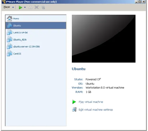
1. WMWare player version 5.0. Available at www.wmware.com (free download and use). This software is already installed in the laboratory desktop computer.
2. A VMWare virtual machine with Ubuntu 12.04 and all the software packages installed si already available in the Desktop. This virtual machine is available for your personal use at the Department assistance office (preferred method). If you want to setup your virtual machine by yourself follow the instructions provided in the Annex I.
3. A BeagleBoard with the power supply and cable, connectors is available at ISE laboratory.
3.2
Starting the VMware
Start WMware player and open the ISE Virtual Machine. Wait until the welcome screen is displayed (see Fig. 1 and Fig. 2). Login as ”ISE” user using the password “ise.2013”. A Ubuntu tutorial is available at moodle site.
Fig. 2: Ubuntu Virtual Machine login screen.
Open the firefox web browser and download from http://buildroot.uclibc.org/ the version identified as buidlroot2012-02-rc1 (use the download link, see Fig. 3, and navigate searching for earlier releases). Save the file to the Documents folder in your account (Fig. 4).
Fig. 4: Downloading buildroot source code.
Using the file explorer navigate to the Documents folder and decompress the file (Fig. 5).
Fig. 5: Buildroot folder.
Right click in the window and execute “Open in Terminal”. In some seconds a command window is displayed. Then, execute these commands:
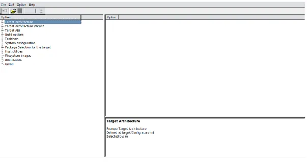
In some seconds you will see a new window similar to Fig. 6.
[Help]: In Linux “TAB” key helps you to autocomplete de commands, folders and files names.
ise@ubuntu:~/Documents$ cd buildroot-2012.02-rc1
Fig. 6: Buildroot setup screen.
3.3
Configuring Buildroot.
Once Buildroot configuration is started, it is necessary to configure the different items. You need to navigate through the different menus and select the elements to install. Table I contains the specific configuration of Buildroot for installing it in the BeagleBoard.
Table I: Parameters for Buildroot configuration
Main Item Subitem Value Comments
Target Architecture ARM Target Architecture Variant Cortex A8
Target ABI EABI An embedded-application
binary interface (EABI) specifies standard conventions for file formats, data types, register usage, stack frame organization, and function parameter passing of an embedded software program.
Build options How Buildroot will built the
code. Leave default values.
Toolchain Cross Compiler, linker,
libraries to be built to compile out embedded application
[Help]: The Buildroot configuration is an iterative process. In order to set up your embedded Linux system you will need to execute the configuration several times..
Main Item Subitem Value Comments
Toolchain Type Buildroot toolchain Embedded system will be compiled with tools integrated in Buildroot Kernel Header
Kernel Header Options
Version 3.2.x Source header files of the Linux Kernel.
uClibc Options Version 0.9.31 Library (small size version) containing the typical C libraries used in Linux environments (stdlib, stdio, etc)[RD6]
Thread library debugging Select Embedded system will have debugeable threads,
Binutils Options Version 2.20 Leave default values [RD7]. Binutils contains tools to manage the binary files obtained in the compilation of the different applications
GCC Options Version 4.5.x GCC tools version to be
installed
Install Objective C Install objective C compiler Shared Libraries in GCC Support for shared libraries
GDB GDB server
GDB host GDB version 7_4
Includes the support for GDB. GCC debugger.
Enable MMU support Mandatory if building a Linux
system
Use software floating point Floating point will be
implemented by software and not in hardware
Enable WCHAR Support for extender set of
chars.
Enable C++ support Including support for C++
programming, compiling, and linking.
Enable Pthreads old
System Configuration
System Hostname Buildroot Name of the embedded
system
System Banner Linux ISE Banner
/dev management Static using device table Embedded Linux typically uses static device
Main Item Subitem Value Comments
management Path to permissions table target/generic/device_t
able.txt
Text files with permissions for /dev files
Path to the device tables "target/generic/device_ table_dev.txt"
Files to be created in /dev in the embedded system
Root filesystem skeleton Default target skeleton Linux folder organization for the embedded system
Port to run a getty ttyO2 Linux device file with the port to run getty (login) process Baud rate to use 115200
remount root filesystem read-write during boot
yes Custom script to run before creating filesystem images
Package
Selection for the target
Busybox
Busybox version 1.19 Audio and video libraries
and applications
Default
Compressors and
decompressors
Default Debugging, profiling and
benchmark
Default Development tools
Games
Graphic libraries and applications (graphic/text) Hardware handling
Interpreters language and scripting Libraries Default Miscellaneous Networking applications Package managers Real Time
Shell and utilities System Tools
Default
Miscellaneous System Tools
Text Editors and viewers
Main Item Subitem Value Comments
Networking applications Default Package managers Default
Real Time Default
Shell and utilities Default Text Editors and viewers Default
Host utilities
host openocd No
host sam-ba No
host u-boot tools Yes
Filesystem Images
cramfs root filesystem No cloop root filesystem for the target device
No
ext2 root filesystem Size 64000 Gzip jffs2 root filesystem No ubifs root filesystem No squashfs root filesystem No tar the root filesystem No cpio the root filesystem No initramfs for initial ramdisk of linux kernel
No omfs root filesystem No
Bootloaders
Barebox
U-Boot U-Boot board name:
omap3_beagle
U-Boot Version: 2011.09 custom patch dir
U-Boot binary format: uboot.bin
Custom Network
Settings
x-loader x-loader board name:
omap3530beagle
Linux Kernel
Kernel version 3.2.5
Custom kernel patches
Main Item Subitem Value Comments file /home/ise/Documents/ buildroot-2012.02- rc1/output/build/linux-3.2.5/arch/arm/configs /omap2plus_defconfig
Kernel binary format uImage Install kernel image to
/boot in target
No Linux Kernel Extensions Nothing
Once you have configured all the menus you need to exit saving the values (File->Quit).
3.4
Adding devices to the Linux embedded system in /dev folder
In Linux /dev folder is essential in order to manage all the devices correctly. This folder must have and entry (a file) in order to use the hardware elements in your embedded systems. Beagleboard has three serial ports named as /dev/ttyO0, /dev/ttyO1 and /dev/ttyO2. In the beagleboard ttyO2 is physically available in a header and this header has a cable with 10 pin connector. This connector should be connected to the host computer. In order to define these devices in the embedded Linux you need to add specific information in the file ./target/generic/device_table_dev.txt.
Execute this command
and add this entry the file.
[Help]: The Buildroot configuration is stored in a file named as “.config”. You should make a backup of this file.
[Help]: In the buildroot configuration there is an item to setup the “System Configuration” (see Table I). In this item you are specifying the file that contains the devices to be created in the embedded Linux. By default, this file could not contain your specific hardware. In the case of the Beagleboard ttyOn ports are not defined.
/dev/ttyO c 777 0 0 58 65 0 1 3
Fig. 7: File device_table_dev-txt with ttyO entry.
3.5
Compiling buildroot.
In the Terminal Window executes the following command:
If everything is correct you will see a final window similar to the represented in Fig. 22.
[Time for this step]: In this step buildroot is going to connect, using internet, to different repositories. After downloading the code, Buildroot is going to compile the applications and generates a lot files and folders. Depending of your internet speed access and the configuration chosen this step could take up to one hour.
Fig. 8: Successful compilation and installation of Buildroot
Buildroot has generated some folders with different files and subfolders containing the tools for generating your Embedded Linux System. Next paragraph explains the main outputs obtained,
3.6
Buildroot Output.
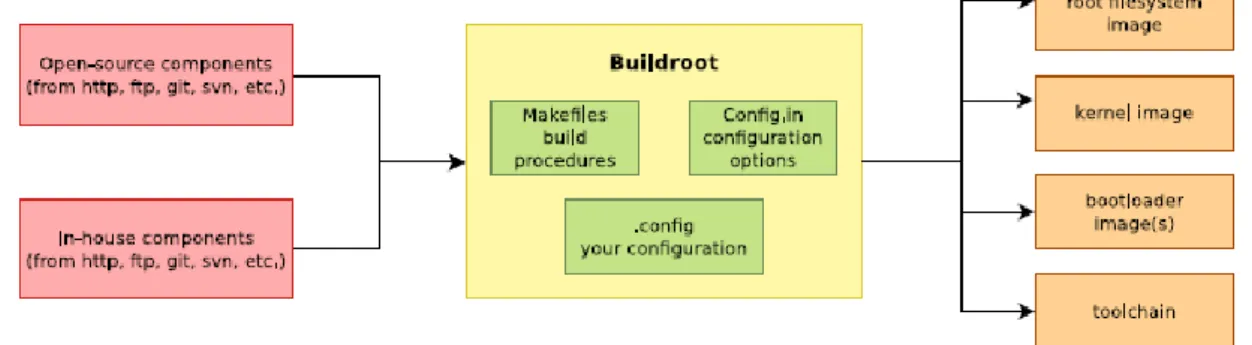
The main output files of the execution of the previous steps can be located at the folder “./output/images”. Fig. 9 summarizes the use of Buildroot. Buildroot generates a boot loader, a kernel image, and a file system.
Fig. 9: Schematic representation of the Buildroot tool. Buildroot generates the root file system, the kernel image, the booloader and the toolchain. Figure copied from “Free Electrons” training materials
(http://free-electrons.com/training/)
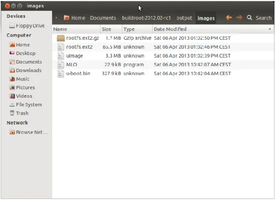
Fig. 10: images folder contains the binary files for our embedded system.
These files must be copied to a SD card for booting BeagleBoard. MLO contains the X-loader bootloader, u-boot.bin contains the u-boot application for booting your Linux. Linux image is uImage and rootfs.ext2.gz contains the file system compressed. The file rootfs.ext2 is the decompressed version of rootfs.ext2.gz and is not necessary for booting.
3.7
Booting the Beagleboard.
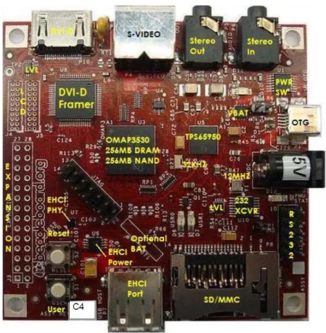
Fig. 11 displays a Beagleboard. The description of this card, their functionalities, interfaces and connectors are explained in the ref [RD5]. In the basic connection we need to connect the RS232 cable to the header with this identification in the figure and the power supply (5 v) in the corresponding plug.
Fig. 11: Beagleboard (rev C4) hardware with main elements identified.
Now, connect the Beagle board to the Host PC using the serial cable. In the Linux machine, or in the windows machine, open a Terminal and execute the program putty (or hyperterminal), in a seconds a window will be displayed. Configure the parameters using the information displayed in Fig. 12 (for the specific case of putty), and then press “Open”. You will see the information shown in Fig. 13 showing the booting process of BeagleBoard.
Fig. 12: Putty program main window.
[Serial interface identification in Linux]: In Linux the serial devices are identified typically with the names /dev/ttyS0, /dev/ttyS1, etc. In the figure the example has been checked with a serial port implemented with an USB-RS232 converter. This is the
Fig. 13: Serial output in the beagleBoard boot process.
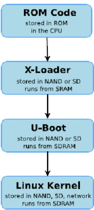
The default Beagleboard boot process is this: NAND -> USB -> UART -> MMC. Fig. 14 represents the different boot steps. The OMAP processor searches, in its internal ROM, for the code for the basic loader. This loader try to find the X-Loader first in the NAND and secondly in the SD Card. Once X-Loader has been executed this searches for the u-boot loader in the NAND memory or in the SD card. In Fig. 13 you can see the basic boot using the NAND memory. The Beagleboard boot process is different upon the value of the “user button”. If user button is not pressed in the reset the boot sequence is this: NAND -> USB -> UART -> MMC, otherwise is USB -> UART -> MMC -> NAND.
reason of why the name is /dev/ttyUSB0. In your computer you need to find the identification of your serial port.
Fig. 14: Boot sequence in the BeagleBoard. Figure copied from “Free Electrons” training materials (http://free-electrons.com/training/).
If we want to boot the beagle using the SD card, we need firstly to format properly the SD card. The steps to do this are described in this reference [RD10] .An alternative method to format the SD card is the use of
HP USB Disk Storage Format Tool.
Once you have the SD formatted, copy the all the file of the images buidlroot folder to the SD card. Eject the SD card from the Linux machine, insert SD card in the BeagleBoard and push the reset button S2. In the output of the putty terminal you will see some boot messages (see Fig. 15).
Fig. 15: Booting messages in the serial line.
In this moment u-boot is running and you can introduce u-boot commands in order to start the execution of your system. Execute the following commands:
The meaning of the different command is explained in Table II.
mmc rescan mmc list
setenv bootargs console=ttyO2,115200n8 root=/dev/ram rw ramdisk_size=65536 initrd=0x81600000,64M init=/sbin/init echo "Bootargs"
fatload mmc 0 0x80200000 uImage echo "uImage loaded from mmc" fatload mmc 0 0x81600000 rootfs.ext2.gz echo "rootfs.ext2.gz..."
Table II: u-boot parameters
command explanation
mmc rescan Scan the availability of a MMC device
mmc list List MC devices available in the system
setenv bootargs console=ttyO2,115200n8 root=/dev/ram rw ramdisk_size=65536 initrd=0x81600000,64M init=/sbin/init
Set the environment variables of u-boot. These variables are needed for a correct boot of Linux system
Console is the serial line to display the boot messages (ttyO2 using 8 bits and 115200 baud rate)
Root is the device containing the main partition to mount. Here we are using RAM memory to mount the filesystem
Rw filesystem y read/write
Ramdisk_size and initrd are parameters related with the size and location of the filesystem in the memory
Init is the first process to execute in Linux (tipically this)
fatload mmc 0 0x80200000 uImage Load from a MMC formatted as FAT32 the file uImage in
address 0x80200000. uImage constains the kernel image.
fatload mmc 0 0x81600000 rootfs.ext2.gz Load from a MMC formatted as FAT32 the file
rootfs.ext2.gz in address 0x81600000. Rootfs.ext2.gz contains the file system compressed. This file will be uncompressed by Linux in the booting stage.
bootm 0x80200000 Boot the program starting at address 0x80200000. We
are booting the kernel
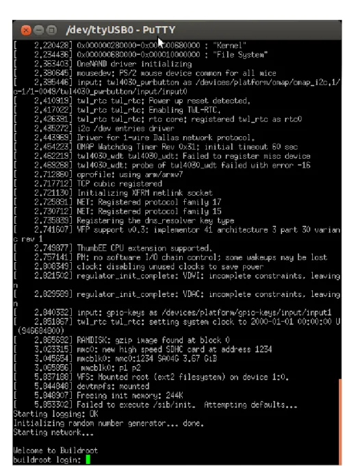
After some seconds you will see a lot messages displaying in the terminal. Linux kernel is booting and the operating system is running its configuration and initial daemons. The output will be similar to Fig. 16. If the system boots correctly you will see an output like the represented in Fig. 17. Introduce the user name root and the Linux shell will be available for you.
Fig. 17: Beagle running Linux.
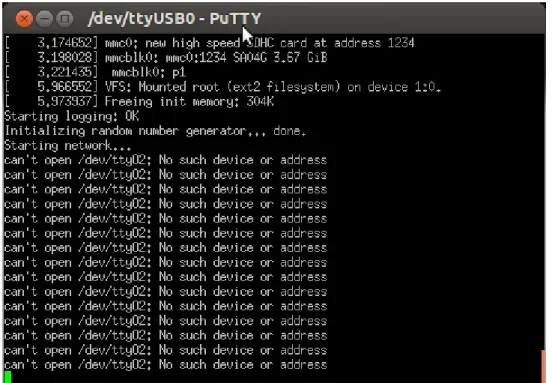
[Errors]: In the specific case of this exercise BeagleBoard is not booting. You are going to see a message like this: “can't open /dev/ttyO2: No such file or directory”. Next paragraph provides the solution for solving this error. Probably, 90% of the typical problems when booting Linux are solved configuring correctly your kernel in order to support all the hardware available in your embedded system with the correct drivers. If everything is ok .probably you have your Linux running in your system. But for sure your system is not booting or you are not obtaining the Linux shell running. Check the specific error with your instructor to find a solution. Any missing parameter in Buildroot configuration or in the kernel configuration can generate an error in the booting of your system.
3.8
Configuring the Linux kernel parameters
In all the Linux embedded applications it is necessary to set up the kernel in order to support the different l physical devices and user space applications. All kernel sources provide a basic configuration for specific hardware platforms. If you are using a commercial hardware platform probably you will find a kernel configuration suitable for you, if not you will need to define it. This is a hard task but you will find hundreds of examples in Internet. Linux kernel has a directory with hardware configurations. The relative path is this:
“./Documents/buildroot-2012.02-rc1/output/build/linux-3.2.5/arch/arm/configs”. Have a look to this folder and you will find this file: omap2plus_defconfig. Unfortunately, this kernel configuration file doesn’t include all the possible configurations of beagleboard. In order to add the support for serial line in ttyO0-2 we need to add a specific feature to Linux kernel. Execute this command:
You can navigate in this application (Fig. 18) using the arrows. Go to Device drivers (Fig. 19), Generic Driver Options (Fig. 20), and select “Maintain a devtmpfs…” and “Automount devtmpfs…… ” (Fig. 21).
Fig. 18: Linux kernel configuration
Fig. 19: Device drivers is selected.
Fig. 21: Selection of devtmpfs feature.
Now, select <Exit> to return to main window and save the changes, then execute:
If everything is correct you will see a window similar to the represented in Fig. 22.
Fig. 22: Successful compilation and installation of Buildroot
Now, boot the Linux following the instructions explained in the previous point. Remember to copy the files available in the image folder to the SD card.
[Time for this step]: In this step buildroot is going to recompile the Linux kernel. Depending of your computer this could last five to ten minutes.
3.9
Booting the Beagleboard using a script.
The previous step aforementioned for starting up the Linux can be simplified a little bit using a u-boot script. If you create a text file with the u-boot commands you obtain a binary script using the following command:
Copy the boot.scr into the SD card y reboot BeagleBoard pressing the S2 reset button. Now you can run Linux system executing the following commands:
3.10
Mounting the SD card partition as a Linux visible partition
Until now we have been using the SD Card as a media for booting the BeagleBoard. Now we are interested in the use of SD card partition as a partition visible for embedded Linux. The way to do this is :
[SD card use]: You can copy all the files that you need in your Embedded Linux in the SD card. Mounting the SD allows you to execute programs compiled for the ARM processor..
mkdir /mnt/sdfilesystem
mount /dev/mmcblk0p1 /mnt/sdfilesystem cd /mnt/sdfilesystem ls –lasg mmc rescan mmc list fatload mmc 0 0x80000000 boot.scr source 0x80000000
4
LAB2: CROSS-COMPILING APPLICATIONS FOR
BEAGLEBOARD
4.1
Hello Word application.
The simplest application to be developed is the typical “Hello Word” application. Open a terminal in the Linux machine. Create a folder named “hello”, change the directory to it and execute “gedit main.c” edit the program and save it.
Fig. 23: Basic hello world program in C.
The next step is to compile the program. Remember that we are developing cross applications. We are developing and compiling the code in a Linux x86 machine and we are executing it in an ARM architecture (see Fig. 24).
Fig. 24: Summary of the different configurations for developing applications for embedded systems. Figure copied from “Free Electrons” training materials (http://free-electrons.com/training/)
The first question is where the cross-compiler is located. The answer is this: in the folder “buildroot-2012.02-rc1/output/host/usr/bin”. If you inspect the content of this folder you can see the entire
compiling, linking and debugging tool (see Fig. 25). These programs can be executed in your x86 computer but will generate code for ARM processor.
Fig. 25: Folder containing the cross compiling tools.
The second question is how to invoke the command to compile the code. Typically in Linux we use gcc command and some parameters. Previously to answer this question we are going to add the location of the cross-compiling tools to the Linux path. To do that you need to edit in your home directory the “.profile” file and add the corresponding path (see Fig. 26). Once you have edited the file you need to logout and login again.
[Changes in .profile]: changes in .profile file only have effect in you execute a logout and login again into your account.
Fig. 26: Adding the cross compiler PATH to the Linux .profile file.
In this point we can compile and execute our first cross-compiled program. Execute this command:
Now you can copy the “main” executable to the SD card and reboot the BeagleBoard. Remember to mount the SD card in Linux and then execute the main program.
5
LAB 3: ADDING SUPPORT FOR COM2 SERIAL PORT TO
BEAGLEBOARD.
5.1
Hardware support.
Beagleboard includes three hardware serial ports. These serial ports are integrated in the OMAP processor. Physically, only serial port 3 is available directly in a header connector (see Fig. 27 and Fig. 28).
Fig. 27: Serial port header.
Fig. 28: Schematic of the UART 3 serial port interface.
The two additional ports UART1 and UART2 are not available directly to be used. In order to provide an additional serial port to the beagle we need to provide a hardware interface and a connector. The solution has been to develop a specific hardware interface that is connected to the expansion connector.
Fig. 29: Beagle expansion connector.
In order to set up UART2 and to have the signals available it is necessary to program a multiplexer in the OMAP chip. Next paragraph explains how add support for this in our embedded Linux. The technical details of this can be found in [RD11].
5.2
Configuring OMAP multiplexer for connecting ttyO1 to the physical
connector
The configuration of the multiplexer can be provided both at kernel level or u-boot level. We have tested both methods and here we are explaining how to proceed to setup using uboot.
Adding this extra configuration for uboot requires modifying uboot source code and then recompiles it. The process is explained now. Execute the following command:
If you list the content of the folder you will see this:
Fig. 30: Files included in uboot for supporting Beagleboard.
Now edit the “beagle.h” header file and add the code as explained in[RD11] (see Fig. 31 )
ise@ubuntu:~$ cd Documents/buildroot-2012.02-rc1/output/build/uboot-2011.09/
Fig. 31: Configuration of the OMAP MUX for supporting the UART2.
Save and close the file. Now open the “beagle.c” and include the code as shown in Fig. 32. With this modification we will see a message in the u-boot initialization telling us that uboot has been modified for supporting UART2.
Fig. 32: Adding code to initialization for display a message.
Now save the file, close gedit and return to home directory.
Now, we need to recompile uboot for obtaining the image suporting UART2. The commands are:
ise@ubuntu:~$ cd Documents/buildroot-2012.02-rc1/output/build/uboot-2011.09/
ise@ubuntu:~/Documents/buildroot-2012.02-rc1/output/build/uboot-2011.09$ make ARCH=arm CROSS_COMPILE=arm-linux-
In the uboot folder copy the uboot.bin image to the SD card and reboot Linux in the BeagleBoard.
5.3
Running microcom for testing serial ports in BeagleBoard
Once Linux is running you can check this new serial port using the command :
Open a new putty terminal in Linux using another serial port and check the comunication.
[u-boot build]: With this step you have compiled only uboot.
6
LAB4: ADDING SUPPORT FOR THE USB TO ETHERNET
INTERFACE
In this LAB we are going to connect a USB-Ethernet device to the BeagleBoard. The first step that we need is to configure the kernel for supporting USB. Execute:
Navigate in the kernel configuration until you locate the support for the EHCI HCD (USB 2.0) and EHCI support in the OMAP processor (see Fig. 34 and Fig. 34).
Fig. 33: Including support for USB
Fig. 34: Adding support for EHCI in Beagleboard.
Now, locate the USB Ethernet adapters in the Device Driver support. In this LAB we are going to use an Ethernet adapter based in the MCS7830 chip (see Fig. 35). Exit from kernel configuration saving the changes and compile Buildroot using make command. The compilation will last between 5 and 10 minutes.
Fig. 35: Adding support in the Kernel for USB-Ethernet adapter
Fig. 36: Kernel compilation including support for USB to Ethernet interface.
Copy the files in the buildroot images folder and reboot Linux in the BeagleBoard.
Execute the following command to identify the USB devices detected by the Linux Kernel.
# lsusb
Bus 001 Device 001: ID 1d6b:0002 Bus 001 Device 002: ID 9710:7830
And now execute these commands to start up the Ethernel interface and the TCP/IP protocol. If everythink is correct your Ethernet interface will be running. In order to test the network you need to connect a cable (directly to your computer) and add in your desktop or labtop computer an address in the range 192.168.x.x. Use the ping command to test the communication.
# ifconfig eth0 up
# ifconfig eth0 192.168.1.2 # ifconfig
eth0 Link encap:Ethernet HWaddr 00:13:3B:04:01:08
inet addr:192.168.1.2 Bcast:192.168.1.255 Mask:255.255.255.0 UP BROADCAST RUNNING MULTICAST MTU:1500 Metric:1 RX packets:0 errors:0 dropped:0 overruns:0 frame:0 TX packets:0 errors:0 dropped:0 overruns:0 carrier:0 collisions:0 txqueuelen:1000
RX bytes:0 (0.0 B) TX bytes:0 (0.0 B) lo Link encap:Local Loopback inet addr:127.0.0.1 Mask:255.0.0.0
UP LOOPBACK RUNNING MTU:16436 Metric:1 RX packets:0 errors:0 dropped:0 overruns:0 frame:0 TX packets:0 errors:0 dropped:0 overruns:0 carrier:0 collisions:0 txqueuelen:0
RX bytes:0 (0.0 B) TX bytes:0 (0.0 B) #
7
LAB5: USING INTEGRATED DEVELOPMENT
ENVIRONMENTS: CODE::BLOCKS AND ECLIPSE/CDT
7.1
Cross-Compiling application using Code::Blocks integrated
development environments.
In the virtual machine you have an IDE to developed C and C++ applications. This environment is the CodeBlocks framework. Execute it and you will obtain the screen shown in Fig. 37.
Fig. 37: Main screen of Code::Blocks environment.
The first step to use Code::Blocks is to setup the cross-compiling tool installed for developing with Beagle-Board. In the settings menu select “Compiler and debugger settings” (see Fig. 38). The. first step is the creation of a new configuration. Use the copy button for copying the “GNU ARM GCC compiler” setup. In this window please move to “search directories” tab. Add the path shown in Fig. 39
Fig. 38: Creating a configuration for the cross-compiler in Code::Blocks.
Fig. 39: Configuration of the include directory for cross tools.
Fig. 40: Linker search directories for cross-linking.
The last step is the configuration of the specific programs for compiling, linking, debugging, etc. Fig. 41 shows the names of the different programs.
Fig. 41: Configuration of the applications for cross tools.
Once you have introduced the configuration information, save them and return to the main Code::Blocks Window. Start the development of a project using the option File, New Projetc. The envoriment is very intuitive and ease of use.
Create a C project. By default, Code::Blocks will generate the “hello world” application. The executable is located under project folder under the bin/debug subfolder. Copy the executable to the SD Card reboot Beagle and test the program. If we want to debug remotely this program we can use the gdb and gdbserver applications. In the Beagleboard execute the following command:
Fig. 42: gdbserver running waiting for connection.
In Code:.Blocks select Debug->Start. You will see the debug window (seeFig. 43 ). Insert a breakpoint in the printf sentence.
Fig. 43: Code::Blocks running the gdb debugger.
In the lower part of this window insert in the Command box the following instructions: target remote 192.168.1.2:2345. Then, select Debug->Continue and the program will stop in the printf sentence. Display the Beagle console to see the message. Now, you are debugging remotely your application.
7.2
Cross-Compiling application usingEclipse.
In a Terminal window start Eclipse with the following command:
The popup window invites you to enter the workspace (see Fig. 44). The workspace is the folder that will contain all the eclipse projects created by the user. You can have as many workspaces as you want.
Fig. 44: Selection of the workspace for Eclipse.
Select Ok and the main window of Eclipse will be shown. Next close the welcome window and the main eclipse window will be displayed.
[Advice]: Every time you compile your application you need to move the executable file to the target. If you don’t follow this rule the execution and debugging will give unpredictable results.
Fig. 45: Eclipse welcome window.
Fig. 46: Eclipse main window.
Create an Eclipse C/C++ project (File->New->Project) selecting the hello world example (see Fig. 47 y Fig. 48).
Fig. 47: Creation of the hello world C project.
Click on the Finish button and you will obtain your first project created with eclipse.
The next step is to configure the Eclipse project for managing the Cross-tools. In project ->properties configure the C/C++ Build Setting as the Fig. 49 and Fig. 50shown.
Fig. 49: Tool Chain Editor should be configured to used Cross GCC.
Fig. 50: Cross tools locate on (path)
The next steps is to configure the search paths for the compiler and linker, and the different tools to use. Complete the different fields with the information included in Fig. 51 and Fig. 52.
Fig. 51: Include search path.
Fig. 52: Libraries search path.
Once you have configured the cross chain in Eclipse you can build your project using Project->Build Project. If everything is correct you will see the eclipse project as represented in Fig. 53.
Fig. 53: Eclipse project compiled (Binaries has been generated).
The next step is to copy the executable program to the SD card, reboot the Beagleboard and execute the program using the gdbserver as aforementioned. Now, it is time to setup the debugging session in Eclipse environment. Select Run->Debug Configurations and complete the different tabs following the indications of Fig. 54, Fig. 55, Fig. 56 and Fig. 57
Fig. 55: Configuration must be set to manual remote debugging.
Fig. 57: Configuration of the remote target. Port number must be the same in the target and in the host.
8
PREPARING THE LINUX VIRTUAL MACHINE.
8.1
Download VMware Player.
The document http://www.vmware.com/pdf/VMwarePlayerManual10.pdf describes the installation and basic use of VMware Player. Follow the instructions to setup the application in your computer.
8.2
Installing Ubuntu 12.04 LTS as virtual machine.
The first step is to download Ubuntu 12.04 form Ubuntu web site using this link:
http://www.ubuntu.com/download/desktop/thank-you?release=lts&bits=32&distro=desktop&status=zeroc . You will download an ISO image with this Linux operating System.
Run WMware player and install Ubuntu using the VMWare player instructions. A tutorial explaining this can be found here (http://www.computersecuritystudent.com/UNIX/UBUNTU/lesson1/)
8.3
Installing packages for supporting Buildroot.
The annex I contains the instructions for downloading the list of pakages installed in the Ubuntu 12.04 LTS in order to run correctly Buildroot tools.
9
ANNEX I: UBUNTU 12.04 LTS PACKAGES INSTALLED.
9.1
List of packages installed in the Ubuntu OS.
In the moodle site there is a test file with a list of all the packages installed in the Ubuntu OS.
9.2
Installing software in Ubuntu 12.04 TLS
If you download that file you can replicate the installation using these commands:
sudo apt-get update sudo apt-get dist-upgrade
sudo dpkg --set-selections < iseubuntu-files sudo dselect install