Journal of Criminal Law and Criminology
Volume 37 | Issue 3
Article 8
1946
The Comparison Camera
J. H. Mathews
Lee K. Henke
Follow this and additional works at:
https://scholarlycommons.law.northwestern.edu/jclc
Part of the
Criminal Law Commons
,
Criminology Commons
, and the
Criminology and Criminal
Justice Commons
This Criminology is brought to you for free and open access by Northwestern University School of Law Scholarly Commons. It has been accepted for inclusion in Journal of Criminal Law and Criminology by an authorized editor of Northwestern University School of Law Scholarly Commons.
Recommended Citation
of
POLICE SCIENCE
THE COMPARISON CAMERA
J. H. Mathews and Lee K. Henke
Dr. Mathews is Chairman of the Department of Chemistry and Director of the Four Year Chemistry Course at the University of Wis-consin. His interest in scientific methods of criminal identification dates back to the Magnuson bomb case in 1923-a case in which an identifica-tion was made by metallographic analysis. After this experience he was soon called upon to identify a rifle from a fired murder bullet. Working with meager equipment he was successful in building up a case that resulted in a confession during the course of the trial. Since that time he has been called on for assistance by the law enforcement agen-cies of Wisconsin on hundreds of occasions and has built up one of the best scientific crime laboratories in the country. A considerable num-ber of new and improved instruments have been built in collaboration with Mr. Henke who is Senior Mechanician in the Chemistry Depart-ment. Mr. Henke has had many years of experience as an instrument designer and mpker.-EDITOR.
Those of us who for years-have had occasion to use a com-parison microscope for the examination of bullets and other objects know how very tiring such examinations may become. Not only are they tiring but they are productive of eye-strain. Both of these difficulties disappear with the use of the com-parison camera - the basic idea of which was suggested by May and by Lewis. The operator sits in a comfortable posi-tion looking directly ahead at images on a large ground glass screen. The images are large and clear and are seen by both eyes and are viewed at a normal and comfortable distance, thus materially reducing eye-strain.
A series of knurled control knobs, placed in line a few inches below the ground glass, and one at either side of the ground glass, enable the operator to move the specimens in any desired direction and rotate them. After all adjustments of the two juxtaposed images have been made, one sees on the ground glass exactly what he may expect to see in the finished photograph. A time switch enables him to expose for a pre-determined length of time.
Both plates and cut films may be used. Eastman Panatomic film is very satisfactory because of its lack of grain and its sen-sitivity to all colors.
J. H. MATHEWS AND LEE K. HENKE
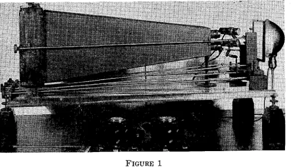
FIGURE 1
The Comparison Camera and Rheostats for Light Control
The Carriage
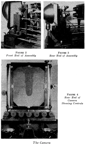
This part of the instrument (Figs. 2 and 3) has in its as-sembly the mechanism for transmitting vertical, horizontal, longitudinal and circular motion to specimens being compared and photographed. It is so arranged that the image of one object may be juxtaposed above the other, exactly. The car-riage travels on a pair of 12" square tracks, 8" in length, secured to the base of the instrument and is actuated by a " lead screw (G in Fig. 4) and having 28 threads to the inch. All lead screws are of the same diameter and pitch throughout. Rising from the carriage are two supports capable of being moved to the right or left independently of each other by means of two inclined planes and aftuated by individual lead screws (H1 and H2 in Fig. 4). Each of these supports carries
a bracket to which is attached a small worm and worm gear so arranged that there is virtually no back lash. These worm gear assemblies impart circular motion to the specimens they carry, by turning knobs R1 and R2 in Fig. 4. The brackets
are moved vertically by means of inclined planes built into the supports. The planes are moved by lead screws (V1 and V2 in
FIGURE 2 FIGURE 3
Front End of Assembly Rear End of Assembly
~FIGURE
4Rear End of Camera Showing Controls
The Camera
J. H. MATHEWS AND LEE K. HENKE
The lens rings carry a matched pair of Bausch and Lomb lenses. Various focal length lenses are available, a pair of 112 mm. Tessar Ic lenses are used for low magnifications, a pair of 70 mm. focal length Micro Tessars for greater magnification. The unique feature of the camera body is the fact that it con-tains an adjustable thin metal partition dividing the camera horizontally into two separate parts, one for each lens. This partition is surfaced with sateen cloth and sprayed with in-strument black. (a non-glossing lacquer) to prevent halo and ghost images, as the angle of incidence is very low, less than 15 degrees at times. There is no reflection from this metal partition. It is slip hinged at the lens end and supported at the plate end by two bearing blocks through which run two finely threaded vertical rods, one at each side of the plate holder but out of line with the light path. A single control knob (D in Fig. 4) at the top of the rear end of the camera, permits the adjustment of this dividing partition lip or down, the two
threaded rods being rotated in synchronism by means of a con-necting chiin and sprocket drive. The movement of the
par-tition permits the making of comparisons of specimens at any point in their length. The rear of the camera is fitted with a conventional 8" x 10" plate back with ground glass permitting the use of standard 8" x 10" cut film or plate holders.
The Base
The base of the instrument is a 1" thick American black walnut board edged with a modified "OG" bead all around. Inset on the under side of this base are two pieces of cold rolled steel " x 1" through which are threaded the three adjusting
screws whose ends terminate in knurled knobs, thus giving a three point support for the instrument. In order that the op-erator may be seated, in a normal position at the instrument, the entire assembly is set on three pyramidal wood blocks of the correct height for the operator's eye level.
Materials used throughout are stainless steel and brass ex-cept the inclined planes whose-bearing surfaces are faced with cold rolled steel. All exposed brass surfaces are finished with black Hilo crystallizing varnish ("crackle finish"). The cam-era body is covered with Kcam-eratol (simulated leather) and the base is piano finished (several coats of clear Valspar varnish, hand pumiced and polished).
Lighting Equipment
FIGURE 5
252 J. H. MATHEWS AND LEE K. HENKE
75 watt light bulb in a desk type reflector, thus providing a white background for the objects being photographed.
There are two adjustable microscope type object illumina-tors (Spencer) which are so positioned that they give oblique lighting to the specimens. These lights are controlled by two rheostats (shown in Fig. 4) so their intensity can be matched or balanced. This is important as a test bullet is usually brighter than the evidence bullet.