University of South Australia
School of Advanced Manufacturing and Mechanical Engineering DEFECT DETECTION IN HIGH PRESSURE DIE CASTING PRODUCT
USING IMAGE PROCESSING TECHNOLOGY by
Wahab, Md Said in Student 10:
100008279
Under the supervision of Dr. Lingxue Kong
A thesis submitted in partial fulfilment of the requirement for the degree of
Disclaimer
Abstract
In this thesis an Automated Visual Inspection (AVI) system for ckl'eel dL'lc'L'li"i1 ('( 111~h
Pressure Die Casting (HPDC) product has been dcveloped, The sy,lelll i, l'i1;lblin~ 1(\
detect external structural defects of the product particularly for crack and Iwk. This lhesi, also describes detailed procedures based on image processing technnl,,~} IIhich include enhancement/preprocessing, segmentation, codingifeature extractinn and I III age analysis/classification/interpretation, The commercial Matlab image processing kls been used to implement these procedures, An intelligent approach based on mllrpllOlog~ and fuzzy logic is proposed to detect such structural defects on the surface.
The proposed method has been implemented and tested on a number of 111'1)(' I'rllducl. The results suggest that the method provide an accurate identification tn lhe dekelS and be extended for further application, The results also suggest that the system 1I('rk lIell enough to help die casting manufacturer to improve the value or die Glsling I,rllduc\ lil;11 they can obtain from automated inspection system,
A few suggestions have been discussed for future research to address the limiwlillns of this research.
Acknowledgments
I wish to express m)' sincerest thanks to my advisor. Dr. Lingxue f--:.!lng rllr hi, gllld;lllc'C', paticncc, and support throughout this thcsis, especially through the tillle, \'. hc'lI thL' writing bccamc di fficul t.
Special thanks to my wife Anizam Mohamed Yusofand my childrcn !l1ms) id;lh & 1 );lni;tI for their love and encouragement. I dedicate this thcsis to my parcl1b It)r their ullll;lgging faith in mc, \Vithout thcir dcvotion, support. patiencc, and encourageillent thr()lIglh llit thc' pcriod of study. this work would not have bcen possible,
Contents
1. Introduction ... .
1.1. The background of the problem ... . 1.2. Problem addressed to die casting ... .
1.3. Suggested solution ... .. "
.'
IA. Aim/objective of the project... 4
1.5. Scope and limitation.. ... 4
1.6. Thesis roadmap... 5
2. Litcl'atLlI'c Rcvic'v ... 6
2.1. Die Casting Process... 6
2.1.1. Hot chamber machine... 7
2.1.2. Cool chamber machine... g 2.2. The advantages of die casting process... 10
2.3. Application of die casting... ... 12
2A. Die casting defect... 13
2.5. Current inspection quality control process... 17
2.6. Overview of Human Vision andlvlachine Vision ... 18
2.6.1. Human Vision... . ... 18
2.6.2. Machine Vision... 19
2.7. An artificial intelligence in vision system for decision making ... .. ,),,1
2.8. Summary ... . 24
3. Imagc Acquisition and Storagc ... 25
3.1. Introduction ... .
6. Conclusions and "ccoI11mcndations ... M,
6.1. Introduction ... . 6.2. Achievement. ... .
6.3. Recommendation for future work ... 7()
Appcndixcs
Appendix A Typical defects in die casting ... 75 Appendix B Comparison of human vision. machine vision and compliter \·isioll.:;n Appendix C Matlab Code... .. ~~
Figures and Tables
Figures
Figure 2.1 Figure 2.2 Figure 2.3 Figure 2.4 Figure 2.5 Figure 2.6 Figure 2.7 Figure 2.8 Figure 2.9 Figure 3.1 Figure 3.2 Figure 3.3 Figure 3.4 Figure 3.5 Figure 4.1 Figure 4.2 Figure 4.3 Figure 4.4 Figure 4.5 Figure 4.6 Figure 4.7Hot chamber machine .... '" ... 7
Cool chamber Machine ... 9
Commercial High Pressure Die Casting machine ... 9
Process economic for die casting ... 10
Die casting end user 2003 ... '" ... " .. 12
Sample of crack defect. ... 15
Sample of hole I ... 16
Sample of hole 2 ... 16
Industrial manufacturing cell with vision system ... 20
Vision inspection system procedure ... 26
Front lighting system ... 28
Backlighting system ... " ... ' ... 28
Structured lighting system ... 29
(a) Image matric presented in pixel (b) image appear in the screen and (c) graycale value corespond to the intensity of the image ... 31
(a) Original image. and (b) image after wiener filter. ... 36
A histogram computed from image after wiener process ... 39
Threshold is set at> 60 ... 40
Threshold is set at> 1 09 ... . ... .41
A negative image after morphological operation ... . . ... 47
Background of the image... ... ... ... ... 48
Image after background subtraction process... 48
Figure 4.8
Final image after segmentation operation ... -1')
Figure 4.9
~Pseudocolor index image for matrix A ...
~
I
Figure 4.10
Pseudocolor index image for three objects ...
~2
Figure 4.11
Ellipse orientation... (,()
Figure 5.1
A final image after decision making procedure ... ()-1
Figure 5.2
Result from analysis image 1 ...
.
~hh
Figure 5.3
Result from analysis image 2 ... 67
Tables
Table 4.1
Sub morphological operation ... -13
Table
3.
J
Type of extracted feature from the imagc ... 5""
Table 3.3
Extracted feature for object 1 ... 56
Table 3.4
Extracted feature for objcct 2 ... 5()
Table 3.5
Extracted feature for object 3 ... 57
Nomenclature
Symhol
1
->
/
','A'
A
"
B
E
c
La
Explaination
The conjugate of matrix A
The transpose of matrix A
The matrix procluet of A ancl B
'is not an clement of
'is an clement of
'is a subset of
I
fl
tro
. '"
uction
This chapter will begin by giving a rather detailed explanation of the
b~ll'kgr<lullll
Ilj' the
problem and explaining why it is necessary to introduce an automated \isual inspectioll
for High Pressure Die Casting (l-IPDC), Then, the suggestion to the pr<lblclll_ objccti\e
and limitation will be discussed,
1.1
Backgl'olllHI of thc problcm
During the last two decades, the manufacturing environment has seen the illtl"otiuctinll oj'
~ ~many new technologies that have automated most or the major rUllctillih ill a typical
manufacturing environment However. one major manufacturing j'ullctiull tklt still
remains to be successfully automated is that of quality control and part inspectillil
III,
Traditionally, the inspection and quality control tasks have been perli'l"llleli Illl
~I
lahlll"
intensive or manual inspection basis
[7, 3], These traditional inspectillil Illclhlltis lIel"e
based on a statistical quality control system in which the quality of all entil'e hatch oj'
products is defined by a process of statistical inference drawn ii'om the inspcctillil oj' a
sample population of parts taken fr0111 the batch, The sample or prlllilich
,II'~III
II
lillill the
batch would he inspected by a team of human inspectors that arc illh,'I'c'nll:- pl'lIne til
making inspection errors although they are required to inspect a C()lh:,icl';:i'I\ :'cclllu:d
number of parts, Several independent surveys
~C/wjJler
I.
/lllr()lilldi()17
concluded that, even when given a rigid set of explicitly defined inspection tasks. human
inspectors can at best only achieve inspection efficiencies in the region or
i\()°lr,.
Traditional human inspector based inspection is an inerficient. time consull1inl! and custh'
-.
process that increases the overall production costs without beinl! able to
-assurance of the quality of the part.
.
\1
1 \'C
:0
I (lOcyo
The delivery of a batch of poor quality parts can result
in
a drop of between I
(J'~/;)
and 15%
of the total sales of most products and up to 20% for manufactured components
[4].
Considering the competitive nature of the global consumer market and its expectation for
higher levels of quality at continually reduced values, manufacturers can no longer afford
to
implement traditional inspection techniques. As a result a methud Ill!' autumated
inspection is required.
1.2
Problcm addt'csscd to dic casting
High Pressure Die Casting (l-IPDC) process is considered as a modern
11lanul~lcturing
process, and mass production facility for high speed production. Compared to other
manu[lcturing processes, HPDC is among the fastest production and call produce
approximately
100
parts/minutes
[5]
for small components. BeG1USC of this. the
inspection task become more complex and is normally the bottle-neck in an
oper~ltion.
As
most products are manually inspected, many products may have to be scrapped when
come to the final inspection stage after the process has been completed dUl' tll the lack of
appropriate inspection systems at early stages. This problem can be reduced i I'
~lli
dei'ccts
are identiiied as early as possible and the information is feedback to the clllltwlier
to
diagnose and control defects.
-Chapler
I.
Inlrudlicliul1
HPDC process is suitable for high volume production. If all products manufacturlCd with
HPDC need to be inspected, manual inspection will no longer economic as it cllnlribuks
about 20%
to
the total production cost.
1.2 Suggested solution
\Vith the increasing pressure on manufacturers and processors to deliver products at lower
cost with increased quality, sometimes known as a
'zcro dcfcci culillre·.
has highlighted
the need of applying automated inspection throughout the process
161.
A ut1ll11atic
inspection system can overcome many of these disadvantages and offer manuL'lcturers to
significantly improve quality and reduce cost.
The automated inspection system will greatly reduce the costs typically associatcd with
the inspection process whilst simultaneously improving the quality assurance
or
the
manufactured products.
furthermore the utilization of Automated Visual Inspection
(A VI) technologies should significantly reduce the labor costs incurred in the inspection
process by replacing the large team of semi-skilled workers with a small grllup \)\" skilled
operators, which is of particular benefit to developed countries where labor cust is very
high and process innovations are urgently required by employing advanced technology.
Quality is more than just a manufacturing issues. it is also a marketing alld businlCss issue.
By
improving quality, production costs will decrease by labor saving through reducing or
C""!,lcr
I.
IlIlmilllelion
1.2 Aim/objective of the pl·oject
The aim of this project is to develop a visual inspection system using image processing
technology. The system will be used for automatically detecting structural de!"ects
Oil
high
pressure die casting (HPDC) products. At this stage. only two types of defects i.e. crack
and hole. will be analyzed in this study. However. the algorithm developed in this work
for eracks and holes can be easily extended for the examination of any other kinds of
defects.
The inspection system must be able to identify and classify those defects only
US1l1g
•
images taken from product and should be very quick and robust. These requirements are
needed if the systems arc going to be used for real industrial application and online
inspection. They will replace the current human inspection system in the
I-I
poe
processes
which is subjective and has many drawbacks mainly caused by human tiredness and
slowness.
This project also demonstrates the application of an image processing tool 1vlatlab. to the
establishment of the inspection system.
It
will implement some algorithms that have been
established in the Matlab to perform image processing tasks.
1.3 Scope and limitation
The following tasks have been setup in order to accomplish the aim
01"
the project.
In this project. an overview of die casting process and vision system \\i
II
be presented as
a background knowledge and understanding to the problem. Only
rele\'~lnl
int(lI"Ination in
image processing teclmology to be used in the current study discusscd in dt::tails (as a
methodology to solve the problem).
This project also requires developing a system to automatically dt::tcct al1\ dckcts or
.
-HPDC products such as crack and holes. The system must be able to idcntiry and classifv
•
•
the defects from a given image through the use of algorithms in imagc proccssing. Thc
development of such a system will be based on technique and options <J\'ailahk in thc
processing tool.
Images of defective components are taken from a previous project. No image acquisition
process will be involved in this project. However procedures and processes of acquiring
image for the normal situation will be presented.
1.4 Thesis roadmap
This thesis consists of five chapters. Chapter 2 describes an overview about high prcssure
die casting (HPDC) process, advantages and its application in manufacturing industl·ies. It
also discuss on different kind of defects in die casting and current procedure on inspcction
and technique to control defects. Overview on human vision and machine vision \\ill also
be discussed as well as their application in current industries. Chapter
:1
descri bes an
overview of an image acquisition process and storage. Chapter 4 describes image
processing technology and procedure to detect defective area in the imagcs.
Ch~lpter
5
.
describes an image analysis. classification and interpretation. Finally. Chaptcr () Ilill
summaries the finding of the study and describes the future research
lhal
nceds
10
addrcss
the limitations of this work.
Literature
~view
This chapter will discuss an overview of die casting process as background knowledge to
the process on how the product has been made. Then, it followed by explanation of
common defects and current procedure to detect defective component. The purpose of
this discussion is to define what capability of the current procedure is to make sure all
products are free from manufacturing defects. An overview of human and machine vision
and some application on machine vision in robot and manufacturing process will also be
discussed. Finally, an Artificial Intelligence (AI) used in industrial vision application will
be discussed. The purpose of this description is to highlight that the use
or
an Artificial
Intelligence is necessary particularly in decision making to enhance the system capability
to adaptively control and monitor any possible defects on product.
2.1
Die Casting P"ocess
The North American Die Casting Association (NADCA) [7] has defined the die casting
as:
A IIwl11!(actllril1g process for produCing accurately dimensioned. s/w/"ph' dcfincd SlIloot h
or textured-slllj'ace melal paris.
11
is accomplished by forcing molten mc/{t! IInder high
pressure inlo reusable metal dies.
Chapter 2. Literature Review
Die castings are among the highest volume, mass-produced items manufactured by the
metalworking industry. Die castings are important components in thousands of consumer,
commercial and industrial products such as automobiles, household appliances,
recreation, farm and garden equipment, electrical equipment, general hardware, power
tools, computers, toys, and a great many others too numerous to mention. In fact, die
castings have greater utility and are used in more applications than components produced
by almost any other metal forming process.
Die-casting can be done using a cold chamber or hot chamber process [8 |.
2.1.1 Hot Chamber Machines
Hot chamber machines (Figure 2.1) are used primarily for zinc, and low melting point
alloys which, do not readily attack and erode metal pots, cylinders and plungers.
Advanced technology and development of new, higher temperature materials has
[image:17.595.126.478.457.647.2]extended the use of this equipment for magnesium alloys [8],
Figure 2.1 Hot chamber machine [8].
Chapter 2. Literature Review
In the hot chamber machine, the injection mechanism is immersed in molten metal in a
furnace attached to the machine. As the plunger is raised, a port opens allowing molten
metal to fill the cylinder. As the plunger moves downward sealing the port, it forces
molten metal through the gooseneck and nozzle into the die. Alter the metal has
solidified, the plunger is withdrawn, the die opens, and the resulting casting is ejected |8|.
Hot chamber machines are rapid in operation. Cycle times vary from less than one second
for small components weighing less than one ounce to thirty seconds for a casting of
several pounds. Dies are filled quickly (normally between five and forty milliseconds)
and metal is injected at high pressures (1,500 to over 4,500 psi). Nevertheless, modern
technology gives close control over these values, thus producing castings with line detail,
close tolerances and high strength [8],
2.1.2 Cold Chamber Machines
Cold chamber machines (Figure 2.2) differ from hot chamber machines primarily in one
respect, the injection plunger and cylinder are not submerged in molten metal. The molten
metal is poured into a "cold chamber" through a port or pouring slot by a hand or
automatic ladle. A hydraulically operated plunger, advancing forward, seals the port
forcing metal into the locked die at high pressures. Injection pressures range from 3,000
to over 10,000 psi for both aluminum and magnesium alloys, and from 6.000 to over
15,000 psi for copper base alloys [8].
In a cold chamber machine, more molten metal is poured into the chamber than is needed
to fill the die cavity. This helps sustain sufficient pressure to pack the cavity solidly with
casting alloy. Excess metal is ejected along with the casting and is part of the complete
shot.
Chapter 2. Literature Review
Ejector
Platen Stationary (moves Ejector P l a , e n
[image:19.595.91.508.94.748.2]Die Halt
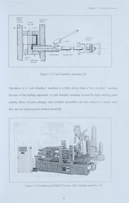
Figure 2.2 Cool chamber machine [8]
Operation of a "cold chamber" machine is a little slower than a "hot chamber" machine
because of the ladling operation. A cold chamber machine is used for high melting point
casting alloys because plunger and cylinder assemblies are less subject to attack since
they are not submerged in molten metal [8j.
Figure 2.3 Commercial High Pressure Die Casting machine /9/
Chapter 2. Literature Review
Figure 2.3 shows a commercial machine for HPDC process available in the market.
2.2
The Advantages of Die Casting Process
Die casting is an efficient, economical process offering a broader range of components
than any other manufacturing techniques [9].
i-Z W Z 0 0.. 2 0 0 cr:
w
a.. ;--t/l 0 U w>
l -<! _J W 0:: 104~---1(J110
210
1D·'
1/
PERMANEN
MOULD
LOW
PERI·'lA ,'J!:--n
,/ ~"l::)ULC
'PRESSURE
'-1::::---...;:N~---/·
[SM.J]
\SAND
10
"""---,
\
"'ell
'", LOW
PRESSLJRf
_ _ _ ... 1-::-_ I . ...I.-I ..,--____ L. _____ - '
10
210
310'
10
510°
[image:20.595.111.469.281.579.2]NUMBER OF COMPONENTS
Figure
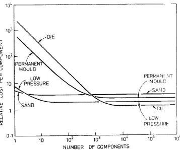
2.4 Process economic/or die casting [5}
Figure 2.4 shows a chart for economic selection of several casting process based on the
cost per component against the number of components.
It
has sho\\J1 that the
HPDC
process is the most economic process for high volume production (10
3and more).
Chapter 2. Literature Review
followed by low pressure, permanent mold and finally sand casting. Other advantages are
\51:
High-speed production
Die casting provides complex shapes within closer tolerances than many other mass
production processes. Little or no machining is required and thousands of identical
castings can be produced before additional tooling is required.
Dimensional accuracy and stability
Die casting produces parts. while maintaining close tolerances.
Sirengih and weighl
Die cast parts are stronger than plastic injection moldings of the same dimensions. Thin
wall casting is stronger than those possible with other casting methods. In addition.
because die casting is not consisted of separate parts welded or fastened together. the
strength is that of the alloy rather than the joining material.
Mulliplefinishing techniques
Die cast parts can be produced with small textured surfaces, and they are easily plated or
finished with a minimum surface preparation.
5iimplitied assemhly
Die castings provide integral fastening elements, as bosses and studs. Hoks can he cored
and made to tap drill sizes, or external treads can be cast.
Chapter 2. Litera/ure Review
2.3
Application of Die Casting
Each of the metal alloys available for die casting offers particular advantages to the
components. Therefore, the selection of materials for components varies depending on
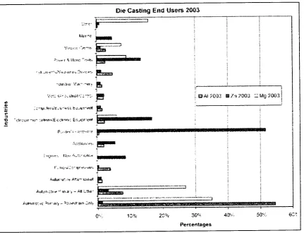
their function and properties of the components. Figure 2.5 shows the application of
several alloys in different industry.
Die Casting End Users 2003
t-""
"''')
~::r<'
-,.,.--->
I t..ler~~:, ) . - . :
~ .. r .. =;·~·;;: .-.('!-~;!. L~--
...
-J..
=-;·.\' ... ·r
~ Il;:n::·-.~"I:~ ~.~.iiiiiiiiiiiii
__
. :.1. _l1·~···~.;\/·~J-.U·-::·. ~·~.·I~ .. ~ ~
1
···..:u!...":, It;:· .... ~ .fl'· . :""el~.
I!L
1 , · ' · '
-:
\/.:"'.: 'S",'" :,,":.111';"'.';. --:':'
.
I!!
i.
IlJ AI :;003 III h ;,0003 :2 '-'1g :1003r .. ,·.j.·,, .::'::" .. "."
,"U---.... .::::h;:":r:.~
; ":':J11I~·. U:_'I~ ... ~::. I:..·tl·.~ .. _ _ _ _
1· ... -II:.. .. ..t·.:::·'I'·::~···'I·~ ~
..
Aulvl"u~ .'':-At:~h lC:It.t4
I!
.j
(; -:;:=1
Aut'':f.'':':''f'C''~: II\'!', u ,.:.n : .... 'j.:-.
.
Ms
T :,
AU"); ... ): ,'C :';IP'~"Ii-t - :'>;:'.'-«"it-aln ~:nl'r
i";' ...
~...
_~... ' .. .,... ... _
...
-F . . . . " ______ . . . : • • ~_ ... ' .... ~ ••• n::;:~::.:*
0'-.. :
[image:22.595.87.519.269.599.2]Percentages
Figure
2.5
Die casting end user 2003
[5
J
Some of the applications for these alloys are [5]:
Aluminum Die casting
***141
i !
,
i
.. .gas'
Aluminum is lightweight and while processed high dimensional stability of complex
shapes and thin walls can be achieved. Aluminum has good corrosion resistance and
Chapter 1. Literatllre Revie'W
mechanical properties, high thermal and electrical conductivity, as well as strength at high
temperature. Examples are the transmission housing in motor industries and the base for a
Teleprinter.
Zinc Die casting
Zinc is the easiest alloy to cast, it offers high ductability, high impact strength and
ISeasier platable. Zinc is economical for small parts and has a low melting temperature
which prolongs the die life; Examples are the toys, small size components and the
components that have a good surface finish such as chrome-plated.
Brass Die casting
This alloy possesses high hardness, high corrosion resistance and the highest mechanical
properties of alloy cast.
It
offers excellent wear resistance and dimensional stability. with
strength approaching that of a steel part; Example is the plumber hardware such as water
taps and shower mixer.
Magnesium Die casting
The easiest alloy to machine, magnesium has an excellent strength-to-weight ratio and is
the lightest alloy commonly die cast; Example is a mobile phone case.
2.4
Die Casting Defects
Die casting defects can be classified into external and internal defects. External Jdects
are normally related to surface defects which can be visually identified \\hereas the
internal defects are those defects that built internally and can be seen \\hen certain
operation has been carried out such as X-Ray, Ultra sound or any destructive process.
Chapter 2. Literature RevieJ.1"
![Figure 2.1 Hot chamber machine [8].](https://thumb-us.123doks.com/thumbv2/123dok_us/8786928.907380/17.595.126.478.457.647/figure-hot-chamber-machine.webp)