Reserh Report
DEVELOPMENT OF WOOD BASE MATERIAL FOR RAPID PROTOTYPING PROCESS
Short Term Grant Vot No:
0573
BY
Dr Md Saidin bin Wahab
FACULTY OF MECHANICAL AND MANUFACTURING ENGINEERING UNIVERSITI TUN HUSSEIN ONN MALAYSIA
ABSTRACT
This document presents initial development of wood-based composites with the
aim to develop an alternative material at low cost for rapid prototyping process. Powder
blends containing wood powder (90-120pm) with commercial ZP102 as a plaster
powder material from ZCorporation were mechanically blended to produce different
composition of (vol. %) 25:70, 5050 and 75:25 respectively. The blended material were successfully processed on
3D
printers (2406) which was used as a rapid prototypingmachine to produce three-dimensional components and followed by post-treatment with
ZMax solution to improve the mechanical properties. The mechanical properties,
dimensional accuracy and surface quality of the build components were evaluated and
the results were compared with the unfilled ZP102 material. The result shows that the
mechanical properties were improved with the increasing of wood powder content to 50
vol. %. However, dimensional accuracy and surface quality were decreased as the wood content increased. Further work on powder preparation is required in order to fully
CONTENTS
CHAPTER CONTENTS PAGE
I INTRODUCTION
1.1 Background of the problem
1.2 Objectives
1.3 Scopes of the Study
1.4 Important of the Study
1.5 Expected result
1 .6 Rationale
I1 LITERATURE REVIEW
2.1 Overview of Rapid Prototyping
2.2 Classification of RP System
2.3 Three Dimensional Printing (3DP)
2.3.1 The Basic Process of 3D Printing
2.3.2 Important Processing Parameter
2.3.3 Commercial 3D Printing
2.4 Material
2.5 Previous Studies by Student
METHODOLOGY
3.2 Raw Material
3.3 Parameter Setting
3.4 Powder Setting
3.5 Specimen Preparation
3.6 Product Analysis
3.7 Conclusion
IV RESULTS
4.1 Hardness Results
4.2 Dimensional Accuracy Results
4.3 Surface Roughness Results
4.4 Tensile Test Result
4.5 Product Appearance
V DISCUSSION
5.1 HardnessValue
5.2 Dimensional Accuracy
5.3 Surface Roughness
5.4 Tensile Test
5.5 Summary
CONCLUSION AND RECOMMENDATIONS
6.1 Conclusion 5 1
6.1.1 Mix Material between Wood Dust and
ZP 102 Based-Powders 52
6.1.2 Cost 52
6.2 Suggestion and Recommendation 5 2
Mixture
Preservation Time
Binder
Post Processing The Part
Infiltrating The Part
Improve Quality of Surface Finish
Treatment of Manufacturing Part
Hardness Equipment
CHAPTER I
INTRODUCTION
Rapid prototyping (RP) is a technology utilizing a layer by layer
manufacturing technique. The term "rapid prototyping" refers to a number of
different but related technologies that can be used for building very complex physical
models and prototype parts directly from 3D CAD model. This technology takes
information from a three-dimensional (3D) computer-aided design (CAD) database
and produces a solid model (prototype) of the design. Among these technologies are
three dimensional printing (3DP), stereolithography (SLA), fused deposition
modeling (FDM), laminated object manufacturing (LOM), selective laser sintering
(SLS) and inkjet-based systems. This technique provide alternative for producing
prototypes and functional models with complex geometry without the need of tooling
as compare to the conventional routes.
The Three-Dimensional Printing (3DP) process is a manufacturing
technology for the rapid and flexible production of prototypes, parts, and tooling
directly from a CAD model. It is an extremely flexible system, capable of creating
parts of any geometry and using any material including ceramics, metals, polymers,
and composites. This process is also capable of having local control over the
material composition, microstructure, and surface texture [I].
RP technologies gave significant contribution in the field of wood base
product base on wood dust. This material is considered as one of the optional
material for 3D printer. The main advantage of wood dust is can use waste material,
easy to find, and low cost.
In recent years, Three Dimensional Printing (3DP) came to the foreground as
a very competitive process in terms of cost and speed, and sales of related equipment
have increased significantly compared to other RP machine.
1.1 Background of the Problem
3D printer (3DP) is important in manufacturing process for fabricates models,
quickly print a prototype and show it to engineering, sales, and marketing groups as
well as to toolmakers.
Since this method become too important for manufacturing, faculty of
mechanical engineering at UTHM was provide a Z406D 3D printer for student to
make research. However, 3DP currently limited in the choice of materials and it is
involved high cost which is faculty needs to spend around RM3000 to buy the
material that use in the operation. So that, developing a new material like wood dust
can make the cost are less than before.
As we know, wood dust is waste material, so reusing waste product in 3D
printer is a better way to less cost of product and give more benefit to prevent
pollution and environment friendly.
1.2 Objectives
The objectives outlined from the current work are as below:
i. To research suitable type of wood base material for
RP
process.ii. To determine the properties of wood material for 3D printing in particular of
1.3 Scopes of the Study
The scopes outlined to achieve the objectives above are as follows:
i. Study the characteristic of different type of wood material which suitable for
rapid prototyping (RP) process.
. .
11. Prepare raw material for 3D printing process using recycle material from
wood.
iii. Fabrication of sample component using 3D printing process.
iv. Evaluate different post processing technique.
v. Analyze the quality of the fabricated of product on mechanical properties,
surface quality and dimensional accuracy.
1.4 Important of the Study
The propose study is to investigate the suitability of using wood base as a raw
material for 3D printing process.
1.5 Expected result
The purpose of this research is to develop a new raw material for RP process
using wood base material. Besides that, this study will determine suitable type of
wood base material for RP process and the properties of wood material for 3D
printing in particular of mechanical properties, surface quality and dimensional
1.6 Rationale
Nowadays, cost operations of the rapid prototyping are expensive. In this
study, it will using alternative material and can reduce operation cost. So, the
RP
system using this wood base material can be made at a low cost, the material are also
CHAPTER I1
LITERATURE REVIEW
2.1 Overview of Rapid Prototyping
Rapid Prototyping (RP) can be defined as a group of techniques used to
quickly fabricate a scale model of a part or assembly using three-dimensional
computer aided design (CAD) data. It is called rapid prototyping because it can
prototype parts very rapidly and a special class of machine technology that quickly
produces models and prototype parts from 3-D data using an additive approach to
form the physical models. The unique characteristic of RP is that it makes
prototypes one layer at a time or layer by layer.
2.2 Classification of RP System
Rapid prototyping systems can be classified in a variety of ways, depemding
on the physics of the process, the source of energy, type of material, size of
prototypes and the like. Accordingly, all RP system can be classified as liquid-base,
Fundamentally, the development of RP can be seen in four primary areas,
input, methods, materials and applications. There are many different ways of
[image:11.517.51.464.141.312.2]classifying RP systems according to the different methods used, as shown in Table
Table 2.1 : Classification of RP process by method [4]
Photupolymcrisa~on
Laser Droplet Adhaion
Lnser curing Masked lamp Sheet lamir~ation sintering d e p i t ~ o n bnnding
3D System's SLA Clubital's SGC Ilelisys* M M DThl's SLS Fmunhonep's B i 3 System's
MJS MJhI
Teijin Saki's K ~ ~ Z A ' S SAW Svatasys' FDM Soiige~~'h
Solif'orn~ DSPC
Mitsubjrhi'g SOUP Kinergy's Zippy MTqx 313
System Printing
EOS's Stereos System
Meiko's RP Spm
2.3 Three Dimensional Printing (3DP)
The three dimensional printing (3DP) based on MIT's (Massachusetts
Institute of Technology) ink jet technology and utilised by Z-Corporation in a variety
of printers is considered to be one of the most future oriented rapid prototyping (RP)
systems. It is classified as a typical "concept modeller", a low-end system, and
represents the fastest RP-process.
2.3.1 The Basic Process of 3 Dimensional Printing
The 3D Printer process uses ink-jet printing technology to build parts in
layers. A slicing algorithm draws detailed information of the layer from the CAD
model of the part. Each layer begins with a thin distribution of powdered material
material selectively joins the particles where the object is formed. A piston than
supports the powder bed and part-in-program, lowest the platform, deposits a fresh
layer of powder, and binds the powder again. This layer-by-layer process continues
until the part is completed.
During the build process, loose powder surrounding the bonded area serves as
the support material. The 3D Printer process is a powerful prototyping process
useful for the creation of functional parts and tooling directly from a CAD model.
w
+
1) Sl~read powcler 2) Pilllt layer 3) Piston lllove~llel~t
[image:12.515.49.455.234.486.2]3) I~lteimecliate stase 5 ) Last layer pi-hlted
Figure 2.1 : Schematic Illustration of Three Dimensional Printing Process
2.3.2 Important Processing Parameters
The quality of building parts and building performance of 3D Printer are
strongly related to its process parameters including binder setting saturation value
(shell & core), binde~setting saturation level, layer thickness, shrinkage, and location
Each process parameter may affect the quality of a RP part and the build
time. Unsuitable process parameters setting may make RP prototypes with poor
quality and may waste materials and building time. The manufacturing process
parameters of 2406 3D Printer system are illustrated as follows [ 5 ] :
i. Binder setting saturation value (shell & core): The building method of
the 2406 3D Printer system uses a powder bound with binder to shape
RP parts. From 2D sectional layers that are sliced by slicing algorithm
system software, each 2D section is composed of shells and cores. As
the setting value increases, the better the quality of the RP parts; however the binding time will be increased, too.
ii. Binder setting saturation level: Binder setting saturation level is the
thickness of infiltration, when the binder is filtering.
iii. Layer thickness: The process layer thickness means the height of the
powder bed that dropped down along Z-axis in processing. It can be
set within the range of 0.003" - 0.009" (or 0.0762mm to 0.2286 mm). If the layer setting is thinner, the quality of the RP parts will be finer; however the tradeoff is the building time will be increased.
iv. Shrinkage: 2406 3D Printer machine generally works at normal
atmospheric temperatures. Because the climate of each place of the
world is different, the powder will suffer from volume swell or
shrinkage by getting hot or cold and by getting wet or dry. It has
caused the RP parts quality to worsen.
v. Location of made-up parts: The working direction of the 2406 3D
Printer system's spray-nozzle is from right to left on the powder bed.
If the location of RP parts is put on the right side, the path of the
spray-nozzle may be shortened; thus decreasing the part building
2.3.3 Commercial 3D Printing Process
a. 2406 System
The 2406 System is the concept modeling solution for leading companies and
universities. The 2406 System is a premium 3D Printer with the capability of
printing in full-color, communicating important information about parts, including
engineering data, labeling, highlighting and appearance simulation. The system is
fast, convenient and easy to operate, allow accelerating the design process and
getting the products to market ahead of the competition.
The 2406 3D Printer offers a variety of materials. There are two materials
used with 2406 machine; the plaster based powder and the starch based powder. The
plaster based powder deliver high strength and detail. The starch-based powder
delivers in high speed at a very low cost.. Features of the 2406 System are as
[image:14.521.59.461.396.702.2]follows:
Table 2.2: Detail for 2406 System [2]
1
Build Speed1
Color mode: 2 layers per minuteI
Feature
I
I
Monochrome mode: 6 layers per minute1
Detail
Build Volume
I
I
0.003"-0.010" (.076-,254 mm)I
8" x 10" x 8" (203 x 254 x 203 mm)
Layer Thickness User-selectable at the time of printing:
I
Equipment Dimensions
I
40" x31" x44" (102 x 79 x 112 cm)I
Color RGB Full Color (Millions of Colors)
I
I
I
PLY, VRML (WRL) and SFX file formats/
Equipment Weight
System Software
as input. System Software runs on
Microsoft Windows* 2000
and NT.
470 lbs. (210 kg)
Z Corporation's proprietary System
b. How The 2406 System Works?
Firstly, the 2406 machine must be checked and made ready before any part
can be printed. The feed piston should have sufficient powder, and the build area
needs to be scraped by the wiper blade until it is level with the powder. All
instructions regarding the safe and efficient use of the 2406 system should be known
for the optimum performance of the system.
Before the printing of any part, the 2406 system software imports the STL
file and slices it into hundreds of 2D cross sections of certain slice thickness. To
print a part, the following steps are taken:
1 . The machine spreads a layer of powder from the source piston
to cover the surface of the build piston.
2. The machine than print binder solution onto the loose powder,
forming the first cross section where the binder is applied, and
the powder is glued together. The remaining powder remains
loose and supports the layers that will be printed above.
When a cross section is complete, the build piston is lowered
slightly, a new layer of powder is spread over its surface and
the process repeated.
The parts grow layer by layer on the build piston until the part
is complete while it remains surrounded and covered by loose
powder. Finally the build piston is raised and the loose
Sfap 5' Feed P~ston Up Build Prston Ouwir
(Ropeot Sbps 1 5 Unlit EaM IS Com@Je)
Step 6. Bu~d Complete Step 7. Penmve Excess Powder
[image:16.524.82.410.60.394.2]- -
Figure 2.2 : The Printing Process [2]
c. Advantages of a 2406 System
The 2406 System builds speed and efficiency into the design process and
the highest quality into the products. The printers are professional, complete
physical modeling solutions delivering hll-color communication. Other
1. Speed
Each layer is printed in seconds, reducing the time it takes to
print a hand-held part to 1-2 hours.
. .
11. Color
The 2406 System can create parts fiom a full 24-bit palette of
colors, resulting in multiple color prototypes. Color can be used to
communicate important information including engineering data,
labeling, and highlighting and appearance simulation.
iii. Simplicity
The 2406 System is straightforward to operate, eliminating the
need for a designated technician. The 2406 System is based on
standard, off the shelf components developed for the ink jet printer
industry resulting in a reliable, dependable 3D Printer.
iv. Versatility
Companies are using 2406 System parts in every step of the
design process for communication, design review and functional
testing. The option of infiltrating parts offers customers the
opportunity to produce parts with a variety of material properties to
serve a range of modeling needs.
2.4 Material
3D printers have the widest range of material, as a large number of binder-
need to contain more material than is necessary for the model, depending on the size
of the build chamber.
1. Plaster Material System
The plaster material system has been found to remain
dimensionally accurate during printing and thus, the
recommended anisotropic scaling values are one (1) in all axes. If
the infiltrant system being used changes the accuracy of the part,
the values must alter as needed. The shell and core saturation
values for the plaster material system are generally constant
values, meaning that there is only one value for all geometry
types.
.
.
11. Starch Material System
The shrinkage found in the starch material system is proportional
to the part geometry and the drying time of the part. The longer
the part is left to dry, the larger the shrinkage value. The part is
most stable in the X and Y axis and shrinks more in the Z axis. Thus, the anisotropic scaling factor of the Z axis will always be
greater than the values for both the X and Y axis. The shell and
core saturation values for the starch material system depend on
part geometry. A thick walled part will have lower shell
saturation than a thin walled part. Core saturation is dependent on
the wall thickness of the part. The thinner the wall thickness the
higher the core saturation; the thicker the wall thickness the lower
the core saturation. The ZPrint Software will recommend shell and
core saturation values based on the part geometry. If parts come
out weak, increase the saturation values by 10%; if parts are
iii. ZCast Material System
The ZCast material system has been found to remain
dimensionally accurate during printing and thus, the anisotropic
scaling values are one (1) in all axes. The shell and core
saturation values for the ZCast material system are generally
constant values, meaning that there is only one value for all
[image:19.526.161.370.231.401.2]geometry types.
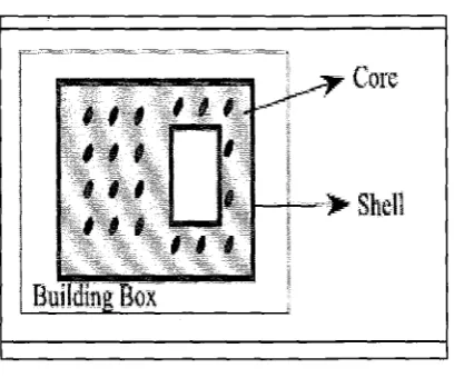
Figure 2.3: Definition of shell and core. The dark areas around the
boundary of each layer of a 3DP built part are the shells. The inside area
with light color of each layer of a 3D Printer built part is the core.
2.5 Previous Studies by Students
i. Development of an Optional material for 3D Printer by Using Aluminium
Powder (Wilson Tay, 2007)
Studied have been focused on the effects of process parameter including layer
thickness, ratio Aluminium powder versus ZP102 plaster based powder, and binder
setting saturation value (shell and core) on the machining characteristic including
accuracy dimension, surface roughness, and the hardness for the part that build by
ratio Aluminium powder versus ZP102 plaster based powder 1 :3 achieved best
accuracy dimensional and 1 :4 achieved best surface finish and hardness value in the
ratio 1:3, 1:4 and 1:s. In this researched, part 100% Aluminium powder build with
Binder Zb56 was very brittle and not suitable to do the testing.
ii. Developing New Material for 3D Printing by Using A Rice Flour (Mohd
Syahril Mohd Sumery, 2007).
The main interest of this research is to study the effect of the machining
process parameter include layer thickness, ratio of mixing and saturation value-core
and shell on the model characteristic including surface roughness, dimensional
accuracy and flexural strength. An implementation of Design of Experiment (DOE)
will be done by using Taghuchi Method, Qualitek-4 software to obtain the parameter
contribute and optimum parameter setting for the best building of models. Based on
the result gain fiom the experiment, part build from ZP 102 plaster-based powder
give better quality in most of the machining characteristic compare to the part build
from RF starch-based powders. Based on the result gain from the experiment, part
build from ZP 102 plaster-based powder give better quality in most of the machining
CHAPTER I11
METHODOLOGY
This chapter addresses the research methodology, experiment and test
involved in this research work. The earlier topic explains in general the research
methodology. Further on, this chapter describes the rationale on the material,
parameters and level selection. The methodology and procedures is important to
determine the flow, direction and method to work in this research study. With
list down all the element of the procedures and method of the project progress,
the specific plan are clarify.
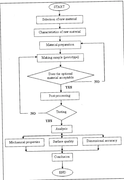
3.1 Research methodology
In this research work the methodology is divided into several stages as
shown in Figure 3.1 The methodology of previous research consists of several
Selection of raw material
J
Characteristics of raw material
f
+
Material preparation
Does the optional material acceptable
c N O
I
YES
Analysis
f - l
[image:22.517.70.472.51.634.2]3.2 Raw Material
Before experiments were starting, material needs to prepare. It's
important to make sure the material characteristic suitable for 2406 3DP
1. Powder preparation
In this study, the materials will be use in ZP 102 plasters based powder
and wood dust based powder. Particle size of wood dust using in this study still
in research and the particle size of
ZP
102 plasters based powder is between50-250pm.
As an initial, a pure of wood dust will be use and analysis will be run to
the finishing product. As the result that can be predicted, a certain change of the
percentage of composition will be considered to the powders. The mixture
powders that will be use together is ZP 102 plaster base that was provide by the
manufacturer.
The wood dust is can be found from Sindora Timber Sdn. Bhd. located at
Bandar Tenggara. In this study, wood dust is used as a powder for material
preparation. Figure 3.2 shows the wood dust is looks like which are having rough
surface and large in particle size. The wood dust needs to sieve to get the
Figure 3.2: Bottom wood dust
Scanning electron microscope (SEM) model Jeol JFM-6380 LA is a
microscope that uses electrons rather than light to form an image which is can be
found in the Science Material Laboratory at UTHM. It will used in this research
to measure the microstructure composition of
ZP
102 plaster based powder andwood dust. Microstructure composition of the both materials will be comparing
and this data will be use in data analysis.
[image:24.532.111.427.448.671.2]3.3 Parameter Setting
In this experiment, the process parameters including layer thickness,
saturation value (shell), saturation value (core), location make-up part and ratio
wood dust based powder with ZP102 plaster based powder. Table 3.1 shows the
[image:25.525.104.466.211.451.2]setting condition.
Table 3.1 : Recommended Parameter from Corp. Inc.
3.4 Powder Setting
i. Anisotropic Scaling Value
Anisotropic scaling values scale the model to accommodate any
shrinkage or expansion of the part either due to characteristic of the material
system or infiltrate system. The plaster material system has been found to
remain dimensionally accurate during printing an thus, the recommended
.
.
11. Saturation Value
The saturation value determine how much binder is placed on the powder
to print the part and the part is made up two areas, the shell and the core. The
shell and core saturation values for the plaster material system are generally
constant values, meaning that there is only one value for all geometry type.
. .
.
111. Powder preparation
Before experiments were starting, material needs to prepare. It's
important to make sure the material characteristic suitable for 2406 3DP. In this
study, the materials will be use is ZP 102 plaster based powders and wood dust
based powder. ZP 102 powder is one of the plaster based material being used
[image:26.533.133.467.443.554.2]now for 2406 3D printer.
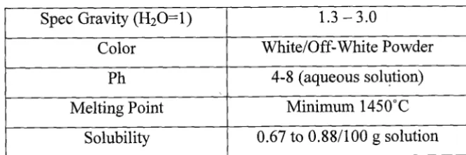
Table 3.2 : Physical and Chemical Properties of ZP102 Plaster Based
Powder
Microstructure composition of ZP 102 plaster based powder and wood
dust will measure by using scanning electron microscope (SEM). Microstructure
composition of these materials will be comparing. These data will be used in
data analysis. Because the materials are non-conductive specimens, this material
will be coated with a thin layer of platinum before measurement are doing by
using SEM.
Spec Gravity (H20=1)
Color
Ph
Melting Point
Solubility
1.3 -3.0
White/Off- White Powder
4-8 (aqueous solution)
Minimum 1450°C
iv. Binder Preparation
Zb56 binder was selected in this study. This binder is suitable for powder
based materials. But if the binder is not adhesive with the wood dust, it will
change with the suitable binder.
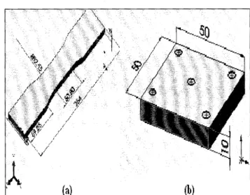
3.5 Specimen Preparation
Based on the test conducted, there will be only one drawing using Solid
Work software to fabricate specimen by using 3D printer. The Solid Work
software is in STL. This specimen will be use to measure the value of surface
roughness and flexure strength (three point bending test) value. The dimension
[image:27.525.87.445.380.659.2]of test specimen based on the ASTM E l 8 standard as figure below.
In this process part from the 3D printer will be carry out to process for the
next process. This includes depowdering, drying and infiltrate the part.
i. Removing the finishing part
The part will be removing from the build box after the building is
complete as follow:
Powder-based parts: wait approximately 10 to 15 minutes to ensure that the
uppermost layer of the part have had a chance to dry. Plaster-based parts:
leave the part in the bed for approximately 30 to 60 minutes. Zcast parts:
same period as plaster-based parts.
The machine should turn off by pressing the online button.
Lift the top cover.
Vacuum off any powders on the deck.
Press the Feed Down button to lower the feed piston.
Place a tray on the top of the Feed area.
Take a moment to look at the computer screen and determine exactly where
parts lie in the build box.
Without raising the build piston, begin vacuuming powder out of the box.
Vacuum powder away from the buried parts, and clean powder out of the
margins against the wall of the Build Box
Raise the Build Piston by holding down the Build Up button to gain access
to the sides of the parts.
The part and place on the tray will remove. The part is now ready to be
. .
11. Depowdering the part
The purpose of this process is to clean up the parts from the existing
powders by using a depowdering unit. The steps to do this process are given as
below:
a. Place parts inside the depowdering unit.
b.
Using the compressed air system included in the Depowdering Station,remove any excess powder that remains in any concave surface. The air
pressure in the Depowdering Station is adjustable. For bulky parts, turn
the air pressure up and fro delicate parts, turn the air pressure down.
iii. Drying the part
To infiltrate starch or plaster parts with wax, the part must be hot and dry.
The part will be preheated at 165 degrees Fahrenheit in the Automated Waxer or
in the drying oven and the drying time are regarding to the part thickness. The
[image:29.526.126.394.533.670.2]related between the time and wall thickness show in chart below.
Table 3.3: The related between time and wall thickness of the part
Average WaI I Sh irzkness Brying Time
I/$ inch 15 minutes
11.4 inch 30 rninutes
l(2 inch 45 minutes
iv. Infiltrating the part
The infiltrate processes are important to produce extra and variable
material properties to the finishing parts. But for as an early stage design tool, it
may not be necessary to infiltrate the parts at all. For this stage, infiltration must
use a resin that recommended by the manufacturer,
Z
Corp company which isCyanoacrylate 502. The step to infiltrate the part a given as below.
a. Read and understanding the Safety Information on the resin container label.
b. Dry the part in the Automated Waxer or dry drying oven
c. Then place the part on the waxed paper or on the non- stick surface.
d. Apply a thin coat of resin to the entire part by gently squeezing the bottle and
letting the resin drip onto the part.
e. Once the entire part is coated, let it dry for 45 minutes to 1 hour. To stop the
part from sticking to the wax paper, pick it up and move it every 10 minutes
until dry.
f. Once the part is dry, it can be sanded to improve the surface finish.
g. To further improve the surface finish, the part can be waxed.
To
wax a part infiltrated with resin, the part must be heated at 165 degree Fahrenheit for 1to 3 minutes before waxing.
3.6 Product Analysis
An analysis will be conduct to the finish product to perform the necessary
condition. During this analysis, some of the criteria will be judge like
microstructural characteristic and particle size, dimension accuracy, surface
References
[I] Kenneth G. Cooper, "Rapid prototyping technology : selection and application", New York, Marcel Dekker, 2001
[2] Frank W. Liou, "Rapid Prototyping And Engineering Applications: A Toolbox for Prototype Development", Florida, CRC, 2008
[3] D.T Pham et al, "A comparison of rapid prototyping technologies", International Journal of Machine Tools and Manufacture, Volume 38, Issues 10-1 1, October 1998, Pages 1257-1287.
[4] Alain Bernard et al, "New Trends in Rapid Product Development", CIRP Annals
-
Manufacturing Technology, Volume 51, Issue 2, 2002, Pages 635-652
[5] R.I. Campbell et al, "Surface roughness visualisation for rapid prototyping
models", Computer-Aided Design, Volume 34, Issue 10, 1 September 2002, Pages 71 7-725
[6] Adriano P. Nyaluke, "Rapid prototyping: Applications in academic institutions and industry" Computers & Industrial Engineering, Volume 29, Issues 1-4, September 1995, Pages 345-349.
[7] E.A. Gruber et al, "The use of rapid prototyped 3D models for establishing dental occlusion in complex fiacture cases", British Journal of Oral and Maxillofacial Surgery, Volume 50, Supplement 1, June 20 12, Page S8.
[8] Y .G. Im et al, "Functional prototype development of multi-layer board (MLB) using rapid prototyping technology", Journal of Materials Processing Technology, Volumes 187-1 88, 12 June 2007, Pages 619-622
[9] Huiling Li et a1 "A study on embedded resistor components fabricated by laser micro-cladding and rapid prototype", Materials Science and Engineering: B,
Volume 133, Issues 1-3,25 August 2006, Pages 84-90.
[I 01 P Dunne et al, "Some demands on rapid prototypes used as master patterns in rapid tooling for injection moulding" Journal of Materials Processing Technology, Volume 150, Issue 3,20 July 2004, Pages 201-207.
[I 11 L.E. Murr, "Microstructures and mechanical properties of electron beam-rapid manufactured T i 4 A 1 4 V biomedical prototypes compared to wrought Ti4A1- 4V", Materials Characterization, Volume 60, Issue 2, February 2009, Pages 96-
105
[12] Liu Hongjun et al, "A note on rapid manufacturing process of metallic parts based on SLS plastic prototype", Journal of Materials Processing Technology, Volume
142, Issue 3, 10 December 2003, Pages 710-713,
[I41 C.S. Lee et al, "Measurement of anisotropic compressive strength of rapid prototyping parts", Journal of Materials Processing Technology, Volumes 187- 188, 12 June 2007, Pages 627-630.
![Table 2.1 : Classification of RP process by method [4]](https://thumb-us.123doks.com/thumbv2/123dok_us/8781788.904622/11.517.51.464.141.312/table-classification-rp-process-method.webp)

![Table 2.2: Detail for 2406 System [2]](https://thumb-us.123doks.com/thumbv2/123dok_us/8781788.904622/14.521.59.461.396.702/table-detail-for-system.webp)
![Figure 2.2 : The Printing Process [2]](https://thumb-us.123doks.com/thumbv2/123dok_us/8781788.904622/16.524.82.410.60.394/figure-the-printing-process.webp)