International Journal of Emerging Technology and Advanced Engineering
Website: www.ijetae.com (ISSN 2250-2459,ISO 9001:2008 Certified Journal, Volume 3, Issue 11, November 2013)
421
Rectangular Microstrip Patch Antenna Design At 3 GHz
Using Probe Feed.
Pallavi Singhal
1, Kuldeep Jaimini
2Dept. of ECE , Krishna Institute of Engineering and Technology, Ghaziabad.
Abstract- In this paper, a microstrip patch antenna is studied and the results are simulated using IE3D simulator with an operating frequency of 3 GHz. The conducting patch can take any shape but the preferred configurations are rectangular and circular since the other configurations are parameters. IE3D is a Moment of Method Simulator which solves the Maxwell’s Equations in an integral form through the use of Green's functions. The results are analyzed and discussed in terms of return loss, bandwidth, 3D and 2D radiation pattern, Gain vs. frequency plot. The return loss of this antenna is -26dB at 3GHz. The proposed antenna offers 2.34% bandwidth at 2.95- 3.02 GHz. In designing a rectangular patch antenna, selection of patch width, length and dielectric constant are the major critical parameters.
Keywords- Coaxial Probe Feed, Green’s function, IE3D Simulator, Method of Moment, Radiation Pattern, Rectangular Patch antenna, Return Loss.
I. INTRODUCTION
In today’s modern communication industry, antennas are the most important components required to create a communication link. Microstrip antennas have found applications in high performance aircraft, spacecraft, satellite and missiles; where size, weight, cost, performance, ease of installation and aerodynamic profiles are important [1]. The microstrip antenna radiates a relatively broad beam broadside to the plane of the substrate. Thus the microstrip antenna has a very low profile, and can be fabricated using printed circuit (photolithographic) techniques [2]. This implies that the antenna can be made conformable, and potentially at low cost. Other advantages include easy fabrication into linear or planar arrays, and easy integration with microwave integrated circuits, mechanically robust when mounted on rigid surfaces, compatible with MIMC design and when the particular patch shape and size are selected; they are very versatile in terms of resonant frequency, polarization, pattern and impedance. Initially microstrip antennas were received by the antenna designers with caution due to its narrow bandwidth which reduced the number of its possible applications [3-4]. Development during the 1970s was accelerated by substrates with attractive properties, improved photolithographic techniques & better theoretical models. Since then extensive research & development of microstrip antennas & arrays was done in the 70s & 80s, aimed at exploiting their numerous advantages.
Development also furthered with the advent of better analytical techniques & models that were able to predict the pattern in finer detail & characteristics like resonant frequency & input impedance with greater accuracy [5]. Recent system demands have become a dominant factor in directing the development of microstrip antennas. Communication systems with their ever wider bandwidths have led to research being done to increase the bandwidth of microstrip antennas. Need for aerodynamic antennas in the field of aviation & defence areas such as missile development have given impetus to the development of conformal microstrip antennas & their arrays. In this paper, we have design a rectangular patch antenna at an operating frequency of 3 GHz and results are simulated using IE3D simulator. IE3D allows us to display the 3D patterns, 2D patterns, merge different patterns, find array radiation patterns, and find the transfer functions between the transmitting (Tx)
antenna and the receiving (Rx) antenna. We can also display and process the parameters of linearly polarized and circularly polarized antennas.
II.STRUCTURE OF MICROSTRIP PATCH ANTENNA
International Journal of Emerging Technology and Advanced Engineering
Website: www.ijetae.com (ISSN 2250-2459,ISO 9001:2008 Certified Journal, Volume 3, Issue 11, November 2013)
[image:2.595.63.266.136.254.2]422
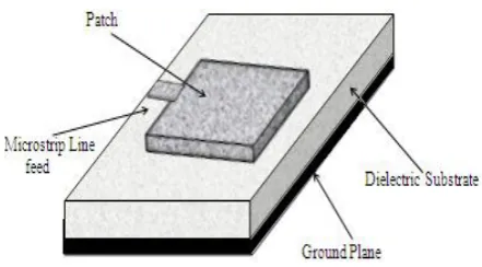
Fig.1 Microstrip Patch Antenna Top View.
III. DESIGN PARAMETERS
The microstrip patch has been designed for the S-band frequency ranges (3GHz in this case). Microstrip patch antenna working on this frequency range finds application in weather radar, surface ship radar, and some communications satellites. The design flow for the single patch dimensions, using the cavity model approach is as follows:
Fr, frequency of operation = 3 GHz
Err, relative permittivity of substrate material= 2.32 h, height of substrate = 0.159 cm
Calculated length and width of patch are: L, length of patch = 3.2 cm
W, width of patch = 3.8 cm
The dominant mode is thus TM01. The results have been
obtained using IE3D Simulator.
IV. FEEDING TECHNIQUES
Microstrip patch antennas can be fed by a variety of methods. These methods can be classified into two categories: contacting and non-contacting.
1) In the contacting method, the RF power is fed directly to the radiating patch using a connecting element such as a microstrip line.
2) In the non-contacting scheme, electromagnetic field coupling is done to transfer power between the microstrip line and the radiating patch.
Fig. 2 Feeding Techniques
A. Coaxial Probe
[image:2.595.348.513.341.451.2]Feed-In this paper, rectangular patch antenna is fed by coaxial probe. The Coaxial feed or probe feed is a very common technique used for feeding Microstrip patch antennas. As seen from Fig. 3, the inner conductor of the coaxial connector extends through the dielectric and is soldered to the radiating patch, while the outer conductor is connected to the ground plane. The main advantage of this type of feeding scheme is that the feed can be placed at any desired location inside the patch in order to match with its input impedance. This feed method is easy to fabricate and has low spurious radiation. However, a major disadvantage is that it provides narrow bandwidth and is difficult to model since a hole has to be drilled in the substrate and the connector protrudes outside the ground plane, thus not making it completely planar for thick substrates.
Fig. 3 Coaxial Feed Technique
B. Microstrip Line Feed-
In this type of feed technique, a conducting strip is connected directly to the edge of the Microstrip patch as shown in Fig. 4.
Fig. 4 Microstrip Line Feed Technique
[image:2.595.320.541.525.647.2] [image:2.595.51.280.548.746.2]International Journal of Emerging Technology and Advanced Engineering
Website: www.ijetae.com (ISSN 2250-2459,ISO 9001:2008 Certified Journal, Volume 3, Issue 11, November 2013)
423
C. Aperture Coupled Feed-
[image:3.595.55.271.240.372.2]In recent years a variety of non contacting feeds have been developed for microstrip antennas. In Aperture Coupled Feed technique [9], the radiating patch and the microstrip feed line are separated by the ground plane as shown in Fig. 5. Coupling between the patch and the feed line is made through a slot or an aperture in the ground plane.
Fig. 5 Aperture Coupled Feed
This arrangement allows a thin, high dielectric constant substrate to be used for the feed, and a thick, low dielectric constant substrate for the antenna element, thus allowing independent optimization of both the feed and the radiation functions. In addition, the ground plane eliminates spurious radiation from the feed from interfering with the antenna pattern or polarization purity.
D. Proximity Coupled
Feed-This type of feed technique is also called as the electromagnetic coupling scheme. As shown in Fig. 6, two dielectric substrates are used such that the feed line is between the two substrates and the radiating patch is on top of the upper substrate.
Fig. 6 Proximity Coupled Feed
Proximity coupling has the advantage of allowing the patch to exist on a relatively thick substrate, for improved bandwidth, while the feed line sees an effectively thinner substrate, which reduces the spurious radiation and coupling.
V. RESULTS AND DISCUSSIONS
[image:3.595.337.529.365.502.2]IE3D has been a full-wave EM simulator capable of modelling planar and 3D metallic structures in layered dielectrics. IE3D solves the Maxwell’s Equations in an integral form through the use of Green's functions. It allows us to display the “True 3D” Radiation Pattern and “Mapped 3D” Radiation Pattern of a pattern file in the list at a selected frequency. Here the operating frequency is 3 GHz. We can also display the 2D pattern in “Polar Plot” and “Cartesian Plot”. The “Polar Plot” is a cut on the “True 3D” pattern while the “Cartesian Plot” is a cut on the “Mapped 3D” pattern. The “theta” and “phi” in the “True 3D” pattern correspond to the same “theta” and “phi” in the antenna coordinate system. For the “Mapped 3D” pattern, the “phi” corresponds to the same “phi” in the antenna coordinate system while the “rho” in the “Mapped 3D” pattern corresponds to the “theta” in the antenna coordinate system. Directivity (dBi) is obtained as 6.50518 and gain (dB) is 8.542 dB.
Fig. 7 “ Mapped 3D” Radiation Pattern at 3GHz.
[image:3.595.337.527.524.667.2] [image:3.595.59.269.555.688.2]International Journal of Emerging Technology and Advanced Engineering
Website: www.ijetae.com (ISSN 2250-2459,ISO 9001:2008 Certified Journal, Volume 3, Issue 11, November 2013)
[image:4.595.66.261.141.278.2]424
[image:4.595.336.531.221.354.2]Fig. 9 2D Radiation Pattern( Castesian Plot) at 3GHz.
Fig. 10 2D Radiation Pattern( Polar Plot) at 3GHz
Fig. 11 Return loss characteristics of a rectangular patch antenna,L=32mm,W= 38mm, er= 2.32, h= 1.59mm.
Fig. 11 shows the best value of return loss after optimization which is about -26 dB. Scattering Parameter is a complex no. that has magnitude and phase angle. When magnitude of S11 is expressed in dB, it is known as
return loss at the input and it is always in decibels.
The value of return loss should be minimum in order to minimize the reflection wave and able to maximize the transmitting power thus operating the antenna with the better performance. This graph also represents the bandwidth of the antenna which is about 2.34% in this case.
[image:4.595.63.238.287.462.2]Fig. 12 Total Field Gain vs. Frequency Plot
Fig. 12 Shows the Total Field Gain vs. Frequency Plot at 3GHz. Simulated results show that directivity Gain is 6.4812 dBi which is a good agreement between the measured and simulated results.
V. CONCLUSION
The designed microstrip rectangular patch antenna efficiently resonates at 3GHz and gives good return loss of -26 dB with an impedance matching at 50 GHz. A good agreement is obtained between the measured and simulated results. This antenna can be easily fabricated on substrate material due to its small size and thickness. The simple feeding technique used for the design of this antenna make this antenna a good choice in many communication systems. Microstrip patch antenna working on this frequency range finds application in weather radar, surface ship radar, and some communications satellites.
REFERENCES
[1 ] Balanis, C.A. “Antenna Theory Analysis and Design”.3rd Edition.
New Jersey: john Wiley and, Sons, 2005.
[2 ] Kin-Lu Wong, “Design of Non-planar Microstrip Antennas and Transmission Lines,” John Wiley & Sons, Inc., 1999.
[3 ] G. A. Deschamps, “Microstrip microwave Antennas,” presented at the Third USAF Symp. On Antennas, 1953.
[4 ] H. Gutton and G. Baissinot, “Flat aerial for ultra high frequencies,” French Patent no. 703 113, 1955.
[5 ] Ramesh Garg, Prakash Bhartia, Inder Bahl, Apisak Ittipiboon, “Microstrip Antenna Design Handbook, Artech House, 2000. [6 ] J. R James and P. S Hall, “Handbook of Microstrip Antennas,”
[image:4.595.75.249.493.654.2]International Journal of Emerging Technology and Advanced Engineering
Website: www.ijetae.com (ISSN 2250-2459,ISO 9001:2008 Certified Journal, Volume 3, Issue 11, November 2013)
425
[7 ] R. Q. Lee, K. F. Lee, and J. Bobinchak, “Characteristics of a two-layer electromagnetically coupled rectangular patch antenna,” Electron. Lett. vol. 23, pp. 1070-1072, Sept. 1987.
[8 ] C. H. Tsao, Y. M. Hwang, F. Kilburg, and F.Dietrich, “Aperture-coupled patch antennas with Wide bandwidth and dual polarization Capabilities,” IEEE Antennas and propagation Symp. Dig., pp. 936-939, 1988.
[9 ] I. J. Bahl and P. Bhartia, “Microstrip Antennas,” Artech House, Dedham, MA, 1980.
[10 ]D. H. Schaubert, D. M. Pozar and A. Adrian, “Effect of microstrip antenna substrate thickness and permittivity: Comparison of theories and experiment,” IEEE Trans. Antennas Propagat., vol. 37, pp. 677-682, June 1989.