The Use of Generalized Beam Theory, Finite
Elements and Experimental Testing to Investigate the
Stability of Light Gauge Steel Sections Subject to Axial
Load
By: Jawad Abd Matooq
Supervised by:
Dr. Lawrence Weekes (Supervisor)
Dr. Philp Leech (Co-supervisor)
Directorate of Civil Engineering
School of Computing, Science and Engineering,
University of Salford
UK
Submitted in partial fulfilment of the requirements of
I
The aim of the project is to study and investigate the buckling behaviour of unbranched open cold-formed steel sections. First the advantages and disadvantages of cold-formed steel when compared to hot-rolled steel are demonstrated. Thin-wall steel members have lower stiffness which may lead to increased instability and buckling issues for this kind of member. Buckling issues such as Euler buckling, buckling load factors, linear and non-linear analysis, buckling modes (global, distortional and local buckling) and buckling analysis methods (finite element method, finite strip method and generalized beam theory) are addressed. The literature review is concerned with computer software applications, theoretical analyses and experimental tests which can predict buckling loads and related mode shapes for light gauge steel sections. The study focuses on the Generalized Beam Theory (GBT) using the Finite Difference method for solution with a view to developing models using MATLAB to predict buckling loads, buckling mode shapes and non-linear yielding loads of members subjected to axial load for different boundary conditions. Some applications (beam subjected to concentrated load), linear analysis of buckling problems (Eigen value problems) and non-linear analysis (Imperfect Problems) have been addressed. Also, the finite element method (ANSYS) was used to predict the linear eigen-buckling loads and related mode shapes, and the non-linear material and geometric analyses with the post-buckling and initial imperfection effects were addressed. Finally, for validation purposes, a set of 36 cold-formed steel samples (lipped C-section and
II
Abstract ... I List of Content ... II List of Figures ... X List of Tables... XXIII Acknowledgements ... XXIV Dedication ... XXV Declaration ... XXVI
CHAPTER ONE INTRODUCTION ...
1.1 General ... 1
1.2 Manufacturing methods of cold-formed steel ... 1
1.2.1 Cold roll forming machines ... 1
1.2.2 Press braking ... 2
1.3 Buckling terminology ... 4
1.3.1 Euler buckling ... 5
1.3.2 Buckling load factor ... 5
1.4 Buckling analysis ... 6
1.4.1 Linear buckling analysis (eigenvalue problem) ... 6
1.4.2 Nonlinear analysis ... 9
1.5 Buckling analysis methods ... 9
1.6 Aims and objectives ... 10
1.7 Contents of the thesis ... 11
CHAPTER TWO LITERATURE REVIEW ... 2.1 Buckling modes ... 13
2.1.1 Local buckling ... 13
2.1.2 Distortional buckling ... 14
2.1.3 Lateral distortional buckling ... 15
III
2.2 Experimental investigations ... 17
2.3 Theoretical investigations ... 27
2.3.1 Generalized beam theory (GBT) ... 28
2.3.1.1 GBTUL program ... 29
2.3.2 Finite element method (FEM) ... 34
2.3.3 Finite strip method ... 41
2.3.3.1 CUFSM program ... 41
2.3.3.2 Direct strength method (DSM) ... 43
2.4 Literature review summary ... 45
CHAPTER THREE FORMULATION OF THE GENERALIZED BEAM THEORY ... 3.1 Introduction ... 47
3.2 Rigid body modes ... 47
3.3 Higher order distortional and local modes ... 48
3.4 First order generalized beam theory ... 51
3.4.1 Displacement functions ... 53
3.4.1.1 Relationship between nodal displacements wi and ui ... 54
3.4.1.2 Relationship between nodal displacements vi and ui ... 55
3.4.2 Derivation of plate displacements up(i) and vp(i) ... 56
3.4.3 Derivation of plate displacements wp (i) and vp(i) ... 57
3.5 Basic equation of first order generalized beam theory ... 57
3.5.1 Strain displacement relationships ... 58
3.5.2 Stress-strain relationships ... 59
3.6 Virtual work of transverse bending moments ... 59
3.7 Virtual work of longitudinal membrane stresses ... 60
3.8 Formulation of the eigenvector problem ... 60
3.9 Equilibrium of externally applied loads ... 62
IV
3.12 First order GBT section properties evaluation ... 65
3.12.1 Evaluation of (C1jk) ... 65
3.12.2 Evaluation of (Bjk) ... 66
3.12.3 Evaluation of (D1 jk) ... 67
3.13 Basic equation of second order generalized beam theory ... 67
3.13.1 Strain displacement relationships ... 67
3.13.1.1 Membrane strains ... 67
3.13.1.2 Bending strains ... 68
3.13.2 Stress-strain relationship in presence of poisson’s ratio ... 68
3.13.3 Virtual work of transverse bending moment ... 69
3.13.4 Virtual work of longitudinal membrane stress ... 70
3.13.5 Virtual work of longitudinal bending stress ... 71
3.13.6 Virtual work of shear stain ... 72
3.13.7 Virtual work of membrane shear strain ... 72
3.14 Virtual work of membrane shear strain ... 75
3.15 Virtual work of the external loads ... 76
3.16 Second order equation of equilibrium ... 77
CHAPTER FOUR APPLICATIONS OF GENERALIZED BEAM THEORY ... 4.1 Introduction ... 78
4.2 Finite difference analysis of generalized beam theory ... 78
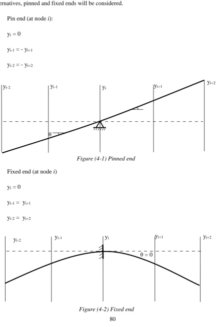
4.2.1 Boundary conditions ... 80
4.3 Linear problem using the generalized beam theory (beam subjected to axial load) . 81 4.3.1 Equivalent axial loading ... 82
4.3.2 Example... 83
4.4 Buckling problems using generalized beam theory ... 89
4.4.1 Linear analysis of buckling problems (eigen value problems) ... 90
V
4.4.2.1 Example... 106
CHAPTER FIVE FINITE ELEMENT ANALYSIS ... 5.1 Element type... 109
5.2 Material properties ... 110
5.2.1 Linear material properties ... 110
5.2.2 Nonlinear material properties ... 111
5.2.2.1 Rate-independent material ... 111
5.2.2.2 Isotropic hardening plasticity ... 112
5.2.2.3 Von Mises yield criterion ... 112
5.3 Model geometry ... 112
5.3.1 Direct generation ... 113
5.3.2 Solid modelling ... 114
5.3.3 Meshing tools ... 115
5.3.3.1 Merging of nodes ... 118
5.3.3.2 Coupling of nodes ... 119
5.4 Loads and supports ... 120
5.4.1 Pinned end support ... 121
5.4.2 Fixed end support ... 122
5.5 Buckling analysis ... 124
5.5.1 Linear buckling analysis (eigenvalue buckling) ... 124
5.5.2 Nonlinear buckling analysis ... 125
5.6 Finite element modelling of cold-formed cladding section ... 128
5.6.1 Pinned end support ... 129
5.6.2 Fixed end support ... 134
CHAPTER SIX EXPERIMENTAL INVESTIGATIONS ... 6.1 Introduction ... 141
VI
6.4 Loading system ... 147
6.5 Measuring system ... 148
6.5.1 Loading measuring system ... 148
6.5.2 Displacement measuring system ... 149
6.5.2.1 Vertical displacement measuring system ... 150
6.5.2.2 Horizontal displacement measuring system ... 152
6.5.2.3 Torsional rotation measuring system ... 154
6.6 Material tests for mechanical properties ... 155
6.6.1 Uniaxial tensile testing ... 155
6.6.2 Stress and strain relationship ... 157
6.6.3 Young's modulus, E ... 158
6.6.4 Yield strength, σy ... 158
6.6.5 Tensile ductility ... 159
6.6.6 Experimental procedure ... 160
6.7 Support system ... 165
6.7.1 Pinned end support design ... 165
6.7.2 Fixed end support ... 168
6.7.2.1 Concrete block fixed end support ... 169
6.7.2.2 Welded fixed end support ... 172
6.7.2.3 Clamped fixed end support ... 175
6.7.2.4 Finite element modelling of the fixed end support ... 179
6.7.2.5 Results and discussion ... 183
6.7.2.6 Modification of load system in fixed end support tests ... 185
6.8 Test procedure ... 186
CHAPTER SEVEN RESULTS AND DISCUSSION ... 7.1 linear buckling behaviour of Cold-Formed Z and C sections ... 187
VII
7.2 Non-linear analysis and experimental results ... 201 7.2.1 Non-linear load results ... 201 7.2.2 Non-linear mode shape results ... 205
VIII
IX
X
Figure (1-1) Cold-Formed C-section sequences (www.Custompartnet.Com (27th, March
2014) ... 2
Figure (1-2) Press braking C-section sequences (news.thomasnet.com (27th, March 2014) .... 2
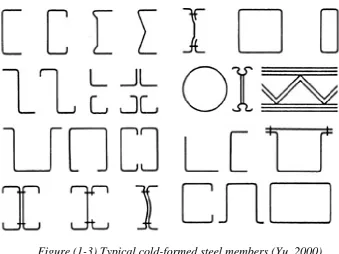
Figure (1-3) Typical cold-formed steel members (Yu, 2000) ... 3
Figure (1-4) Stress strain curve of cold-formed steel (Yu, 2000) ... 4
Figure (1-5) Failure of long columns due to instability, (Akin (2009)... 5
Figure (1-6) Linear (eigenvalue) buckling curve (Kurowski (2011) ... 7
Figure (1-7) Pin-ended column buckling modes, (Megson (2005) ... 8
Figure (2-1) Typical local buckling mode ... 14
Figure (2-2) Distortional buckling mode ... 15
Figure (2-3) Lateral distortional buckling mode ... 15
Figure (2-4) Lateral torsional buckling mode... 17
Figure (2-5) Lateral (global) buckling mode ... 17
Figure (2-6) Buckling load factor vs length for channel section, B Young and Rasmussen (1997) ... 18
Figure (2-7) (A) Test arrangement (B) specimen tested with pinned ends (torsionally restrained), (Casafont et al. ,2011) ... 22
Figure (2-8) Failure of pinned specimens: (A) 800 mm, (B) 1000 mm, (C) 1500 mm and (D) 1800 mm, (Casafont et al., 2011) ... 22
Figure (2-9) Schematic test set-up representation: test specimen, view of the column end support condition, (dos Santos et al. (2012) ... 23
Figure (2-10) 1) Finite element mode. 2) column sections (unit: mm), (Hansapinyo, 2015) .. 25
Figure (2-11) Concrete footing schematic view,( Craveiro et al. (2016) ... 26
Figure (2-12) Experimental test set-up built for buckling tests. ... 27
Figure (2-13) End-support devices. (a) general views of the end-support devices. (b) adjustable system adopted to fix each one of tested cross-sections. (c) pin-ended support. (d) fix-ended support, (Craveiro et al. (2016) ... 27
Figure (2-14) GBTUL program views, (Bebiano et al, 2008) ... 29
Figure (2-15) Von Mises stress (Ơmises, N/mm2) contours at equilibrium state: column sides under (a) compression and (b) tension, (Nuno Silvestre et al., 2012) ... 32
XI
(Pi and Trahair, 1995) ... 36
Figure (2-18) General comparison of test and FE models, C. Yu and Schafer (2006) ... 39
Figure (2-19) Torsional strengthened MW/HW upright section with channel stiffener and its boundary condition rack system, Thombare et al. (2016) ... 40
Figure (2-20) Eigen buckling analysis modes for frame MWB2-1.6 mm thickness, (Thombare et al. (2016) ... 41
Figure (2-21) Buckling modes vs member length ... 42
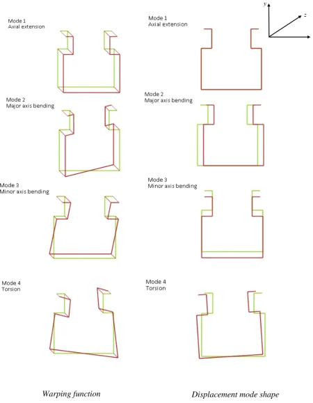
Figure (3-1) Warping function and displacement mode shape rigid body modes, (GBTUL).. 49
Figure (3-2) Warping function and displacement mode shape of higher order distortional and local modes, (GBTUL) ... 50
Figure (3-3), Global and local coordinations, Schardt (1966) ... 53
Figure (3-4) Displacement of node, Schardt (1966) ... 55
Figure. (3-5) Membrane strain , Schardt (1966) ... 67
Figure (3-6) Membrane shear deformation , Schardt (1966)... 73
Figure (4-7) Resolution of applied load parallel and normal to a section, Schardt (1966) ... 76
Figure (4-1) Pinned end ... 80
Figure (4-2) Fixed end ... 80
Figure (4-3) Equivalent axial loading ... 82
Figure (4-4) Top hat-section ... 83
Figure (4-5) GBTUL section properties, (Bebiano et al, 2008) ... 84
Figure (4-6) CUFSM section properties, (Schafer, 2006) ... 85
Figure (4-7) Rack column section ... 92
Figure (4-8) GBT & Euler buckling loads... 94
Figure (4-9) Buckling load vs length of column for each mode indi vidually for pinned-pinned ends conditions ... 95
Figure (4-10) Buckling load vs length of column for each mode individually for fixed-pinned ends conditions ... 95
Figure (4-11) Buckling load vs length of column for each mode individually for fixed-fixed ends conditions ... 95
Figure (4-12) Flow chart illustrates procedures to calculate critical buckling loads in both single and combined modes ... 97
XII
pinned-pinned boundary conditions, (Bebiano et al, 2008)... 98
Figure (4-15) Buckling load vs length of column with combined modes in CUFSM for pinned-pinned boundary conditions, (Schafer, 2006) ... 99
Figure (4-16) Buckling load vs length of column with combined modes for all programs for pinned-pinned boundary conditions ... 99
Figure (4-17) Buckling load vs length of column with combined modes in matlab program for pinned-fixed boundary conditions ... 100
Figure (4-18) Buckling load vs length of column with combined modes in GBTUL for pinned-fixed boundary conditions, (Bebiano et al, 2008) ... 100
Figure (4-19) Buckling load vs length of column with combined modes ... 101
Figure (4-20) Buckling load vs length of column with combined modes in all programs for pinned-fixed boundary conditions ... 101
Figure (4-21) Buckling load vs length of column with combined modes in matlab program for fixed-fixed boundary conditions ... 102
Figure (4-22) Buckling load vs length of column with combined modes in GBTUL for fixed-fixed boundary conditions, (Bebiano et al, 2008) ... 102
Figure (4-23) Buckling load vs length of column with combined modes in CUFSM for fixed-fixed boundary conditions ... 103
Figure (4-24) Buckling load vs length of column with combined modes in all programs for fixed-fixed boundary conditions ... 103
Figure (4-25) Flow chart of non-linear analysis of yielding load of column subjected to an axial load with initial imperfection ... 105
Figure (4-26) Non-linear load vs length of column with pinned-pinned boundary conditions ... 106
Figure (4-27) Non-linear load vs length of column with pinned-fixed ends boundary conditions ... 107
Figure (4-28) Non-linear load vs length of column with fixed-fixed ends boundary conditions ... 107
Figure (5-1) Element geometry (Ansys, 2007) ... 110
Figure (5-2)Stress-strian curve (Ansys, 2007) ... 111
Figure (5-3) Modelling with the direct generation method ... 113
Figure (5-4) Modelling with the solid modelling method ... 116
Figure (5-5) Meshing types ... 117
XIII
Figure (5-8) Pinned end support modelling ... 122
Figure (5-9) Fixed end support ... 123
Figure (5-10) Nonlinear stress-strain curves ANSYS modelling ... 127
Figure (5-11) Solution control ... 127
Figure (5-12) Solution control, nonlinear options ... 128
Figure (5-13) Cladding section ... 128
Figure (5-14) Pinned end support (ANSYS model) ... 129
Figure (5-15) Linear and non-linear buckling load versus column length for pinned end support ... 129
Figure (5-16) Linear and non-linear buckling mode shapes for pinned end conditions at a length of 1.0 metre ... 130
Figure (5-17) Linear and non-linear buckling mode shapes for pinned end condition for a length of 2.0 meters ... 130
Figure (5-18) Linear and non-linear buckling mode shapes for pinned end conditions for a length of 3.0 metres ... 131
Figure (5-19) Linear and non-linear buckling mode shapes for pinned end condition for a length of 4.0 metres ... 131
Figure (5-20) Non-linear buckling load versus displacements of max. displacement point for pinned end conditions for a length of 1.0 metre ... 132
Figure (5-21) Non-linear buckling load versus displacements of max. displacement point for pinned end conditions for a length of 2.0 metres ... 132
Figure (5-22) Non-linear buckling load versus displacements of max. displacement point for pinned end conditions for a length of 3.0 metres ... 133
Figure (5-23) Non-linear buckling load versus displacements of max. displacement point for pinned end conditions for a length of 4.0 metres ... 133
Figure (5-24) Penned end ANSYS modelling ... 134
Figure (5-25) Linear and non-linear buckling load versus column length for fixed end support ... 134
Figure (5-26) Linear and non-linear buckling mode shapes for fixed end conditions for a length of 1.0 metre ... 135
Figure (5-27) Linear and non-linear buckling mode shapes for fixed end condition for a length of 2.0 metres ... 135
XIV
length of 4.0 metres ... 136
Figure (5-30) Non-linear buckling load versus displacements of max. displacement point for fixed end conditions for a length of 1.0 metre ... 137
Figure (5-31) Non-linear buckling load versus displacements of max. displacement point for fixed end conditions for a length of 2.0 metres ... 137
Figure (5-32) Non-linear buckling load versus displacements of max. displacement point for fixed end conditions for a length of 3.0 metres ... 138
Figure (5-33) Non-linear buckling load versus displacements of max. displacement point for fixed end conditions for a length of 4.0 metres ... 138
Figure (6-1) Test sections ... 142
Figure (6-2) (GBTUL) eigen-buckling analysis ... 143
Figure (6-3) (GBTUL) eigen-buckling analysis ... 143
Figure (6-4) Micrometre screw gauge and Mikrotest ... 145
Figure (6-5) Overview of the test set-up ... 146
Figure (6-6) Test rig sections ... 146
Figure (6-7) Schematic of loading system ... 147
Figure (6-8) Loading system ... 148
Figure (6-11) Linear variable displacement transducer (LVDT) ... 150
Figure (6-12) Vertical displacement measuring system ... 151
Figure (6-13) Data logger measuring system ... 151
Figure (6-14) Related effect of vertical movement on horizontal movement ... 152
Figure (6-15) Horizontal displacement measuring system ... 153
Figure (6-16) Tilting device ... 154
Figure (6-17) Tensile test sheet specimens... 156
Figure (6-18) Preparing of tensile sheet specimens ... 157
Figure (6-19) Stress-strain relationship under uniaxial tensile loading, (Hakim et al., 2015) 158 Figure (6-20) The extensometer ... 160
Figure (6-21) Measuring of the tensile sheet coupon ... 162
Figure (6-22) the Tensile test ... 161
Figure (6-23) Comparative stress-strain relationships of section (Z-200-(64-54) -(18-15)-2.0) ... 162
Figure (6-24) Comparative stress-strain relationships of section (C-200-60-14-1.770) ... 163
Figure (6-25) Comparative stress-strain relationships of section (C-170-60-14-1.431) ... 163
XV
Figure (6-28) Universal hydraulic machine... 168
Figure (6-29) Concrete block fixed end support ... 169
Figure (6-30) Concrete block fixed end testing ... 170
Figure (6-31) Load- axial displacement relationship of specimens with fixed ends represented by concrete blocks ... 171
Figure (6-32) Welded fixed end testing ... 172
Figure (6-33) Welded fixed end testing ... 173
Figure (6-34) Load- axial displacement relationship of welded fixed end support... 174
Figure (6-35) Schematic of clamped fixed end condition ... 175
Figure (6-36) Clamped fixed end testing ... 175
Figure (6-37) Tension control bolts , (Casgrove, 2004) ... 176
Figure (6-38) Electric shear wrench ... 176
Figure (6-39) Clamped fixed end testing ... 177
Figure (6-40) Load- axial displacement relationship of clamped fixed end support... 178
Figure (6-41) Finite element mesh of (10 mm) square shape shell element with aspect ratio constant at 1:1 ... 179
Figure (6-42) Fixed end support and applied load modelling ... 180
Figure (6-43) Finite element failure mode shape ... 181
Figure (6-44) Nonlinear failure stress distribution ... 182
Figure (6-45) Buckling load-axial displacement relationship of nonlinear finite element analysis (ANSYS) ... 182
Figure (6-46) Modification of clamped end to work with lipped channel and zed-section ... 184
Figure (6-47) Two and three pins loading systems ... 185
Figure (6-48) Punching of section plate elements ... 186
Figure (7-1) Cross-section gbt nodes... 187
Figure (7-3) GBT Z-section buckling modes, (Bebiano et al, 2008), 25th, November 2016 189 Figure (7-4) Buckling load versus length of the C-section of each single mode with pinned end conditions ... 191
Figure (7-5) buckling load versus length of the C-section of each single mode with fixed end conditions ... 191
Figure (7-6) buckling load versus length of the Z-section of each single mode with pinned end conditions ... 192
XVI
XVII
XVIII
XIX
XX
XXI
XXII
XXIII
XXIV
I would like to thank the following people and organisations for supporting me in numerous ways throughout my PhD. First and foremost, I am indebted to my supervisor
Dr.
Lawrence Weekes
for his continuous support and guidance throughout the PhD process. Lawrence, I am so lucky to have you as my supervisor and I would have never completed my PhD without your knowledge, advice and most importantly your encouragement! I would also like to extend my gratitude to my co-supervisorDr. Philip Leech
for his guidance during the PhD. Philip, I am really appreciated your help and support throughout all the difficult times that I faced before finishing my PhD. Deep thanks from my heart.I would like to take this opportunity to thank the
Iraqi ministry of higher education
and scientific research,
their representativeIraqi cultural attaché
and theUniversity
of Basra/ Collage of engineering
for offer me this opportunity to finish my PhD here in the UK. Also, I would like to thank theSchool of Computing, Science and
Engineering
for their help and support during my PhD journey. I am grateful to the academic and support staff from theSchool of Computing, Science and Engineering
for their efficient service and support.Special thanks to the civil engineering laboratory staff,
Philip Letham, Antony
Burrage & Mark Avis
. Without their support, I would not have completed the PhD as expected. I would also like to thank all my friends especiallyAmmar Dakhil & Osamah
Salim
for their help and support.XXV
Dedication
XXVI
This thesis is submitted to the University of Salford rules and regulations for the award of a PhD degree by research. While the research was in progress, some research findings were published in refereed journals and conference papers prior to this submission (refer to Appendix G).
The researcher declares that no portion of the work referred to in this thesis has been submitted in support of an application for another degree of qualification of this, or any other university or institution of learning.
1
CHAPTER ONE
INTRODUCTION
1.1 General
There are two types of steel members in production, namely hot rolled steel members that are rolled in specialised factories with high temperatures and cold formed steel members that are formed at normal atmospheric temperatures. Hot rolled sections are thicker gauge, provide increased strength and stiffness over cold rolled steel, and are used in general domestic and commercial building construction. Light gauge steel tends to be used for building projects that require less weight to be supported i.e. small portal frames and storage racking. The use of light gauge cold formed steel is increasing rapidly due to its structural characteristics and economy. This type of steel has been used widely in residential, industrial and commercial buildings, bridges, storage racks, grain bins, car bodies, railway coaches, highway products, transmission towers, transmission poles and drainage facilities.
1.2 Manufacturing methods of cold-formed steel
There are two methods used in the manufacture of cold formed steel sections:
1.2.1 Cold roll forming machines
2
1.2.2 Press braking
The equipment used in press breaking operations essentially consists of a moving top beam (punch) and a stationary bottom bed (die) that produce one complete fold at a time along the full length of the beam, figure (1-2).
The press-braking operation is normally used to produce small quantities of various shaped sections. The initial cost of cold roll forming is higher than the press-breaking method;
Figure (1-1) Cold-formed C-section sequences (www.custompartnet.com 27th, March 2014)
[image:30.595.90.532.407.653.2]3
range of typical sections which are commonly used for light gauge steel members.
Most of the recent research demonstrates that cold formed steel sections are more economical than hot-rolled steel sections; light gauge cold-formed steel sections have the following advantages:
- Ease of manufacturing and mass production. - Uniformity and high quality control.
- Low self-weight.
- Ease and economy of transportation and handling. - Fast and simple erection or installation.
- Improved technology of manufacture and corrosion protection. - Non-shrinking and non-creeping at ambient temperature.
- Improved production of complex shapes (since modern rolling lines are computer controlled, highly complex sections can be produced).
The issues with cold-formed members are that the stiffness tends to be less when compared to hot rolled members, so there may be more displacement in the member and also at the connections. Increased displacements tend to mean that elastic instability is more of an issue with cold-formed members. Light gauge cold-formed steel sheets have thicknesses ranging from 0.4 to 6.4 mm, Yu (2000). Referring to figure (1-4), the nominal yield strength of available cold-formed steel ranges from 250 to 550 N/mm2, Yu (2000). The yield strength of
[image:31.595.124.464.113.367.2]4
Figure (1-4) Stress strain curve of cold-formed steel (Yu, 2000)
determined from the slope of the graph (approximately 200,000 N/mm2), Yu (2000).
1.3 Buckling terminology
To address the buckling phenomena in light gauge cold formed steel sections the following terms require clarification.
The radius of gyration, r, is the units of length that describes the way in which the area of a cross section is distributed around its centroidal axis.
𝑟𝑟 = �𝐼𝐼
𝐴𝐴 (1 − 1)
Where I and A are the area moment of inertia, and area of the cross section respectively.
Slenderness is a geometric concept of a two-dimensional area that is quantified by the length of a particular member divided by its ratio of the radius of gyration,
𝜆𝜆 =
𝐿𝐿𝐸𝐸𝑟𝑟.
Stiffness is a structural property, which is proportional to the elastic modulus E (Young’s modulus) and the section geometry in the equation:
𝐴𝐴𝐴𝐴𝐴𝐴𝐴𝐴𝐴𝐴 𝑆𝑆𝑆𝑆𝐴𝐴𝑆𝑆𝑆𝑆𝑆𝑆𝑆𝑆𝑆𝑆𝑆𝑆 =𝐸𝐸𝐴𝐴𝐿𝐿 (1 − 2)
5
Slender or thin walled components under compressive stress are susceptible to buckling. Most people have observed what is called Euler buckling where a long slender member subject to a compressive force moves laterally to the direction of that force, as illustrated in Figure (1-5). Euler buckling is a purely theoretical instability problem and tends to provide an upper bound to real physical buckling which accounts for plasticity/nonlinearity in the material. The force, F, necessary to cause such a buckling motion will vary by a factor depending only on how the two ends are restrained. (i.e. for a pin ended member), as summarised in Megson (2005).
1.3.2 Buckling load factor
The buckling load factor (BLF) is an indicator of the factor of safety against theoretical buckling or the ratio of the buckling loads to the currently applied loads.
Table (1-1) ‘Interpretation of the Buckling Load Factor (BLF)’ illustrates the interpretation of possible BLF values.
[image:33.595.93.541.402.623.2]6
BLF Value Buckling Status Remarks
>1 Buckling not predicted
The applied loads are less than the estimated critical loads.
= 1 Buckling predicted
The applied loads are exactly equal to the critical loads.
Buckling is expected.
< 1 Buckling predicted
The applied loads exceed the estimated critical loads. Buckling will occur.
‐1 < BLF < 0 Buckling possible
Buckling is predicted if you reverse the load directions.
‐1 Buckling possible
Buckling is expected if you reverse the load directions.
< ‐1 Buckling not predicted
The applied loads are less than the estimated critical loads, even if you reverse their directions.
1.4 Buckling analysis
Buckling analysis is a technique used to determine theoretical buckling loads (critical loads) at which a structure becomes unstable and buckled mode shapes, i.e. the characteristic shapes associated with a structure's buckled response.
1.4.1 Linear buckling analysis (eigenvalue problem)
The solution of second order differential buckling equations leads to a series of eigenvalues which represent critical loads, and eigenvectors which represent the associated buckled mode shape. Referring to figure (1-6) for instance, an eigenvalue buckling analysis of a pin ended column will match the classical Euler solution (eq. (1-3). However, imperfections and nonlinearities in both material and section geometry prevent most real-world structures
Table (1-1) Interpretation of the buckling load factor (BLF) (Akin (2009)
7
analysis tends to envelope the failure load, and is usually modified accounting for nonlinearities to provide design load capacities.
Linear eigen-buckling analyses provide theoretical buckling load magnitudes and associated buckling modes. FEA programs provide calculations of a large number of buckling modes and the associated buckling load factors (BLF) through eigenvalue calculations, Kurowski (2011).
The BLF is expressed as a number by which the applied load must be multiplied (or divided depending on the particular FEA package) to obtain the buckling load magnitude.
The buckling mode illustrates the shape the structure assumes when it buckles in a particular mode, but does not represent numerical values of the displacements or stresses mainly because the analysis is not one which is loaded. The numerical values can be displayed, but are merely relative. Also in the linear (Eigenvalue) buckling, the member may be shown to have buckled in the opposite direction to that predicted. This is not an error; merely the linear buckling analysis only predicts the buckled shape (mode) and not the direction of buckling.
Linear buckling critical load analysis overestimates the real buckling load and provides non-conservative results when compared to actual physical critical loads due to the effects of
Figure (1-6) Linear (eigenvalue) buckling curve (Kurowski, 2011) Bifurcating point
Limit load (from nonlinear buckling)
8 should represent the actual geometry of the beam.
The well-known buckling load for a pin-ended column is:
𝑃𝑃𝐸𝐸 = 𝑆𝑆
2𝜋𝜋2𝐸𝐸𝐼𝐼
𝐿𝐿2 (1 − 3)
Where n = 1, 2, 3, …..
Figure (1-7) shows the higher values of buckling load correspond to more complex buckling mode shapes which can be formed by introducing intermediate restraints along the member length (at the points of contraflexure).
For use in design the Perry-Robertson formula is used which accounts for material nonlinearity and geometric tolerances. This provides design values of axial failure load which account for buckling in long slender beams and is the basis for the design adopted in, Code (2007). The formula in question can be expressed in the following form:
𝜎𝜎𝑚𝑚 =12 (𝑆𝑆𝑦𝑦+ 𝜎𝜎𝑒𝑒(1 + 𝜃𝜃) − ��𝑆𝑆𝑦𝑦+ 𝜎𝜎𝑒𝑒(1 + 𝜃𝜃)�
2
− 4𝑆𝑆𝑦𝑦𝜎𝜎𝑒𝑒 (1 − 4)
with
[image:36.595.88.526.289.522.2]9
𝜃𝜃 = 𝐴𝐴2
Where:
• is the average longitudinal stress in the beam's cross-section.
• is the material's elastic limit.
• is the average tension measured in the cross section which corresponds to the beam's Euler load.
• the amplitude of the initial geometrical imperfection.
• is the distance from the cross section's centroid to the section's most stressed fibre.
• the section's radius of gyration.
1.4.2 Nonlinear analysis
Nonlinear analysis incorporating both material and geometric nonlinearity provides more realistic behaviour and is therefore recommended for design or evaluation of actual structures. This technique employs a nonlinear static analysis with gradually increasing loads to seek the load level at which the structure becomes unstable.
Using the nonlinear approach, the model can include features such as initial imperfections, plastic behaviour, gaps, and large deflection response. In addition, using deflection-controlled loading, it can track the post-buckled performance of the structure (which can be useful in cases where the structure continues to carry load past the theoretical critical load i.e. local and distortional buckling modes).
1.5 Buckling analysis methods
A number of researchers have conducted both numerical and experimental analyses, and have recommended analysis methods for light gauge steel members to predict the buckling loads, modes, and to predict how these structures will perform when subject to axial or flexural loads. Consequently, various alternative methods of analysis have been introduced and here are some of them.
10
1.6 Aims and objectives
The above methods (which will be described in detail in the following chapters) have already been written into computer codes to predict the theoretical buckling modes and capacities of various light gauge steel open sections.
So far GBT has been implemented using the finite difference solution technique P Leach and Davies (1996), and the finite element method (Bebiano et al. (2008)). The aim will be to extend the GBT method (currently only employed for providing linear buckling loading and modes solved using FD methods) to incorporate nonlinear geometry effects and provide a prediction of real behaviour up to the onset of material yield.
This will be achieved by reproducing the GBT code in MATLAB, firstly verified against the other available codes, then extending this to nonlinear finite element analyses. The results will be supported by findings from experimental axial tests on a number of light gauge steel sections
In addition, this will also inform the efficiency and suitability of sections, including boundary conditions for various structural usage.
In order to reach these goals, the research will be divided into four steps, namely a literature study, modelling, applications and verification.
Firstly, a literature review will be performed regarding the concept of modelling cold formed steel sections in order to collect important information as well as documenting the development of modelling methods from their beginnings until the present date.
Later, conduct comparative studies of the buckling behaviour of light gauge cold-formed steel compression members with respect to pin-ended and fixed-ended conditions, using the finite strip method (CUFSM) software and generalized beam theory (GBTUL) software.
To develop finite element models capable of simulating the elastic buckling and nonlinear ultimate strength behaviour of light gauge cold-formed steel compression members using the finite element program (ANSYS) and validate them using experimental results.
11
imperfection-actual buckling load relation) with different boundary conditions.
Finally, develop suitable experimental tests including evaluation of material properties, test sections, end support conditions, and loading rig set-up. The buckling tests for light gauge cold-formed steel compression members will validate the results of the numerical models including buckling behaviour and capacities for global, local and distortional buckling modes.
1.7 Contents of the thesis
The prediction of actual buckling loads and its mode shapes of cold-formed steel beams was investigated based on generalized beam theory, experimental tests and extensive finite element analyses have been developed in this thesis. This thesis contains eight chapters and the contents of each chapter (except this one) are briefly described as follows:
- Chapter Two, literature review, provides the background concerning research on column buckling behaviour as applied to light gauge steel sections and some of the analysis methods employed to understand it.
- Chapter Three, formulation of the generalized beam theory, describes the behaviour of an open section beam under applied load with several corresponding modes of behaviour according to specific warping displacement functions.
- Chapter Four, applications of the generalized beam theory, presents the applications of the first and second order generalized beam theory using the Matlab
code in both linear and non-linear analysis to find the theoretical buckling and failure loads of open-section cold-form steel sections.
- Chapter Five, the finite element analysis, presents the linear eigenbuckling and non-linear material and geometric analyses
- Chapter Six, the experimental investigations of cold-formed steel members subjected to axial loads, presents the experimental testing of 36 cold‐formed steel (lipped C‐section and Zed-section) columns with different boundary conditions. The tests comprised lipped channel & Zed sections full-scale cold-formed steel columns of nine different lengths (two specimens for each length) subjected to axial loading for both pinned and fixed end conditions.
12
and the Generalized Beam Theory (GBT) using nonlinear analysis with the effects of initial imperfections and post-buckling effects to verify the best numerical analysis method, and also to discuss the features of each analysis method.
CHAPTER TWO
13
CHAPTER TWO
LITERATURE REVIEW
Many researchers have studied the buckling behaviour of cold-form steel sections and most of them have examined channel and Zed cross sections, but there appears to be a lack of research, carried out regarding the actual behaviour of these sections under axial and/or flexural loading. This literature review provides the background concerning research on column buckling behaviour as applied to light gauge steel sections and some of the analysis methods employed to understand it.
2.1 Buckling modes
Unfortunately, the behaviour of light gauge cold-form steel sections subjected to axial compression loading is still not fully understood. The behaviour of these sections exhibits different types of buckling, i.e. local buckling, distortional bucking and global buckling; for example, most lipped C-section short columns subjected to concentric compression loads fail because of a combination of local buckling of thin plate elements and distortional buckling of the edge stiffeners. However, there is a lack of research, which addresses how and where these modes happen and the interaction between them.
2.1.1 Local buckling
Local buckling is the buckling of individual plate elements which are under compression without changing the fold lines of the cross-section as shown in Figure (2-1). In the case of beams, local buckling may occur in the compression flange or part of the web which is under compression. Local buckling is characterised by short half wavelengths compared to the other buckling modes. Further, the half-wave length of local buckling is in the order of the width of the individual plate elements.
14
𝑆𝑆𝑐𝑐𝑟𝑟 = 𝑘𝑘𝜋𝜋
2𝐸𝐸
12(1 − 𝑣𝑣2) �
𝑆𝑆 𝑏𝑏�
2
(2 − 1)
Where k is called the plate local buckling coefficient which depends on the support conditions, and (b/t) is the plate aspect ratio in which b is the plate width and t is the plate thickness.
A plate element is said to be slender if the elastic critical local buckling stress (fcr)
calculated using the above equation is less than the material yield strength. Therefore, if a particular section is slender, local buckling takes place prior to the stresses reaching the yield strength. This leads to a large reduction of section moment capacity of beams because local buckling and the material yielding are the two failure criteria that govern the section moment capacity. If the elastic critical buckling stress (fcr) exceeds the yield stress, the plate element
under compression buckles in the inelastic range (Yu, 2000).
If the beam carries increasing load after the local buckling failure, the beam is said to have post-local buckling capacity. Therefore, even if the local buckling occurs in a plate element prior to yielding it does not necessarily mean that the failure of the section has occurred. Normally the post-buckling reserve is allowed for in the design to achieve an economic solution (Hancock and Rogers 1998).
2.1.2 Distortional buckling
Distortional buckling is the phrase used to describe the state when a flange rotates at the intersection point of flange and web in members provided with edge stiffeners, and for members which are intermediately stiffened. It occurs when the intermediate stiffener has a displacement normal to the plane of the member, as shown in Figure (2-2).
This type of buckling may occur in thin sections in compression or bending at stresses significantly below the yield stress, especially for high strength steels (Hancock and Rogers 1998). The half wavelength of distortional buckling is generally in between that of local buckling and lateral torsional buckling and typically several times larger than the largest characteristic dimension of the section.
15
If the sections are composed of high-strength steel, then there may be a significant post-buckling reserve of strength beyond the elastic distortional post-buckling stress in a similar manner to that which normally occurs for local buckling (Kwon and Hancock, 1992). Distortional buckling has less post-buckling capacity than local buckling modes, according to Schafer and Peköz (1999). This is also observed experimentally by Hancock et al. (1994). Distortional buckling failures occur even when local buckling occurs at a lower critical elastic moment than distortional buckling because of reduced post-buckling strength in the distortional failure mode (Schafer and Peköz, 1999).
2.1.3 Lateral distortional buckling
Lateral distortional buckling involves transverse bending of the vertical web and is most likely to occur if the tension flange is restrained, figure (2-3). This type of buckling often occurs in hollow flange beams because the tubular flanges of hollow flange beams are very stiff torsional while their webs are comparatively slender and easily undergo web distortion. Even though, when the tension flange is not restrained laterally and flanges are not torsional stiff, cold-formed C-section beams may still fail by lateral distortional buckling if the web is particularly slender ( Pi et al. 1998).
Figure (2-2) Distortional buckling mode.
[image:44.595.270.331.237.368.2]16
2.1.4 Lateral torsional buckling
Lateral torsional buckling failure is the most complex failure criterion of steel beams. This type of failure is identified by the simultaneous bending and twisting of the entire cross-section without cross-cross-sectional deformation, figure (2-4). If a beam is not restrained laterally, it tends to fail by lateral torsional buckling in cases where lateral stiffness and torsional stiffness are low. It occurs generally if the beam has a higher bending stiffness in the vertical plane compared to the horizontal plane. Because of the geometry of the open cross-section, which gives great flexural rigidity about one axis at the expense of low torsional rigidity and low flexural rigidity about a perpendicular axis, cold-formed steel members are particularly susceptible to lateral-torsional buckling according to Chu et al. (2004). The parameters affecting lateral torsional buckling resistance are the length between lateral restraints, the type and the positions of load, the geometry of cross-sections, the type of end supports, the presence or absence of stiffening devices that restrain warping at critical locations, the material properties, the magnitude and distribution of residual stresses, initial imperfections of geometry and loading, and cross-sectional distortion (Galambos, 1998).
Lateral torsional buckling behaviour is related to buckling resistance and slenderness. There are three different ranges of behaviour namely, elastic buckling, inelastic buckling and plastic behaviour. Elastic lateral torsional buckling occurs in slender beams with low resistance to lateral bending and twisting. As the slenderness decreases, the resistance of a beam to elastic buckling increases and the beam may yield before its elastic buckling moment is reached. Yielding reduces the effective out-of-plane rigidities, and hence, lateral torsional buckling occurs before reaching the elastic buckling moment. This type of buckling of beams having intermediate slenderness is called ‘inelastic lateral torsional buckling’. If the beam is fully or adequately restrained laterally so that the slenderness is low, it achieves the full plastic moment capacity.
The elastic critical buckling moment for lateral torsional buckling of an I-beam subjected to pure bending is given in equation (2-2), (Hill, 1954).
𝑀𝑀𝑐𝑐𝑟𝑟 = ��𝜋𝜋2𝐿𝐿𝐸𝐸𝐼𝐼𝑦𝑦2 � �𝐺𝐺𝐺𝐺 +𝜋𝜋2𝐿𝐿𝐸𝐸𝐼𝐼2 𝑤𝑤� (2 − 2 )
In Equation 2.2, EIy, GJ and EIw are the minor axis flexural rigidity, torsional rigidity and
17
2.1.5 Lateral (global) buckling
Global buckling describes the state when the cross section of a column remains unchanged while the column itself has either lateral or lateral torsional displacement, figure (2-5) BSI (2014).
2.2 Experimental investigations
Celebi et al. (1972) conducted tests on two unlipped cold-formed C-section beams loaded eccentrically through the web. Put et al. (1999) conducted approximately 160 tests on lipped and unlipped simply supported cold-formed steel beams loaded above the top flange, either through the web or centroid at the mid-span. The test results showed that the strengths of the beams loaded through the centroid were significantly lower than those loaded through the web. Kavanagh and Ellifritt (1994) reported ten tests of discretely braced cold-formed steel C-section beams loaded at the web centerline and these tests indicated that the strengths generally increased as the amount of bracing increased. Ellifrit et al. (1991) and Winter et al. (1949) have observed the same in their tests conducted on C-section beams.
18
Young and Rasmussen (1997) conducted an experimental investigation into the behaviour of cold-formed plain and lipped channel columns axially loaded with different boundary conditions such as fixed and pinned ends. It was shown experimentally that local buckling does not occur as a result of overall bending in the case of fixed-ended singly symmetric columns, as it does for pin-ended singly symmetric columns. They found that local buckling has a fundamentally different effect on the behaviour of pin-ended and fixed-ended singly symmetric columns, so a series of tests was performed on plain and lipped channels, brake-pressed from high strength structural steel sheets to examine this fundamentally different effect caused by local buckling, as shown in figure (2-6). Four different cross-section geometries were tested over a range of lengths which involved pure local buckling, distortional buckling as well as overall flexural buckling and flexural-torsional buckling. They also discovered that local buckling influenced the strength of short and intermediate plain channel columns, while for short and intermediate lipped channel columns with fixed-ends distortional buckling was more likely to influence their capacity. Although the local buckling mode does not affect long lengths or some intermediate column lengths significantly, its effects appear to be clearly obvious in short length columns during ultimate loading.
Put et al. (1999) performed bending and torsion tests on unbraced simply supported cold-formed steel channel beams loaded eccentrically at the mid-span. The test results showed that the beam strengths decrease as the load eccentricity increases and that the strength is higher when the load acts on the centroid side of the shear centre than when it acts on the side away from the shear centre. They developed simple interaction equations that can be used in the design of eccentrically loaded cold-formed channel beams.
19
Kesti and Davies (1999) stated that the distortional mode is a critical buckling mode for columns made from cold-formed steel, which depends on the end boundary conditions and the length of the column as well as the effective area of the cross section.
Gotluru et al. (2000) investigated the behaviour of cold-formed steel beams subjected to torsion and bending because the transverse load was not applied at the shear centre. They performed simple geometric nonlinear analyses, finite element analyses and finite strip analyses and compared their results with experimental results. The influence of typical support conditions was studied and they were found to produce partial warping restraints at the ends. Yu (2000) provides numerical methods for calculating torsional properties of thin-walled sections.
Rondal (2000) stated that the distortional buckling mode is a relatively new mode to be considered, also there is a lack of research which compares local and global buckling. However, due to the continual evolution of steels with higher strength formed in thinner sections, distortional buckling could sometimes be considered as a more critical factor than other modes of buckling in more modern structures.
Schafer (2002) found that the distortional buckling stresses in lipped sections are higher than other sections, especially in sections that have lips which are nearly equal in length to the flange width, so these types of sections are better at resisting distortional buckling.
Yu (2000) stated that torsional buckling did not occur in closed sections because of their large torsional rigidity, whereas for open thin-walled sections, flexural buckling and flexural-torsional buckling are both possible. The doubly symmetric sections may fail by pure bending (flexural buckling) and the single symmetric sections may fail either by bending about the weak axis (flexural buckling) or by bending about one axis and twisting about the shear centre (flexural-torsional buckling) depending on factors related to the cross-section properties and the effective length of the column.
20
Hancock (2003) examined the behaviour of members undergoing distortional buckling and the interaction of this mode with other buckling modes. Most of his research looked at simple lipped channel sections.
Narayanan and Mahendran (2003), described the distortional buckling behaviour of a series of innovative cold-formed steel columns. More than 15 laboratory experiments were undertaken on these innovative steel columns of an intermediate length under axial compression. All of these columns failed by distortional buckling with very little post-buckling strength. The section and buckling properties of the columns were determined using the finite strip analysis. The distortional buckling and nonlinear ultimate strength behaviour of the columns was investigated in detail using finite element analyses (ABAQUS). The finite element analyses included relevant geometric imperfections and residual stresses. The deflection and strain results from the experiments compared well with those from the analyses. The ultimate design load capacities were evaluated using the provisions of Australian Cold-formed Steel Structures Standard AS/NZS 4600-1996 and were compared with those from experiments and finite element analyses. A series of parametric studies was also carried out by varying the yield strength, thickness and column length.
de Barros Chodraui et al. (2006) were of the same opinion with the later conclusions of Schafer (2002) about wide flanges. He also studied the behaviour of wide flanges provided with edge stiffeners in cold forms steel sections such as rack, top hat Z, and lipped channels where there are usually wide flanges and lips at the edges. He concluded that these sections are most sensitive to distortional buckling modes rather than others.
21
displacements due to lateral-torsional buckling in the direction of the open part of the section led to a ductile failure with no abrupt decline of the load carried. Higher failure moments were observed if the beams failed in the positive direction as compared to those beams with negative imperfections.
Brune and Ungermann (2008) carried out numerical investigations of channel beams subject to coupled instabilities. Numerical models were validated using the test results of Ungermann and Dortmund (2006). They found out that the DSM and EC 3 Part 1.3 overestimate the ultimate loads for thin-walled slender channels in bending.
Kwon et al. (2009) tested a series of cold-formed lipped channels in compression both with and without intermediate stiffeners with fixed ends. The channels were fabricated from 0.6 and 0.8 mm thicknesses of high strength steel plate where the nominal yield stress was 560 N/mm2. The aim of their research was to study the ultimate strength of columns with intermediate lengths. They discovered that for sections with local buckling as the critical buckling mode, the interaction between the local and distortional buckling modes was observed only in stub columns and an interaction between the local and global buckling modes was the final failure mode in the intermediate and long length columns. However, for sections with distortional buckling as the critical buckling mode, stub and intermediate length columns experienced critical failure mode induced from the interaction between local and distortional buckling modes, and the interaction of local, distortional and global buckling modes occurred in some of the columns’ lengths. Finally, it can be said that the existence of the buckling mode interaction within column behaviour in compression depends highly on the cross-section properties and the boundary conditions of the column.
22
dos Santos et al. (2012), Silvestre et al. (2012) and Dinis et al. (2007) stated that most open cross section members formed from cold-formed steel have high local and global slenderness, and this makes them oversensitive to geometrical instability phenomena such as local, distortional and global (flexural or flexural-torsional) buckling. Many factors affect the failure mode such as the length, shape and dimensions of cross section and the end support conditions of the member.
Figure (2-7) (A) Test arrangement (B) specimen tested with pinned ends (torsionally restrained) (Casafont et al., 2011).
Figure (2-8) Failure of pinned specimens: (A) 800 mm, (B) 1000 mm, (C) 1500 mm and (D) 1800 mm (Casafont et al., 2011).
A B
23
dos Santos et al. (2012) proved that there is a triple interaction between local, distortional and global buckling in lipped channel column sections. They also identified its influence on their 12 lipped channel test samples, and concluded that the failure mode of the columns was a combination of symmetric distortional and flexural-torsional buckling modes, figure (2-9).
Godat et al. (2012) investigated in their research the behaviour of the local buckling of tubular polygon columns formed from thin-walled steel, they tested three different cross sections, hexagonal (sixteen-sided), dodecagonal (twelve sided) and octagonal (eight-sided). They concluded that for various thin-walled tubular polygon columns with equal cross section area, it might become advantageous to minimise the plate slenderness ratio (plate width to thickness) due to the increase in local buckling capacity.
24
Ananthi et al. (2015), presented both the analytical and theoretical investigations on ultimate load carrying capacity and behaviour of CFS unlipped channels with their ends fixed and subjected to axial compression. The numerical studies were carried out in the elastic as well as in the plastic ranges of loading. The slenderness ratio of the channels chosen was 40, 80,100 and 120. Three different web depths (shallow, medium and deep) with five thicknesses were also chosen. In addition to the numerical studies, the comparison was made with the design strengths predicted by using North American Standards for CFS structures. It was observed that the design strength predicted by the specifications were conservative for axially loaded columns. In the present investigation, an attempt is made to study the ultimate load carrying capacity and the mode of failure. Load versus axial shortening behaviour has been studied for various slenderness ratios for a few specimens.
25
McCann et al. (2016) addressed the Numerical analysis of the local buckling behaviour and ultimate cross-sectional strength of tubular elliptical profiles in compression. After validating the model against previous experimental results, a parametric study comprising a total of 270 elliptical sections was conducted in order to examine the influence of cross-section aspect ratio, geometric imperfections and local slenderness. The obtained ultimate capacities, load–deformation responses and failure modes are discussed in the paper. It was found that for lower cross-section aspect ratios the behaviour of the elliptical hollow sections (EHS) was similar to that of cylindrical shells across a number of metrics; as the aspect ratio increased, more plate-like stable post-buckling behaviour was observed. A design method was proposed for Class 4 EHS members that reflect the reduction in capacity due to local buckling with increasing slenderness, but also recognises the improved post-buckling stability with increasing aspect ratio.
26
Valarinho et al. (2016), presented results of analytical, experimental and numerical studies on the lateral-torsional buckling (LTB) behaviour of long-span laminated glass beams. The analytical study was mainly focused (1) on the assessment of existing expressions for the determination of the effective flexural and torsional stiffness of 3-layer laminated glass beams and (2) on the determination of the buckling resistance and post-buckling behaviour of long-span laminated glass beams taking into account the influence of changes in the thickness of the glass panes and of the viscoelastic properties of the interlayers. The experimental study comprised a flexural test of a simply supported and unbraced 8.20 m long PVB 3-layer laminated glass fin. Finally, three-dimensional numerical models were also developed in order to simulate the experiments and validate the analytical results. The results obtained showed that the analytical formulae and the numerical tools available are able to accurately predict the LTB behaviour of long-span 3-layer laminated beams. The results also draw attention to the importance of adequately considering the influence of possible thickness reductions on the glass panes and of temperature and loading time effects on the shear behaviour of PVB interlayers.
Craveiro et al. (2016), presented an experimental investigation of the buckling behaviour of compressed single and built-up cold-formed steel columns. Four types of cross-sections were tested, namely, one single, one open built-up and two closed built-up, considering two end support conditions, i.e. pin-ended and fix-ended. The obtained results were compared with the design predictions of EN1993-1-3:2004 and AISI S100-07. For pin-ended lipped channel columns the design predictions were in good agreement with the experimental results, however, for the fixed ended columns, the predictions appeared to be conservative. For built-up columns, it was found that increasing number of different sections may lead to unsafe design predictions, figures (2-11), (2-12) & (2-13).
27
2.3 Theoretical investigations
A number of researchers have conducted both numerical and theoretical analyses, and have recommended analysis methods for light gauge steel members to predict the buckling loads, modes, and to predict how these structures will behave when subject to axial or flexural
Figure (2-13) End-support devices. (a) general views of the end-support devices. (b) adjustable system adopted to fix each one of tested cross-sections. (c) pin-ended support. (d) fix-ended
support (Craveiro et al. 2016).
28
loads. Consequently, various alternative methods of analysis have been introduced and the following section presents these.
2.3.1 Generalized beam theory (
GBT
)
GBT was first presented in the 1960’s by a German professor named Richard Schardt. The theory could be interpreted as a combination of the folded plate theory and the Vlasov’s theory for thin-walled beams (Simão, 2007).
29
compression members and, in particular, web-perforated sections. Finally, a recent article of (Davies, 2000) is concerned the analysis of thin-walled members with stiffened compression flanges.
2.3.1.1 GBTUL program
Bebiano (2008) GBTUL (an acronym for ‘GBT at the University of Lisbon’) is a freeware program that performs elastic buckling (bifurcation) and vibration analyses of prismatic thin-walled members. It implements the latest formulations of GBT that (i) accounts for local deformation and (ii) provides an advantageous representation of the deformation field, as a combination of structurally meaningful cross-section deformation modes.
Taking advantage of the GBT model features, the program provides information and visualisation of the member deformation modes. Moreover, it contains tools that make it possible to select the deformation modes to include in the analysis, thus allowing for an in-depth insight into the mechanics of the problem being solved. It is possible to analyse members (i) made of one or several isotropic or orthotropic materials, and (ii) exhibiting various common support conditions (e.g., simple supports, fixed supports or free ends). In the buckling analyses, the user is able to specify any combination of arbitrary axial force, bending moment and bi-moment (longitudinal) diagrams, see Figure (2-14).
Davies and Jiang (1996a), introduced the basic principles of GBT and showed how this theory may be used to analyse cold-form sections in which distortion of the cross-section is significant. The calculation is illustrated by detailed numerical examples.
30
Davies and Jiang (1996b) introduced the second order terms associated with geometric non-linearity into the basic equations for the load to cause buckling in individual modes under either axial load or uniform bending moment. Then they showed how the explicit procedure can be extended to consider the interaction between local, distortional and global buckling
modes.
The generalized beam theory is applicable to prismatic structural members to take into account the in-plane flexural and distortional cross section deformations and can be used to examine the three generic buckling modes and their interaction (Silvestre, 2007). The second order GBT was developed and introduced as an appropriate method for coupled stability problems by Schardt (1994), and then the GBT method was extensively used for investigating the elastic behaviour for open cross sections fabricated from cold-formed steel (Tomà and Wittemann, 1994). The early formulations of this theory were limited to isotropic thin-walled members to analyse the elastic buckling of unbranched open cross sections. New formulations of GBT were developed by Silvestre and Camotim (2003) to make the theory applicable to open branched and closed cross sections. This was followed by another formulation of the GBT developed by Gonçalves et al. (2009) and this new formulation was more general and capable of dealing with closed and open branched sections, with the applications’ domain of the GBT being extended to deal with the curved-wall members by Silvestre (2007).
Silvestre and Camotim (2006) presented GBT formulation for analysing the vibrational behaviour of loaded composite thin-walled members, which accounts for the effects of (i) cross-section in-plane deformation, (ii) shear deformation, (iii) geometric and material coupling, (iv) primary, secondary and non-linear warping, and (v) rotary inertia. Then they used the results to investigate the local and global vibration behaviour of lipped channel columns and beams displaying cross-ply orthotropic. They focused on issues dealing with the variation of the fundamental frequency and the vibration mode in relation to the member length and applied stress level. For validation purposes, they used some GBT-based results to compare with values obtained by means of 4-node shell model constructed using finite element analyses (ABAQUS).
31
the web crippling). In order to achieve this goal, the GBT formulation traditionally employed in buckling analyses was enhanced by including specifically: (i) non-linear terms and (ii) transverse extension modes. They stated that the GBT formulation/implementation is a very advantageous alternative to shell finite element analyses, the only available method to capture the localised effects rigorously. They presented and discussed numerical results concerning the buckling behaviour of (i) hat and I-section cantilevers acted upon by transverse tip point loads applied at various cross-section points, and (ii) I-section simply supported beams under top-flange distributed and point loads. One also assesses how end support transverse web stiffeners improve the beam buckling behaviour to illustrate the application and capabilities of the proposed GBT formulation-implementation. For validation, the GBT results were compared with previous values reported by ABAQUS shell finite element analyses.
32
Abambres et al. (2014), presented a formulation of GBT intended to perform first-order elastic–plastic analyses of thin-walled members experiencing arbitrary deformations and made of non-linear materials exhibiting isotropic hardening. After presenting the GBT fundamental assumptions and kinematic relationships, the member nonlinear equilibrium equations are derived and a non-linear one-dimensional (beam) finite element is formulated. The arc-length control technique is adopted in the numerical solution of the non-linear equations and J2-flow theory is used to model plasticity in conjunction with the Backward Euler return mapping algorithm. In order to show the capabilities and potential of the implemented formulation, a set of numerical illustrative examples are presented and discussed. For validation purposes, most of the GBT results obtained (equilibrium paths, modal participation diagrams, displacement profiles, stress distributions and deformed configurations) are compared with values yielded by ABAQUS shell finite element analyses, figure as shown in (2-16).
Figure (2-15) Von Mises stress (Ơmises, N/mm2) contours at equilibrium state: column sides
33
Taig and Ranzi (2014), presented an extension to GBT approach to describe the response of prismatic thin-walled members stiffened by means of generic plate arrangements at different cross-sections along their length. Two numerical procedures were implemented to account for the presence of the stiffeners. One approach identified different sets of deformation modes for the unstiffened and stiffened sections, which were then combined for the member analysis. The second procedure relied on the use of constraint equations at the stiffened locations to be included in the member analysis. Two numerical examples were provided to highlight the ease of use of the method of analysis considering open and partially-closed sections, and their results were validated against those obtained with the commercial finite element software ABAQUS. Abambres et al. (2014), presented the main concepts and procedures involved in the development of a geometrically and materially non-linear GBT formulation and numerical implementation (code), intended to analyse the behaviour and collapse of thin-walled members made of materials with a highly non-linear stress–strain curve (e.g., stainless steel or aluminium). The second objective was to validate and illustrate the application of the proposed