ANFIS Controller Based Variable Wind Speed
Turbines
Areti. Gopi1
1
M.TECH student/ Dept. of Electrical & Electronic Engineering: Nova College of Engineering & Technology, Jupudi Andhra Pradesh, India.
Abstract: In this paper, an Adaptive neuro fuzzy inference system (ANFIS) controller is proposed to satisfy the goal of most extreme power extraction in light of a twomass model. The main problem in wind generation system is wind speed variation from time to time therefor we proposes a new control technique to overcome these problems. Three calculations are utilized to appraise the viable wind speed by settling power adjust conditions and the assessed wind speed is utilized to decide the ideal speed reference for generator control system. The control execution of the ANFIS controller is confirmed in the entire system and contrasted and a fuzzy logic controller. Simulation comes about are introduced to show the dynamic respons and strength against parameter varieties of the compared to fuzzy logic controller system.
Keywords- PI, ANFIS, Fuzzy Logic Controller, wind generation, MPPT
I. INTRODUCTION
Amid the most recent decades, the request of perfect and renewable power sources has been becoming seriously because of condition issues. Among the renewable power sources, for example, wind turbines, Photovoltaic and energy components, are relied upon to give a higher measure of world's vitality. Attributable to the quick advance in wind turbine innovation and its monetary and wellbeing properties, wind control is considered as a standout amongst the most encouraging cleaner and inexhaustible sources among these renewable power sources [1]. In any case, a standout amongst the most noticeable issues of wind vitality extraction is its low effectiveness. Along these lines, under the partial loaded operation condition, how to expand the power extraction happens to high significance. A generally utilized control technique is maximum power point tracking (MPPT) control [2]. To be particular, this control technique intends to modify the rotor speed as indicated by the varieties of wind speed, with a specific end goal to keep up the tip speed proportion at its ideal esteem, which proportionately acknowledges MPPT.
The guideline snag of the MPPT control configuration is the inaccessibility of the wind speed. To begin with, wind speed is an exceedingly irritated esteem which can't be effortlessly measured utilizing straightforward and versatile measuring gadget. Second, since the cutting edge is a non-molecule unbending body, the deliberate wind speed just speaks to a solitary point in the sharp edge which isn't useful to different parts. Third, the execution of physical sensors will build system intricacy, cost, space and lessen system dependability. As indicated by, the sensors disappointment and the ensuing control disappointments take up over 40% of disappointments. Accordingly, many research tries have been centered around the wind speed estimation issue [3]. The assessed wind speed is utilized to decide the ideal speed reference for generator control system. A few model based control approaches have been examined for the wind turbine system, for example, straight quadratic controller (LQR), post situation and PID, which gives comfort to actualize such controllers in functional applications [4]. As of late, Boukhezzar et al. reasoned that in wind turbine system, the nonlinear dynamic controller beats the LQG one and a decent trade off has been accomplished between control catch streamlining and drive prepare loads diminishment [5]. Sliding mode procedures have been broadly used to control the wind turbine systems [6]. Particularly, higher request sliding mode calculations have better execution when contrasted with traditional sliding mode controllers in light of the fact that their yield is consistent and does not require any low pass channels. In any case, such techniques require exact numerical models of wind turbine system, which are hard to acquire. Accordingly, the absence of precise models must be countered by vigorous control techniques equipped for securing dependability and execution in spite of model vulnerabilities.
II. WIND TURBINE MODELING
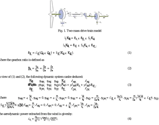
[image:3.612.47.564.250.657.2]An essential wind turbine system comprises of four noteworthy parts, i.e., wind turbine blades, gearbox and shaft, generator, and power converters. The wind vitality is caught through turbine cutting edges and changed over into mechanical torque. The generator changes the mechanical torque into power, which is passed on into the lattice after been balanced by the power converters. This paper concentrates on the demonstrating of the mechanical and streamlined parts, which considers complete measurements, for example, gearbox and shafts firmness, viscous protection, stacking impact, misfortunes, and so forth. To improve the displaying and investigation, it is expected that the gearbox, which fills in as a transmission segment, is firm and the attributes of wind turbine system won't change in a limited time. In addition, a two-mass model is embraced in this paper which is reasonable for control outline. Fig. 1 demonstrates the basic model of such transmission system [20]. The rotator and low-speed shaft is displayed by a rotational snapshot of latency Jr, two viscous damper with damping steady Br and Bls separately and a spring which speaks to shaft solidness Kls. The generator and fast shaft is displayed by a rotational snapshot of latency Jg, and a viscous damper with damping consistent Bg. The gearbox is displayed by a gearbox proportion ng, which should be flawlessly solid. The scientific model in Fig. 1 is depicted by the accompanying differential conditions:
Fig. 1. Two-mass drive train model
̇ = − − ,
̇ = − − ,
= ( − ) + ( − ), (1)
Where the gearbox ratio is defined as
= = = (2)
In view of (1) and (2), the following dynamic system canbe deduced:
̇
̇
̇
= + + , (3)
Where =− , = 0, =− , = 0, =− , = , = − , = − , =
− = , = 0, = 0, =− , = , =
The aerodynamic power extracted from the wind is givenby:
= ( , ), (4)
Where ( , ) is a nonlinear power coefficient which dependson the fixed blade pitch angle _ and the tip speed ratio _. Itcan be
represented as follows:
( , ) = − − + (5)
=
. −
.
. (6)
The power coefficient bend ( , )regarding and is appeared in Fig. 2. It demonstrates that for a settled pitch angle, there is a one
of a kind pick which can prompt an exceptional greatest esteem.
The torque delivered by the turbine can be ascertained as
= = ( , ) (7)
III. CONTROL OBJECTIVES
Control catch of Variable Speed Wind Turbine (VSWT), i.e., acquire the ideal power coefficient ( , ), the edge pitch point
ought to be settled at its ideal esteem right off the bat, and the rotor speed !t ought to be balanced by wind speed, in order to keep the tip speed proportion at the ideal esteem _opt. In this way, the rotor speed ought to be changed in accordance with tract the accompanying ideal esteem:
= , (8)
where R is the rotor span, and _opt is set to 7.5 with the end goal that the greatest productivity is accomplished, as appeared in Fig. 2. Another control objective is to decrease the loads put together by the drive prepare shaft which guarantees a low rate of progress of reference info and control. Something else, the mechanical structure falls behind the control flag, which prompts a high hazard and also low effectiveness.
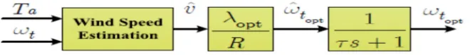
[image:4.612.149.479.419.458.2]The time reactions of the electric system are significantly quicker than different parts of the wind turbine, which makes it conceivable to separate the generator and the aero turbine parts [5]. Regularly, a course control structure is embraced, which comprises of two circles. The inward control circle intends to direct the
Fig. 3. Wind speed estimation scheme
generator current to its ideal esteem while the external control circle plans to drive the rotor speed to its reference an incentive and give the reference current of the inward loop. Given that the control system of inward circle has just been entrenched. Accordingly, this paper will just concentrate on the external circle outline under the presumption that the generator current is all around controlled.
IV. WIND SPEED ESTIMATION
To get the reference contribution to the external circle, i.e., the ideal rotor speed, the viable wind speed is required, which is hard to gauge straightforwardly. Accordingly in this paper the viable wind speed is assessed from the accessible factors, i.e. the rotor speed and turbine torque utilizing three numerical calculations. The streamlined torque can be effortlessly and similarly accurately measured. It can be depicted as
= ( , ), (9)
Where
( , ) = ( , ) (10)
creates a worthy yield. The rearranged Newton calculation is an amended calculation in light of the previous one, which streamlines the programming and lessen the operation time. The settled point emphasis strategy lessens the quantity of emphasess. The auto-seek technique utilizes a wrapped capacity in Matlab programming and is extremely advantageous. The numerical outcomes are comparative. Fig. 3 delineates the plan of successful wind speed estimation. The hysteresis components work is viewed as a channel keeping in mind the end goal to satisfy the second control objective.
V. FUZZY LOGIC CONTROL
The piece chart of MPPT control system is appeared in Fig. 4(a). In the square chart, the !topt and iqopt are the reference estimation of rotor speed and generator current individually, while the !t and iq are the estimation esteem got from the wind turbine system. This is a two-loop control system: The inward circle means to track the ideal generator current which diminishes responsive power to direct the power coefficient. Since numerous different works consider the electrical part control and the electrical change speed is quick, it is sensible to make the supposition that the internal circle is all around controlled [5]. The external circle means to track the ideal rotor speed reference given by !topt = _opt R ^v so as to augment the power removed from wind. In the condition, ^v is the gauge of wind speed. Considering the nonlinear idea of wind turbine system, the exceedingly aggravated work condition and additionally the error of scientific models, a controller in view of fuzzy rationale is proposed as takes after:
( ) = ( −1) +∆ ( ), (11)
and z-transformation is done by
( )(1− ) =∆ ( ), (12)
( )
∆ ( )= = (13)
The instrument of the fuzzy controller is appeared in Fig. 4(b). The info factors of the fuzzy controller are the rotor speed's error e and the difference in the mistake e_ while the yield _u is in increase shape. The reconciliation of the augmentation is the reference contribution of the internal loop.
Fig. 4. (a) MPPT control system with fuzzy logic controller, (b) Structureof fuzzy logic controller
The fuzzy controller comprises of four sections: fuzzification, fuzzy run base, surmising motor and defuzzification [2], [8]. The genuine estimation of the mistake e, the difference in the blunder e_ and the yield _u are on the whole fuzzily divided into fuzzy sets
These universes of talk can be balanced on the premise of the controller execution by the scaling factors as appeared in Table.I.
TABLE .I
Fig. 4(a). Moreover, considering the qualities of wind turbine, triangular participation capacities which are awry to give greater affectability as the factors approach zero are picked. Especially, the triangle enrollment elements of all the three signs have no cover keeping in mind the end goal to streamline the controller. The participation capacities ought not be set to zero at the area of unique to block yield no man's land. The parameters of the participation capacity ought to be somewhat balanced so as to enhance the controller's execution. To satisfy the control target that the estimation esteem it track the ideal reference rotor speed Wopt , the accompanying fifty-six fuzzy surmising rules are embraced as represented in Table I. In this fuzzy rationale controller, the surmising technique utilized is least and the defuzzication utilized depends on the focal point of gravity strategy.
VI. AN ADAPTIVENEURO-FUZZY INFERENCE SYSTEM
A adaptive neuro-fuzzy derivation framework or versatile system based fuzzy deduction framework (ANFIS) is a sort of counterfeit neural system that depends on Takagi–Sugeno fuzzy induction framework. The strategy was produced in the mid 1990s. Since it coordinates both neural systems and fuzzy rationale standards, it can possibly catch the advantages of both in a solitary structure. Its induction framework compares to an arrangement of fuzzy IF–THEN decides that have learning capacity to inexact nonlinear capacities. Thus, ANFIS is thought to be an all inclusive estimator. For utilizing the ANFIS as a part of a more productive and ideal way, one can utilize the best parameters acquired by hereditary calculation. ANFIS: Artificial Neuro-Fuzzy Inference Systems
A. ANFIS are a class of adaptive networks that are functionally equivalent to fuzzy inference systems.
B. ANFIS represent Sugeno e Tsukamoto fuzzy models.
C. ANFIS uses a hybrid learning algorithm.
In the field of artificial intelligence neuro-fuzzy alludes to mixes of fake neural systems and fuzzy rationale. Neuro-fuzzy hybridization brings about a half and half astute framework that synergizes these two procedures by joining the human-like thinking style of fuzzy frameworks with the learning and connectionist structure of neural systems. Neuro-fuzzy hybridization is generally named as Fuzzy Neural Network (FNN) or Neuro-Fuzzy System (NFS) in the writing. Neuro-fuzzy framework (the more mainstream term is utilized from this time forward) fuses the human-like thinking style of fuzzy frameworks using fuzzy sets and a semantic model comprising of an arrangement of IF-THEN fuzzy standards. The primary quality of neuro-fuzzy frameworks is that they are widespread approximates with the capacity to request interpretable IF-THEN principles.
ANFIS rules and membership functions
TABLE.II
∆e
e N Z P
N P P Z
Z P Z N
[image:6.612.204.407.615.729.2]Here; e is error : N, Z, P ; ∆ is change in error : N, Z, P; ∆ is output : N, Z, P
Membership function names are N is negative , Z is zero and P is positive to improve control precision as the variables approach zero.
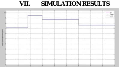
[image:7.612.208.408.130.242.2]VII. SIMULATION RESULTS
[image:7.612.172.441.272.400.2]Fig. 5. Wind speed estimations of ANFIS, FLC and PI control
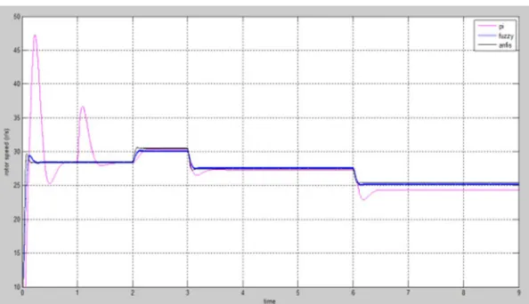
Fig. 6. Optimal rotor speed tracking of ANFIS, FLC and PI control
Fig. 7. Turbine power captures of ANFIS, FLC and PI controller
[image:7.612.194.414.435.561.2] [image:7.612.199.412.594.711.2]Fig. 9. Actual power coefficients of ANFIS, FLC and PI control
Fig. 10. Low-speed shaft torques of ANFIS, FLC and PI control
Fig. 11. Optimal rotor speed tracking of ANFIS, FLC and PI control under parametricuncertainties.
VII. CONCLUSION
[image:8.612.158.455.451.622.2]REFERENCES
[1] Romero-Cadaval, G. Spagnuolo, L. G. Franquelo, C.-A. Ramos-Paja,T. Suntio, and W.-M. Xiao, “Grid-connected photovoltaic generationplants components and operation,” IEEE Industrial Electronics Magazine,vol. 7, no. 3, pp. 6–20, Sept. 2013.
[2] X. Su, P. Shi, L. Wu, and Y. D. Song, “A novel control design ondiscrete-time takagi-sugeno fuzzy systems with time-varying delays,”IEEE Transactions on Fuzzy Systems, vol. 21, no. 4, pp. 655–671, Aug2013.
[3] X. Su, H. Zhou, and Y. D. Song, “An optimal divisioning technique tostabilization synthesis of T-S fuzzy delayed systems,” IEEE Transactionson Cybernetics, vol. PP, no. 99, pp. 1–10, 2016.
[4] M. N. Soltani, T. Knudsen, M. Svenstrup, R. Wisniewski, P. Brath,R. Ortega, and K. Johnson, “Estimation of rotor effective wind speed A comparison,” IEEE Transactions on Control Systems Technology,vol. 21, no. 4, pp. 1155–1167, 2013
[5] B. Boukhezzar and H. Siguerdidjane, “Comparison between linear andnonlinear control strategies for variable speed wind turbines,” ControlEngineering Practice, vol. 18, no. 12, pp. 1357–1368, 2010.
[6] B. Beltran, M. E. H. Benbouzid, and T. Ahmed-Ali, “Second-ordersliding mode control of a doubly fed induction generator driven windturbine,” IEEE Transactions on Energy Conversion, vol. 27, no. 2, pp.261–269, 2012.
[7] A. Levant, “Higher-order sliding modes, differentiation and outputfeedbackcontrol,” International Journal of Control, vol. 76, no. 9-10,pp. 924–941, 2003. [8] X. Su, P. Shi, L. Wu, and Y. D. Song, “A novel approach to filterdesign for T-S fuzzy discrete-time systems with time-varying delay,”IEEE Transactions on
Fuzzy Systems, vol. 20, no. 6, pp. 1114–1129,Dec 2012.
AUTHOR’S PROFILE