2018 3rd International Conference on Information Technology and Industrial Automation (ICITIA 2018) ISBN: 978-1-60595-607-7
A New Method to Design Power Meter Based
on GMR Sensor
Liuyuan Zhou, Wenli Chen, Zhihong Fu and Fuping Zhao
ABSTRACT
This paper presents a new method to design power meter based on giant magneto resistance (GMR) sensor. Firstly, we introduce the basic principle and characteristics of GMR sensor, and then propose an open-loop current sensor structure. The power of the circuit is transformed into the product of magnetic field around the GMR sensor and supply voltage of the sensor. According to the output voltage value of the sensor, we can calculate the power of the circuit. Finally, the output voltage of the sensor is collected by the AD sampling chip, converted into digital signal and then transmitted to the single chip computer for conversion. The instantaneous power value of the circuit is displayed on the display device. The designed power meter can measure signals from DC to high frequency (MHz magnitude), and the test method is simple.1
INTRODUCTION
Under the background of the global energy interconnection, smart grid has become an important research topic in the global energy development, and it is the development trend of the future power grid [1]. Insmartgrid, advanced sensor and measurement technology is the basis of monitoring, analysis and decision-making. Power measurement is one of the key technologies of electrical measurement. At present, power measurement technology and theoretical research mainly focus on two traditional methods :time division (TDM) and digital sampling (DSM) power
1
Liuyuan Zhou, Zhihong Fu, State Key Laboratory of Power Transmission Equipment & System Security and New Technology, Chongqing University
measurement technology, but both methods have their own shortcomings. This paper proposes a power measurement method based on GMR sensor, aiming at providing a new idea and scheme for the field of power measurement [2].
GMR effect refers to the phenomena that the resistivity of ferromagnetic materials such as iron, cobalt and nickel changes a lot in the magnetic field. It has developed rapidly since the 1980s. GMR effect has shown good application prospects in many fields, such as magnetic storage, compass, weak magnetic measurement, biomedicine, current measurement and other fields. Compared with traditional magnetic sensors or current sensors, sensors based on GMR effect have many advantages, such as small size, high sensitivity, high precision, wide measurement range, low cost, and can measure DC and AC signals.
PRINCIPLE OF GMR SENSOR
GMR Current Sensor
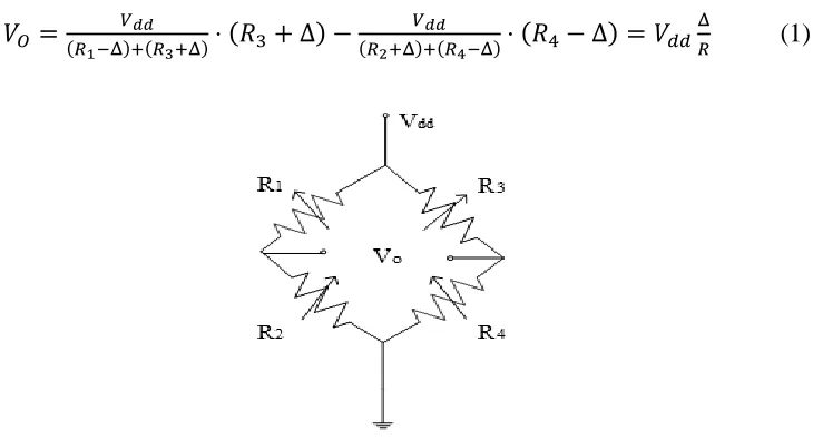
When measuring current by GMR materials, four GMR materials with identical characteristics are often connected into a Wheatstone bridge structure and encapsulated in an integrated chip. The structure can transform the change of magnetic field strength into output voltage. At the same time, the temperature drift characteristics can be effectively improved because the four GMR materials have the same characteristics. Figure 1 shows the internal structure of the bipolar GMR chip with full bridge, the resistance values of R1~R4 are R. When magnetic field is applied, the resistance of R1andR4, R2and R3 varies in opposite directions [3].
If voltage is applied between 𝑉𝑑𝑑 and ground, the output voltage 𝑉𝑂 represents
current information related to magnetic field information, thus,
𝑉𝑂 = 𝑉𝑑𝑑
(𝑅1−Δ)+(𝑅3+Δ)⋅ (𝑅3+ Δ) −
𝑉𝑑𝑑
(𝑅2+Δ)+(𝑅4−Δ)⋅ (𝑅4− Δ) = 𝑉𝑑𝑑
Δ
[image:2.612.131.496.459.656.2]𝑅 (1)
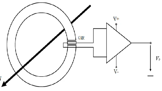
Figure 2. Schematic diagram for the GMR current sensor with an open magnetic ring.
In the formula, 𝛥indicates the change of resistance. When a magnetic field is applied in the opposite direction, the voltage output is -𝑉𝑑𝑑 ⋅𝛥𝑅. The output voltage of
bipolar GMR chip can not only reflect the strength of magnetic field, but also reflect the direction of magnetic field.
Design GMR Current Sensor
Figure 2 shows the schematic diagram for the GMR current sensor. Because the GMR current sensor is sensitive to the wire position, angle, interference current, magnetic field around and other factors, in practical use, an open magnetic ring with high permeability is used. The conductor to be measured crosses the magnetic ring, the GMR chip is placed in the opening of the magnetic ring
When the current in the conductor changes, the magnetic field strength around the conductor changes, and the resistance of the GMR sensor changes, the chip transform the change of resistance into output voltage. While the magnetic field around the current-carrying wire is proportional to the current inside the conductor, and the output voltage of the sensor is linear with the magnetic field around it, the magnitude and direction of the current inside the conductor can be calculated according to the output voltage of the sensor [4].
DESIGN GMR POWER METER
Overall Scheme
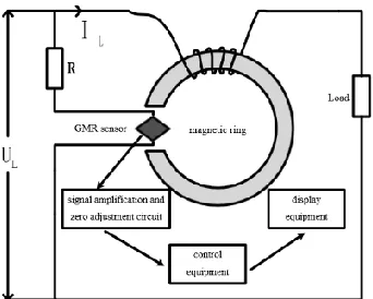
Figure 3. Principle of power meter.
The power meter is composed of divider resistance, open magnetic ring, GMR sensor chip, signal amplification and zero adjustment circuit, control equipment and display equipment. The divider resistance and the GMR sensor are connected to both ends of the power supply in parallel. The magnetic ring gathers the magnetic field generated by the load wire wound around the magnetic ring and the GMR sensor changes the magnetic field intensity to the output voltage. Signal amplification circuit is designed to amply the output voltage of GMR sensor and zero adjustment circuit to offset the inherent output voltage bias due to manufacturing process and other reasons. The processed data is sampled by the control equipment and converted into real power value, and then sent to the display equipment for display.
Principle of GMR Power Meter
The divider resistance and the GMR sensor are connected to both ends of the power supply in parallel, so the working voltage U1 of the sensor is
U1 = k1 ∙ UL (2)
where k1 is the voltage proportional coefficient and 𝑈𝐿isthe voltage of the load.
In this design, the magnetic ring gathers the magnetic field generated by the load current according to the Ampere circuital theorem, we can conclude that:
∮ Hdl = H1⋅ (2πr0− d) + H2⋅ d = NIL (3)
In the formula, 𝐻1is the magnetic field intensity in the magnetic ring, 𝐻2is the
magnetic field intensity in the air gap, 𝑟0is the average radius of the magnetic ring,
𝑰𝑳is the measured current and 𝑑 is the air gap width of the magnetic ring.
B = μμ0
2πr0μ0+(μ−μ0)dNIL=
μ0
d NIL = k2 ⋅ IL (4)
where 𝑘2 is the proportional coefficient of the magnetic field around the GMR current sensor and the magnitude of the load conductor current.
According to the characteristics of GMR current sensor, it can be concluded that the output voltage of GMR current sensor is proportional to the current of load wire. At the same time, according to the internal circuit structure of GMR sensor, Wheatstone bridge structure is adopted in the sensor, and its output voltage is proportional to the supply voltage. In conclusion, the output voltage 𝑈 of the GMR sensor is proportional to the current 𝐼𝐿 and the supply voltage 𝑈𝐿, that is,
U = k ⋅ UL⋅ IL= k ⋅ P (5)
where k is proportional coefficient. It can be seen that the output voltage 𝑈 of the GMR sensor is proportional to the electric power of the circuit, and the output voltage of the sensor can reflect the electric power of the current [5].
CIRCUIT DESIGN
Amplifying and Zeroing Circuit
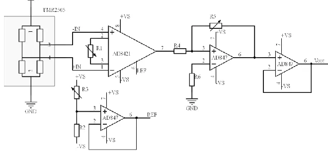
[image:5.612.138.468.485.639.2]The output voltage of the GMR chip is mV level, which will bring great errors in direct measurement, so the signal amplification circuit is designed to amplify the sensor signal to V level. Moreover, due to the limitation of production process and other conditions, the chip has inherent output bias, so the signal nulling circuit is added to compensate the output bias. Figure 4 shows the system circuit diagram.
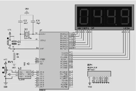
Figure 5. Sampling and processing circuit.
Sampling and Processing Circuit
The sampling and processing circuit is composed of a single chip computer as the control core, and an A/D conversion circuit and a digital tube display circuit. The main control circuit of single-chip computer adopts 51 series single-chip computer, which mainly completes the timing control and operation function of peripheral circuit, the digital tube display circuit completes the digital display function, the A/D conversion circuit realizes A/D conversion by A/D chip TLC549, TLC549converts the output analog voltage signal of amplification zero-setting circuit into digital signal. The circuit diagram is shown as Figure 5.
REFERENCES
1. Yixin Yu. Intelli-D-Grid for the 21stCentury [J]. Southern Power System Technology, 2006, 2(6): 14-16.
2. R.S. Turgel. Digital Wattmeter Using Sampling Method [Z]. IEEE Transition On Instrumentation and Measurement. 1974, IM-23(4):337-441.
3. Inman, D.J. 1998. “Smart Structures Solutions to Vibration Problems,” in International Conference on Noise and Vibration Engineering, C. W. Jefford, K. L. Reinhart, and L. S. Shield, Eds. Amsterdam: Elsevier, pp. 79-83.
4. Margarit, K. L. and F. Y. Sanford. March 1993. “Basic Technology of Intelligent Systems,” Fourth Progress Report, Department of Smart Materials, Virginia Polytechnic Institute and State University, Blacksburg.