Hardware Acceleration of Histogram Equalization and
Image Sharpening Filter on NIOS-II Processor based
SOC on FPGA
Ramakrishna.M
Department Of ECE Sri Vasavi Engg College
Tadepalligudem A.P, India 534101
Kishore Kumar.M
Associate Professor Department Of ECE Sri Vasavi Engg College
Tadepalligudem A. P, India 534101
Addanki Purna Ramesh
Associate Professor Department Of ECE Sri Vasavi Engg College
Tadepalligudem A.P, India 534101
ABSTRACT
In this paper, we presents a framework for hardware accelerating methods for video post processing system implemented on FPGA. The histogram equalization and image-sharpening filter are the algorithms ported onto the SOC having Altera NIOS-II soft processor. Custom instructions are chosen by identifying the most frequently used tasks in the algorithm and the instruction set of NIOS-II processor has been extended. Saturation and the Histogram are the new instructions added to the processor that are implemented in hardware and interfaced to the NIOS-II processor. The software implementation of the algorithms has been modified to use the new instructions added for computing the saturation and histogram calculation. Performance of the software implementation of the histogram equalization and sharpening algorithms is boosted by these new instructions added to the NIOS-II processor. The comparison shows that the implemented tasks have been accelerated by ―multiple‖ times. The saturation instruction is generic instruction, which can be used in many Image processing applications. The benefit of speed is obtained at the cost of very small hardware resources.
Keywords
Histogram equalization, SOC, NIOS-II soft processor, FPGA
1. INTRODUCTION
FPGA (Field Programmable Gate Arrays) are becoming more and more popular with their increased speedup with the new transistor technology. Their programmability gives the user to port various architectures onto the same device. At the same time tools likes ALTERA SOPC (System on Programming Chip) builder and NIOS-II soft processor eases the system development and NIOS-II IDE give software development environment. Fine grain acceleration of algorithms is a classic approach to accelerate the algorithms that requires high processing requirement. In fine grain, acceleration technique the small parts of the algorithm, which will be executed multiple times there by contributing good amount of final processing requirement will be identified and these algorithm sections will be accelerated by keeping dedicated hardware. This hardware will be activated by extended instructions of the processor. These instructions
provided simple way of adding the custom instructions to the NIOS-II soft processor and the NIOS-II IDE provides easy way of providing the software interface to the custom instruction added to the NIOS-II processor.
Image Post Processing Algorithms are playing crucial role with the emerging new TV technologies. The quality of the video witnessed by the consumers is crucial in TV market. Similarly, in medical applications, various image post-processing algorithms will be used to enhance the video captured by the camera sent into the body parts. And these video/image Post-processing algorithms requires huge amount of processing requirements with the increase of the resolution of the images like High Definition Resolution. An HD image has 1920x1080x3= 6.23 M Pixels. And the industry standard frame rate widely accepted is 30 fps. That means 187 M Pixels have to be processed in one second. This means the video post processing system running at 300 MHz frequency (The high frequency systems will suffer from the high power consuming there by less battery life) gets just 1.6 cycles to process one pixel. Hardwired architectures, which especially designed for particular algorithms, can achieve this kind of processing requirements but they lack flexibility and cannot be changed with the change in algorithms. Whereas processor based System on Chips gives enough flexibility to cope up with the change in algorithms but their programmable nature will not give the performance requirements like above. Therefore, identifying application specific custom instruction blocks to accelerate the ported image post-processing algorithm onto the processor, based SOC will be a good choice.
2. ALGORITHMIC BACKGROUND
2.1 Histogram Equalization
brightness enhancement, chrominance enhancement, etc [6]. Image enhancement also increases the difference between the object and the background. Thus, knowing the purpose of the image is important because making the right decision for which techniques to use is required [2]. The techniques in this research are based on the past research [2, 3] which can be defined as the function below [1, 11], respectively.
𝑆𝑘 = 𝑇(𝑟𝑘) = 𝑝𝑟(𝑟𝑓)
𝑘
𝑗 =0 (1)
𝑆𝑘 = 𝑛𝑓
𝑁; K = 0,1,2 … … L − 1 𝑘
𝑗 =0 (2)
Where is the output of histogram equalization?
𝑛𝑓 Is the number of pixels with the grey level j|j=0, 1, 2….L-1
N is the total number of pixels
𝑇(𝑟𝑘)is the transformation function of grey level at output
―η‖
𝑝𝑟(𝑟𝑗 )is probability of the grey level at input level ―η‖
A histogram is an illustration of the images statistical data. It demonstrates the frequency of which the amount of pixels at one part of the gray scale represents its characteristic. This process distributes suitable brightness for the sharpness of the image. The histogram of an image explains its characteristic towards the image, the contrast, the sharpness, etc., which is indeed present in every image.
2.2. Sharpening Filter
This filter enhances either the brightness of the image or the blur of the image by increasing the resolution. In some cases, Laplacian is used for the better results. The process for image filtering would filter noise, as a consequently the output image has different characteristic from the input [7]. For the desired result the filtering processes enhances and attenuates some qualities of the image[10].However, the sharpening filter used in this research is shown in equations below [1] respectively.
Where f(x,y) is the original image. g(x,y) is sharpen image.
Placing the value of ∆2f(x,y)
g(x,y)=f(x+1,y)+f(x-1,y)+f(x,y+1)+f(x,y-1)-4f(x,y)—(4) Image filtering by applying the sharpening process results in a higher resolution image especially the edges of different objects. Laplacian filtering is a stage of image processing, convolution processes with template and image. Template is known for an n x m matrix of a numerical set in order to make a superimposed image at certain positions. The solution for a convolution process begins with setting the template T(x,y) an n x m size matrix. The image I(x,y) is set at n x m as well. The convolution process is as demonstrated below
n-1 m-1
I’(X,Y) = T*I = ∑ ∑ T(i,j).I(X-i,Y-i) ---- (5) i=0 j=0
Where I’(x,y) is output image which is developed by convolution.
From equation (5), the DN value at (x,y) in the output image results from the total multiplication of the template with the DN value at the superimposed area of the image. The (x-i, y-j) shows that axis of the template flip over vertically and horizontally. Equation (6) demonstrates the convolution process without flipping over the template. This solution was known as ―Cross- correlation‖ one of the most popular solutions for image processing.
n-1 m-1
I’(X,Y) = T*I = ∑ ∑ T(i,j).I(X+i,Y+j) --- (6) i=0 j=0
Convolution was used in several ways for image processing such as, signal filtering, edge detection, or even analyzing the shape of the object in the image. In this research, convolution with laplacian is involved as the image filtering process. This process mainly detects edges with laplacian as show in the equation below.
∆2f=∂2f/∂x2+∂2f/∂y2
--- (7) Determine equation (7) by the x-axis ∂2f/∂x2
=f(x+1,y)+f(x-1,y)-2f(x,y) --- (8) Determine equation (7) by the y-axis ∂2f/∂y2=f(x,y+1)+f(x,y-1)-2f(x,y) --- (9) Placing the values of eq(8) and eq(9) in eq(7) ∆2
f=f(x+1,y)+f(x-1,y)+f(x,y+1)+f(x,y-1)-4f(x,y) (10)
Normally, the convolution process does not involve template sliding out of the edge of the image. Therefore, if the template size is more than 1x1, the output image would result in a smaller size than the original image. The solution is to enlarge the input image approximately one row and one column to all four sides. For the brightness value, fill in the number zero for the original image. Nevertheless, the disadvantage is the amount of time required for the calculation process is high.
3. SYSTEM BLOCK DIAGRAM
Figure 1: NIOS-II image processing system
final processed image into the SRAM. The intermediate pixel data is again stored in the SDRAM itself. The stack to hold all the variables is maintained in the SDRAM. The SRAM is used as frame buffer. From this frame buffer the final output pixels will be continuously read by the display controller and given to the VGA output meeting the timing requirements. The display controller also generates the HSYNC and VSYNC signals to the VGA DAC. The display process should not interrupted therefore the final images to be displayed are kept in SRAM which has low latency. Therefore, the system has two masters one is NIOS-II processor and the second is display controller. The switches are used to RESET the signal. The LEDs is used as checkpoints in the software execution for debug purpose. The JTAG UART peripheral are used by the NIOS-II IDE to execute standard printf commands. The custom instruction hardware will be explained detail description in the custom instruction section.
4. CUSTOM INSTRUCTIONS
The custom instructions identified to speed up the histogram equalization and the sharpening process is explained below.
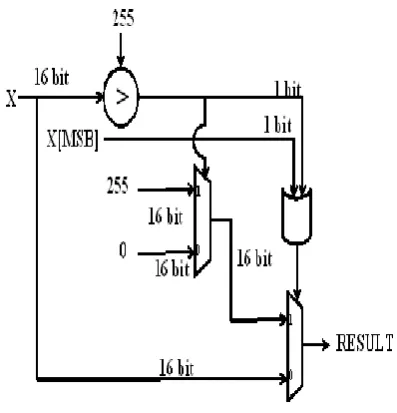
4.1 Saturation
Saturation arithmetic is a version of arithmetic in which all operations such as addition and multiplication are limited to a fixed range between a minimum and maximum value. If the result of an operation is greater than the maximum, it is set to the maximum while if it is below the minimum it is clamped to the minimum. The name comes from how the value becomes "saturated" once it reaches the extreme
and since the saturation operation has to be carried out one each pixel in the image, the number of cycles consumed for saturation is considerable. So the saturation is good choice for implementing as a custom instruction where we will compute the result in single cycle saving 8 cycles per each operation. SAT (P)is the custom instruction added to the NIOS-II processor which takes the filtered pixel P as input and limits its value between 0 and 255 and gives the result in the same and it is one of the custom instructions
Figure2: Saturation Custom Instruction Hardware
Q D En
start D Q
En
Q D En
n D Q
En (n == 3'b000)
start
1
0 0
(n == 3'b001)
Q Data In
Adder
1 Write_En
Histogram LUT
Q D En (n == 3'b001) start
dataa[7:0]
0
1
(n
_
2
d
=
=
3
'b
0
0
1
)
S
ta
rt
_
2
d
Start_2d
n_2d
[image:4.595.82.524.85.347.2]result
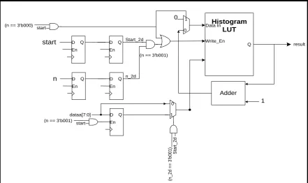
Figure 3: Histogram Computing Custom Instruction Hardware
Histogram Equalization process has three main steps. Clearing the histogram table, incrementing the histogram count at the location of the addressed by the pixel value in the histogram table and in the end compute the cumulative distribution function for the equalization process. A set of custom instructions added to the NIOS-II processor to speed up the histogram computation process. When implemented on NIOS-II processor without this custom instruction, the histogram table is maintained in the SDRAM. So read and write operations for clearing the histogram table and incrementing the histogram values and the complex register indirect addressing modes consumes lot of cycles. With the custom instruction provided for histogram, computation the histogram table is maintained as a RAM. One of the custom instructions is CLR_HIST (Addr) which clears the location of the histogram table RAM pointed by Addr. The second instruction is INC_HIST (Addr). This instruction reads the value pointed by Addr; increments it and write the result back to the same location. The third instruction is GET_HIST (Addr). Using this instruction, the histogram computed can be read from the histogram table by the NIOS-II processor for further processing. The micro architecture diagram for the histogram computation is shown in figure3.Here ―n‖ denotes the number of the custom instruction. The ―start‖
signal is the instruction valid signal. When the NIOS-II processor decodes one of the custom instructions, it asserts the ―start‖ signal and gives the appropriate ―n‖ value. Based on the ―n‖ value the custom instruction hardware gives the results back to the NIOS-II processor. CLR_HIST and GET_HIST take two cycles. As they do single, write and read operations respectively. The INC_HIST instruction is a four cycles as both read and write operations have to be performed in sequence.
4.3 VC++ Simulation Setup
The Visual Studio project has been created for simulating the histogram equalization and sharpening algorithms. Various images are given as input to get the histogram equalized and sharpened images as output
Figure 4: Histogram of the output image
[image:4.595.328.540.451.649.2]4.4 NIOS-II IDE Setup
The NIOS-II IDE is an embedded system software development tool provided by ALTERA. This IDE can be used to simulate the C code to be ported onto the NIOS-II system using Modelism and the C code can be dumped into the program memory of the NIOS-II processor so that the code can be directly run on the NIOS-II system on FPGA itself. The IDE should be used to replace the C-code correspond to the custom instruction with the custom instruction macros that can be defined by the built-in macros provided by the NIOS-II. The C code developed using the Visual Project as ported in NIOS-II IDE and first, the custom instruction C-code is replaced with the corresponding custom instruction macros. The figure shows the C-code they are replaced and its corresponding assembly code (assembly code without custom instructions) and the assembly code with custom instructions. With the help of this, we can calculate how many instructions can be replaced with the custom instruction thereby we can calculate the number of cycles saved assuming each NIOS-II instruction takes 1 cycle to be executed. The number of cycles actually taken be even more than 1 cycle per instruction depending on the type of the instruction, for example a load/store instruction issued SDRAM as target memory will take minimum 3 cycles. However, we assume the instructions are executed at a rate of 1 cycle/instruction that means the performance numbers we are quoting are the minimum performance improvement numbers whereas the actual improvement can be even more than the numbers we quote. The C code and the assembly codes with and without saturation custom instruction as shown in the figure.
5. IMAGE RESULTS
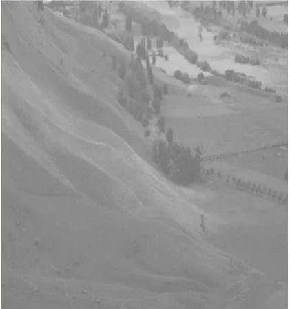
[image:5.595.331.538.71.245.2] [image:5.595.80.291.509.734.2]Various images are taken and tested on the Visual Studio setup and FPGA. A sample input and output images of the histogram equalization and sharpening process are given in figure 5. From the images, we can clearly observe that the distribution of the luminance is even in the processed image. In addition, the bad light in the original image has been corrected.
Figure 5: Original (top) and processed image
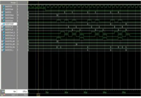
5.1 Simulation Results
To test the functionality of the custom instruction hardware, we have written Test bench in Verilog with the custom instruction hardware that computes saturation (or histogram computation) as DUT (Design under Test). The Test bench drives a series of test inputs to the DUT and is simulated using the Modelsim tool. The results are seen in the waveform and checked for correctness.The screenshots of waveforms as shown in figure 6 and figure 7.
5.2 Performance Comparison
5.2.1 Cycle Count Comparison
In this section of the paper, we give the details of the performance comparison of histogram clear, histogram computation and saturation functions when ported onto NIOS-II processor with and without the custom instructions. They are assumed that SDRAM memory access by load and store instructions takes minimum 3 cycles during the computation of this cycle estimations. From the table1 one can understand there is significant improvement with the custom instruction blocks.
Table 1: Histogram computation and saturation with and without the custom instructions
Criterion Without
Custom Instructio ns
with Custom Instructi ons
Histogram Clear per pixel level
18 1
Histogram Clear per QCIF frame
4.6K 256
Histogram Computation per pixel
57 1
Histogram Computation per QCIF frame
1.5M 25.3K
Saturation Computation per pixel
9 1
[image:5.595.333.548.568.757.2]Figure 6: Simulation results of saturation hardware
[image:6.595.80.549.408.735.2]The summary of the area, memory and IO pin utilization of the designed system ported on the Cyclone II FPGA EP2C20F484C7 as shown in table 2 and table3. The area utilization of saturation of custom instruction hardware is negligible. Therefore, it is not considerable
Table2: Area utilization of histogram computation without custom instruction hardware
Table: Area utilization of histogram computation custom instruction hardware
Resource Type Count
Total Logic Elements 63
Combinational 49
Logic Registers 14
Memory Bits 4864
IO Pins 0
6. CONCLUSION
This research represents the results the novel enhancement method and custom instruction method. Various types of images and instructions were testified on Nios-2 processor. The proposed method begins by contrast enhancement and speed up execution. This stage results in brightness production and decreasing the instruction cycles. Then, the sharpening process begins by subtracting then, the first stage-enhanced image with the edge. Moreover, custom instruction process is to begin the decreasing the instruction cycles and speed up the execution. The result indicates that this method performed best for only the main object in the image; the background show no change after the enhancement process was performs speedup execution. In conclusion, this novel method is suitable for these various types of images. The various images with several descriptions performed an accurate result after the enhancement process as done. However, it is best for the captured image to separate the object from the background and performed speed up execution.
7. REFERENCES
[1] Petcharat Pattanasethanon * and Boonwat Attachoo†,‖A Unified Histogram And Laplacian Based For Image Sharping ―IEEE International Conference(2009), June .1125-1130, 2009. Bangkok, Thailand.
[2] Boonwat Attachoo and Percharat Pattanasethanon, ―A New Approach for Colored Satellite Image Enhancement‖ IEEE International Conference on
Robotics and Biomimetics (IEEE ROBIO 2008), Feb. 22-25, 2009. Bangkok, Thailand
[3]Boonwat Attachoo and Petcharat Pattanasethanon,―Comparison of satellite image contrastenhancement‖, The 1st
Joint International Conference on Information Communication Technology (JICT 2007), 19-22 December 2007, Vientiane Lao PDR.
[4] K. S. Sim, ―Recursive sub-image Histogram Equalization applied to gray scale image,‖ Pattern recognition Letter, Vol.28, pp.1209-1221, 2007. [5] Zhiyu chen and etc. ―Gray Level Grouping (GLG):
AnAutomatic Method for Optimized Image Contrast Enhancement- Part I: The basic Method‖IEEE Transactions on image processing, vol.15 , August 2006, pp.2290-2302
[6]Takahiko Horiuchi, Kunio Watanabe, Shoji Tominaga,―Adaptive filtering for color image sharpening and denoising‖, Image Analysis and Processing Workshops, 2007. ICIAPW 2007, 14th International Conference on 10-13 Sept. 2007 Page196 – 201
[7] Winter, M.E.; Winter, E.M.; Beaven, S.G.; Ratkowski, A.J. ―Hyperspectral Image sharpening Using Multispectral data‖ IEEE - Aerospace Conference, 2007, 3-10 March 2007 Page(s):1 - 9
[8] Xing san, Hua Cai and Jiang Li, ―Color image coding by using inter color correlation‖, IEEE International Conference on Image Processing, 2006, 8-11 Oct. Page(s):3117 - 3120
[9] H.D. Cheng and X. J. Shi, ―A simple and Effective Histogram Equalization Approach to Image Enhancement‖,Digital Signal Processing, vol. 14, pp. 158-170, 2004
[10] Fabrizio Russo, ―An Image enhancement Technique combining sharpening and noise reduction‖ IEEE Transaction on instrumentation and measurement, Vol.51 No. 4, August 2002
[11]Toet A., ―Multiscale color image enhancement‖,IEEE, International Conference on Inage Processing and it Application,ICIP1992, Maastricht, Netherlands, 7-9, April, 1992
[12]Jonathan Parri, Miodrag Bolic&Voicu Groza ―Custom Instruction Hardware Integration within a SoC Hybrid Environment‖, 6th IEEE International Symposium on Applied Computational Intelligence and Informatics May 19–21, pp-517-522,2011 •
[13]ALTERA ―Introduction to the Altera NIOS –II Processor‖ www.ALTERA.COM
[14] ALTERA ―NIOS –II Processor Custom instruction user guide‖ www.ALTERA.COM
[15] ALTERA ―NIOS –II system architecture design tutorial‖ www.ALTERA.COM.
Resource Type Count
Total Logic Elements 6491
Combinational 3959
Logic Registers 4745
Memory Bits 97792