Obstacle Avoiding Robot
Trinayan Saharia1, Jyotika Bauri2, Mrs. Chayanika Bhagabati3 1,2
Student, 3Asst. Prof., ECE, Assam down town University, Assam
Abstract: An obstacle avoiding robot is an intelligent device, which can automatically sense and overcome obstacles on its path
and protect the robot from any physical damages.IR module is used to avoid the obstacle if obstacle comes on the front of the
IR module. Here NOT Gate IC is used as an inverter. The signal coming out from IR module is inverted by NOT Gate IC and the inverting signal is sent to the motor driver IC. Robot take the left or right or the forward movement in according to the sensing signal with the help of the two gear motor which makes the movement of the robot smooth.
Keywords: IR Module, Not Gate IC, L293D IC, 7805 IC, DC Motor
I. INTRODUCTION
Obstacle avoidance is one of the most important aspects of mobile robotics. Without it robot movement would be very restrictive and fragile. Obstacle Avoiding is a task which is used for detecting the objects placed in the path of the robot or any vehicle. Basically it's in the form of a moving vehicle which is able to detect and avoid potential obstacles on its path and change its direction appropriately so that its motion stays uninterrupted. The idea is simple and works without microcontroller . That means we can make it without any kind of coding and the circuit allows us to use any DC motor regardless of its power, so even high power obstacle avoiding vehicles could be made using this circuit which are normally used in malls and similar retail outlets.
II. COMPONENTS AND REQUIREMENTS
A . IR Module
It consists of IR Led, photo diode, resistors, 10K potentiometer , LM358IC
[image:2.612.236.378.402.530.2]1)IR Led:
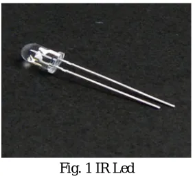
Fig. 1 IR Led
IR Led emits light, in the range of Infrared frequency. IR light is invisible to us as its wavelength (700nm – 1mm) is much higher than the visible light range. Everything which produce heat, emits infrared like for example our human body. Infrared have the same properties as visible light, like it can be focused, reflected and polarised like visible light.
2)Photo Diode:
Fig. 2 Photo diode
the current in reverse direction when Light falls on it, and the amount of current flow is proportional to the amount of Light. This property makes it useful for IR detection.
3)10 K Potentiometer:
Fig. 3 10K Potentiometer
A potentiometer, informally a pot, is a three-terminal resistor with a sliding or rotating contact that forms an adjustable voltage divider. If only two terminals are used, one end and the wiper, it acts as a variable resistor or rheostat.
[image:3.612.78.541.272.386.2]4) LM358 IC:
Fig. 4 Pin Diagram Fig. 5 LM358 IC
5)Pin Configuration of LM358 IC
The pin diagram of LM358 IC comprises of 8 pins, where
a) Pin-1 and pin-8 are o/p of the comparator
b) Pin-2 and pin-6 are inverting i/ps
c) Pin-3 and pin-5 are non inverting i/ps
d) Pin-4 is GND terminal
e) Pin-8 is VCC+
LM358 is an operational amplifier (Op-Amp) and in this circuit we are using it as a voltage comparator. The LM358 has two independent voltage comparators inside it, which can be powered by single PIN, so we can use the single IC to build two IR sensor modules. We have used only one comparator here, which have inputs at PIN 2 & 3 and output at PIN 1. Voltage comparator has two inputs, one is inverting input and second is non-inverting input (PIN 2 and 3 in LM358). When voltage at non-inverting input (+) is higher than the voltage at inverting input (-), then the output of comparator (PIN 1) is High. And if the voltage of inverting input (-) is higher than non-inverting end (+), then output is LOW.
[image:3.612.216.396.592.708.2]B. IC 7805
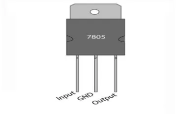
TABLE 1 Pin configuration
Pin No Function Name
1 Input voltage (5V-18V) Input
2 Ground (0V) Ground
3 Regulated output; 5V (4.8V-5.2V) Output
It is a voltage regulator IC. It converts high voltage (5V-18V) to low voltage(4.8V-5.2V).
[image:4.612.104.517.248.442.2]C. IC 7404
Fig. 7 Pin Diagram Fig. 8 7404 IC
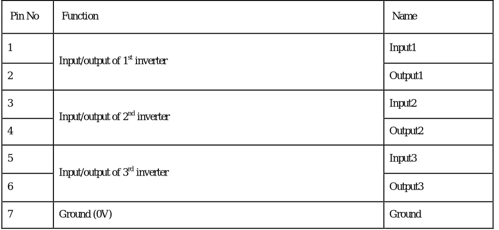
7404 is a NOT gate IC. It consists of six inverters which perform logical invert action. The output of an inverter is the complement
[image:4.612.63.553.511.737.2]of its input logic state, i.e., when input is high its output is low and vice versa.
TABLE 2 Pin Description
Pin No Function Name
1
Input/output of 1st inverter
Input1
2 Output1
3
Input/output of 2nd inverter
Input2
4 Output2
5
Input/output of 3rd inverter
Input3
6 Output3
8
Output/input of 4th inverter
Output4
9 Input4
10
Output/input of 5th inverter
Output5
11 Input5
12
Output/input of 6th inverter
Output6
13 Input6
14 Supply voltage; 5V (4.75 - 5.25 V) Vcc
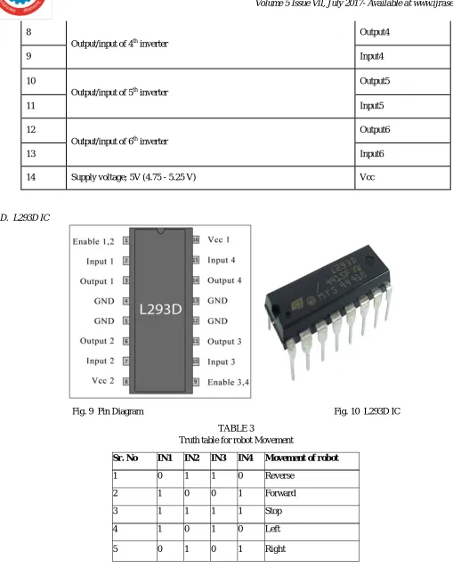
[image:5.612.41.550.53.691.2]D. L293D IC
[image:5.612.39.551.67.271.2]Fig. 9 Pin Diagram Fig. 10 L293D IC
TABLE 3
Truth table for robot Movement
Sr. No IN1 IN2 IN3 IN4 Movement of robot
1 0 1 1 0 Reverse
2 1 0 0 1 Forward
3 1 1 1 1 Stop
4 1 0 1 0 Left
5 0 1 0 1 Right
reverse direction. The motor operations of two motors can be controlled by input logic at pins 2 & 7 and 10 & 15. Input logic 00 or 11 will stop the corresponding motor. Logic 01 and 10 will rotate it in clockwise and anticlockwise directions, respectively. Enable pins 1 and 9 (corresponding to the two motors) must be high for motors to start operating. When an enable input is high, the associated driver gets enabled. As a result, the outputs become active and work in phase with their inputs. Similarly, when the enable input is low, that driver is disabled, and their outputs are off and in the high-impedance state.
[image:6.612.187.426.168.272.2]E. DC Gear Motor
Fig. 11 DC Gear Motor
Geared DC motors can be defined as an extension of DC motor. A geared DC Motor has a gear assembly attached to the motor. The speed of motor is counted in terms of rotations of the shaft per minute and is termed as RPM .The gear assembly helps in increasing the torque and reducing the speed. Using the correct combination of gears in a gear motor, its speed can be reduced to any desirable figure. This concept where gears reduce the speed of the vehicle but increase its torque is known as gear reduction.
F. LED
A light-emitting diode (LED) is a two-lead semiconductor light source. It is a p–n junction diode and it emits light whenactivated.
When a suitable voltage is applied to the leads, electrons are able to recombine with electron holes within the device, As a result, it releases energy in the form of photon.
G. Battery
The nine-volt battery, or 9-volt battery is used to backup the power. It has a rectangular prism shape with rounded edges and a polarized snap connector at the top.
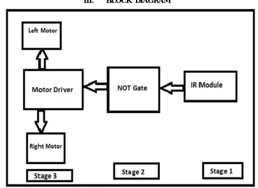
III. BLOCK DIAGRAM
[image:6.612.118.486.449.717.2]IV. WORKING PRINCIPLE
IR module is used to detect the obstacle if obstacle comes on the front of the IR module. The IR module send the signal to the 7404 IC or Not Gate IC. Here 7404 IC is used as an inverter. The signal coming out from IR module is inverted by 7404 IC and the inverting signal is sent to the motor driver IC L293D. Robot take the left or right or the forward movement in according to the sensing signal with the help of the two gear motor which makes the movement of the robot smooth.
[image:7.612.49.564.147.366.2]V. CIRCUIT DIAGRAM
Fig. 13 Circuit Diagram
VI. RESULT AND DISCUSSION
In IR Module we have used IR LED as a transmitter and Photo Diode as a receiver. It is used to detect the obstacle if obstacle comes on the front of the IR module. Here we have used NOT Gate as an inverter. The signal coming out from IR module is inverted by NOT Gate and the inverting signal is sent to the motor driver ic L293D. Robot take the left or right or the forward movement in according to the sensing signal with the help of the two gear motor which makes the movement of the robot.
VII. FUTURE SCOPE
In future, the sensing range can be increased by increasing the sensor quality with the help of ultrasonic sensor or the IR signal spread all over the provide area. Performance of this robot can be improved with the help of Bump sensors, for slow moving robots, Ultrasonic range sensors for large range up to 6m or LASER range finders. One of the prevailing fields is the use of camera in robot, Computer vision can be implemented for better performance.
VIII. CONCLUSION
From this study, a walking robot that achieved the stated objectives had been developed. This robot is able to produce the basic walking movements using two gear motors. We developed the robot with a very good intelligence which is easily capable to sense the obstacle and by processing the signal coming from the sensor, it is perfectly avoiding the obstacle coming in between the path Robot take the left or right or the forward movement in according to the sensing signal with the help of the two gear motor which makes the movement of the robot smooth .In future, the sensing range can be increased by increasing the sensor quality with the help of ultrasonic sensor or the IR signal spread all over the provide area.
REFERENCES
[1] http://www.engineersgarage.com/electronic_circuits. [2] http://www.electricaltechnology.com/motor_driverl293d
[3] “Obstacle Avoidance Robot” by K. Bhagt, S. Deshmukh, S. Dhonde, S. Ghag, V. Waghmare, IJSETR, Volume 5, Issue 2, February 2016, ISSN: 2278 – 7798, pp.439-442
[4] “OBSTACLE AVOIDING ROBOT – A PROMISING ONE” by R. Chandra Kumar, Md. S. Khan, D. Kumar, R. Birua, S. Mondal, M. Kr. Parai, IJAREEIE, Volume 2, Issue 4, April 2013, ISSN : 2278 – 8875, pp.1430-1434