Design and Analysis of Composite Truss Structure
for Space Borne Payloads
Shubham V. Rupani1, Shivang S. Jani2, Rahul Dev3 , Dr. G.D. Acharya4, Neeraj Mathur5
1
PG scholar, 2Assistant Professor, 4Principal , Atmiya Institute of Technology and Science, Rajkot.
3,5
Scientist/Engineer, Space Application Center, ISRO, Ahmedabad.
Abstract: Structure of space borne payload serves as load carrying member and is responsible to meet functional and stability requirement of various sensitive instruments. These structures need to survive launch loads and in orbit thermal expansions. When spacecraft is launched, it undergo excessive vibration and inertia forces. Hence designed mechanical structure should be stiff enough and natural frequency of the overall structure should not match with excitation frequency to avoid resonance. In this research work, structure configuration has been developed for payload. Most of the structure components are designed to be made of composite materials to minimize weight. Payload integration module is made from honeycomb sandwich panels and truss is made from carbon fiber reinforced polymer (CFRP) struts and metallic end fittings. Design considerations for laminate layup sequence has been discussed. Target Natural frequency of 50 Hz has been achieved. Structure for a space borne payload is deigned and analyzed in FEA tools.
Keywords: Mechanical structure, space borne payloads, composite, truss structure, FEA
I. INTRODUCTION
Space borne payloads are instruments or systems which are placed in spacecraft orbiting earth or other planet for remotes sensing and communication applications. These space operating systems undergo excessive loading conditions and temperature fluctuations while launching and in orbit operations. Hence materials used in space borne payloads should be able to withstand high stresses along with having thermal stability and light weight[1][2]. Imaging satellites are used to capture images of planets as well as earth for various applications. To capture clear images satellites must have minimum deflection of structural components and clean surfaces of optical reflectors.
Along with light weight metals, composite materials are now a days used in most space structures. Integration of metallic and composite materials can be done by various joining methods like mechanical fastening, adhesive bonding, welding etc.[3]. Among these methods adhesive bonding is most accepted method due to ease of application and low cost. Due to vacuum and high temperatures in space, materials tend to exhibit outgassing. Dissolved volatile contents present in polymer and adhesive materials tends to get evaporated and it may get deposited on reflector surfaces of mirrors. If it happens then it affects quality of captured data by optical sensors. Hence materials selected for space structure need to be qualified for space application. Outgassing limits for space qualification is such that total mass loss (TML) should be less than 1% and collected volatile condensable materials (CVCM) need to be less than 0.1% [4].
In certain applications where plate like structural members have buckling problem then honeycomb sandwich panels are used instead. Sandwich panels give high stiffness under compressive loading in axial direction of cells and facilitate fastening of instruments. Inserts are to be potted in honeycomb panel with adhesive to attach fasteners. Honeycomb sandwich structure consist of porous core sandwiched between metallic or composite face sheets. Face sheets are bonded with core by film adhesives[5]. Pressure is applied on face sheet by mechanical press or vacuum bagging. To achieve full strength, sandwich panel is then cured at either room temperature for around 7 days or at temperature around 80-120°C for one hour.
II. PRIMARY DESIGN OF STRUCTURE
Dynamic analysis is concerned with response of the structure under influence of external excitation. When spacecraft is launched from earth, the propulsion forces, acoustic and shock loads of space craft strongly interact with low to medium density dynamic characteristic of launch vehicle and will introduce mechanical vibrations throughout launch vehicle and spacecraft. The mechanical dynamic loads can be divided into two groups. One is low frequency sinusoidal vibration in domain of 2 Hz to 100 Hz. Another group is random vibrations in the range of 20 Hz to 2000 Hz[7]. Random vibrations can occur due to acoustic loads and boundary layer turbulences. Generally random vibration occur for very short period of time and hence essentially does not cause failure even if range of random vibration is more than first mode of natural frequency of structure.
Dynamic analysis also consist of checking mode shapes and damping characteristics along with values of natural frequency[8]. Mode shapes of oscillation can help to identify areas of components of the structure which have lower stiffness and need to be redesigned to achieve higher natural frequency of the overall structure. Damping characteristics can be ignored because damping in case of spacecraft structure is very low. For our application target frequency for overall structure is 50 Hz.
IV. MATERIAL SELECTION
[image:3.612.135.481.334.530.2]For truss structure to be used in space application major considerations are stiffness, thermal stability and weight. Based on these considerations, Fiber reinforced polymer (FRP) composites are now a days very popular for these applications. Comparison of metallic materials with FRP are given below.
Table 1: Material properties of metallic and FRP materials for space application[9]
Sr. No.
Material Density
(kg/m3)
Modulus (GPa) Tensile strength (MPa) CTE (μm/m°C)
1 Glass fiber 2100 45 1020 6.3
2 Aramid fiber 1380 76 1240 -4
3 Boron fiber 2000 210 1240 4.5
4 Carbon fiber 1580 145 1520 -0.9
5 Al6061 2680 68.2 320 23.6
6 Ti6Al4V 4430 114 900 8.8
7 Invar 8000 141 400 1.26
Although FRP materials are superior in mechanical properties but cannot be used for all the structural components because of difficult manufacturing of composite parts. Hence metallic materials has to be used in small and intricate parts. For Struts, carbon fiber reinforced polymer is the most suitable choice. Aluminum alloys, Titanium alloys and Invar are the most widely used metallic materials in space applications.
All the optical and electronic equipments are mounted on base plate of PIM box structure. These mounted instruments acts as lumped and concentrated mass. Hence base plate of PIM structure need to have very high stiffness in direction perpendicular to plate. For this requirement, honeycomb sandwich structure is used in all the panels of PIM box structure. All the brackets and connectors are made of Aluminum alloy to minimize overall weight of structure.
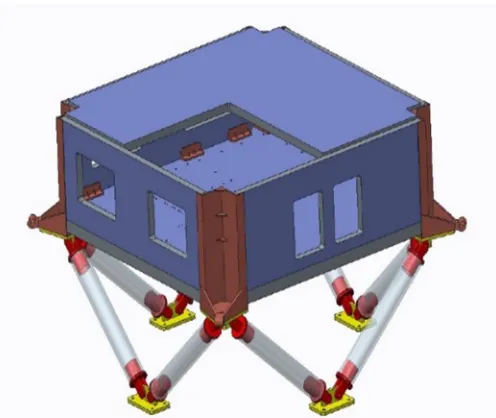
V. CAD MODELLING
Figure 1: CAD model of primary mechanical structure
Table 2: Materials selected for structural components
Sr. No. Component Material
1 PIM structure panels Al honeycomb core with Al face sheet
2 Brackets Al6061
3 Connector Al6061
4 Strut CFRP
For our application, space qualified high corrosion resistance honeycomb core CRIII-3/16-5056-0.0015-4.4P manufactured by Hexcel corporation is selected. Designation of core defines following parameters[10]:
CRIII – corrosion resistant honeycomb 3/16 – cell size in inches
5056 – Aluminum alloy 0.0015 – foil thickness
4.4 – density in pound per cubic feet P – Perforated core
Here perforated core is selected to allow gases to escape during curing from cell volumes.
Material property, fiber orientation and lamina thickness are required to define composite properties. Axial direction of tube is considered as reference direction and accordingly quasi-isotropic laminate has been defined.
VI. LAMINATE DESIGN CONSIDERATION
extension, shear, bending and torsional stiffness, laminate has to be defined with certain boundary conditions. Coupling effects and their remedies are as shown in table 3.
Table 3: Laminate design considerations[11]
Behavior Remedy
Bending Extension Coupling Symmetric laminate
Shear Extension Coupling Balanced Laminate
Bend Twist Coupling Increase Number of Lamina, Less number
of angle Plies
In our application, laminate is defined to be [0, 60, -60, -60, 60, 0]4s. Toray700S fiber is selected with Huntsman XB3542/Aradur5120 resin system[12]. Individual lamina thickness is taken as 0.17 mm which is minimum achievable thickness with selected material and fabric winding process.
Material properties of FRP composite is as follows. Tensile strength = 2550 MPa
Tensile modulus = 135 GPa Compressive strength = 1470 MPa Flexural strength = 1670 MPa Flexural modulus = 120 GPa
Transverse tensile strength = 69 MPa
Coefficient of thermal expansion = 4.8 μm/m°C
VII. BONDED JOINT DESIGN
Several methods are available for joining metallic parts with CFRP components. Major categories of dissimilar material joining methods are adhesive bonding, mechanical fastening and welding[3]. Among these three methods, adhesive bonding is most feasible and cheapest method of all for joining dissimilar materials in space application.
Figure 2: Adhesive bonded joint design
While selecting adhesive for space application environmental factors such as effect of vacuum and drastic temperature variations are need to be considered. Outgassing phenomenon is observed in vacuum. Outgassing is a measure of the level of residual low molecular weight species that can be evolved at elevated temperature. Low molecular weight volatile matter gets vaporized and it may get deposited on optical reflectors such as mirrors. This may cause interference in optical functioning of spectrometers. Adhesive to be used in space must qualify ASTM E595 outgassing standards[4]. Limits for qualifying ASTM E595 is TML should
CFRP strut
[image:5.612.160.403.473.634.2]be less than 1% and CVCM should be less than 0.1% by mass. For structural application epoxy based adhesive is widely used. Hysol EA9309 adhesive is selected based on technical specifications[13].
Shear area for bonded joint A = пdl = 7615 mm2
Here considering maximum load acting on baseplate of box structure to be 200 kg and in launching conditions maximum acceleration is 15g then axial load acting on one strut is 2325 N. Taking factor of safety of 2 for shear stress calculation,
τ = = = 0.61 MPa
Shear strength of adhesive at room temperature is 37.2 MPa and at temperature of 82°C shear strength is 6.9 MPa which is far greater than shear stress of 0.61 MPa[13]. Hence bonded joint will be safe.
VIII. MODAL ANALYSIS
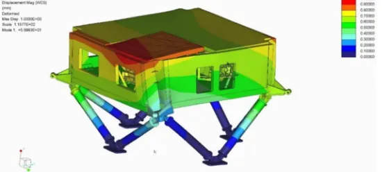
Modal analysis is performed in creo to find first mode of natural frequency. All the optical spectrometers are mounted on base plate and loads acting due to electronics are applied as lumped mass attached to rigid links. As shown in figure first mode is at 56 Hz which is more than target frequency of 50 Hz.
Figure 3: Mode shape for first Natural frequency of structure at 56 Hz
IX. STATIC ANALYSIS
[image:6.612.170.445.290.414.2]All the loads acting on the base plate are applied as lumped mass as shown in figure 4. Fixed constraint is applied on brackets at the end of struts. Static analysis is performed to check stresses acting on the structural components. Results are as shown in figure 5.
Figure 4: Loads acting on base plate Spectrometers (29kg) Electronics
Figure 5: Static analysis : (a) Von-mises stress (b) max. principal stress (C) max. shear stress
Maximum von-mises stress, maximum principal stress and maximum shear stresses are well below corresponding strengths of selected materials. Maximum von-mises stress is 56 MPa, maximum principal stress is 70 MPa and maximum shear stress is 30 MPa. These maximum stresses are acting at very localized regions and hence not visible as contours in result window
X. CONCLUSION
A summary of design criteria for space borne mechanical structure has been provided. Dynamic design considerations for designing of space borne structure are investigated. Primary design methodology and design considerations for FRP composites and honeycomb sandwich panels are discussed. Adhesive bonded circumferential lap joint is designed to join metallic connector with CFRP strut. CAD model is prepared and FEA is performed to find natural frequency and stresses acting on structural members. Natural frequency of 56 Hz has been achieved for overall structure.
XI. ACKNOWLEDGEMENT
REFERENCES
[1] M. An et al., “Research on the support truss structure of foreign space remote sensor with large-scale and flexibility,” Proc. SPIE - Int. Soc. Opt. Eng., vol. 9280, p. 92800Y, 2014.
[2] F. Zeng, J. Yang, and J. Wang, “Study on light weight design of truss structures of spacecrafts,” Remote Sens. Environ. 19th Natl. Symp. Remote Sens. China, vol. 9669, p. 966902, 2015
[3] P. Kah, R. Suoranta, J. Martikainen, and C. Magnus, “Techniques for Joining Dissimilar Materials: Metals and Polymers,” Adv. Mater. Sci, vol. 36, pp. 152– 164, 2014.
[4] K. Fayazbakhsh and A. Abedian, “Materials selection for applications in space environment considering outgassing phenomenon,” Adv. Sp. Res., vol. 45, no. 6, pp. 741–749, 2010.
[5] T. N. Bitzer, Honeycomb Technology. Springer Science+Business Media, 1997.
[6] N. C. Jessen, H. Norgaard-Nielsen, T. Stevenson, J. Sykes, J. Schroll, and H. Peter, “The CFRP primary structure of th
[7] MIRI instrument onboard the James Webb Space Telescope,” Astron. Struct. Mech. Technol., vol. 5495, pp. 1–8, 2004.J. Wijker, Mechanical Vibrations in Spacecraft Design, 1st ed. Springer, 2004.
[8] J. J. Wijker, Spacecraft Structures. Springer, 2008.
[9] P. Yoder, Opto-mechanical systems design, 4th ed. CRC Press, 2015. [10] “Honeycomb core data sheet,” 2015.
[11] R. M. Jones, Mechanics of composite materials, 2nd ed. Taylor and Francis, 1975 [12] “Toray 700S fiber technical datasheet.” [Online]. Available:
https://www.google.nl/url?sa=t&rct=j&q=&esrc=s&source=web&cd=1&cad=rja&uact=8&ved=0ahUKEwiZ4POYn_fSAhVFtBoKHWiMAdwQFggcMAA&u rl=http%3A%2F%2Fwww.toraycfa.com%2Fpdfs%2FT700SDataSheet.pdf&usg=AFQjCNFFjVWQv_HaFGCJtW7GVpnym3uPfg&sig2=hqorhqVB3rT7eOWt 2JMoQ
[13] “Loctite EA9309 Adhesive datasheet.” [Online]. Available:
![Table 1: Material properties of metallic and FRP materials for space application[9] Sr](https://thumb-us.123doks.com/thumbv2/123dok_us/8308317.857067/3.612.135.481.334.530/table-material-properties-metallic-frp-materials-space-application.webp)
![Table 3: Laminate design considerations[11]](https://thumb-us.123doks.com/thumbv2/123dok_us/8308317.857067/5.612.160.403.473.634/table-laminate-design-considerations.webp)