5
III
March 2017
Technology (IJRASET)
Automatic Pothole Detection System using Laser
S. Yamuna1, S. Raja2, Pavithra. M3, Ranjitha. M4, Shubashni. R5, Sneha. S6
1,2
Assistant Professor, 3,4,5,6UG Students , Dept. of ECE
Sri Shakthi Institute of Engg and Technology, Coimbatore, TN, India.
Abstract: Identification of pavement distress such as potholes and humps not only helps drivers to avoid accidents, but also helps authorities to maintain roads. This project discusses previous pothole detection methods that have been developed and proposes a cost-effective solution to identify the potholes and humps on rods and provide timely alerts to drivers to avoid accidents or vehicle damages. Lasers are used to identify the potholes and humps. The proposed system captures the geographical location coordinates of the potholes and humps. It can actively learn the knowledge about the suspension system of the host vehicle without any human intervention vibration model to infer the presence of pothole while the vehicle is hitting the pothole. As a proof of concept Raspberry Pi based prototype of proposed system is designed and going to be developed for small application. Keywords: maintained roads, cost-effective solution, geographical location, pothole.
I. INTRODUCTION
Roads are the dominant means of transportation today. They carry almost 90% of countries passenger traffic and 65% of its freight. Over the last 2 decades there has been a tremendous increase in the vehicle population. This proliferation of vehicles has led to problems such as traffic congestion and increase in the number of road accidents. Researchers are working in the area of traffic congestion control, an integral part of vehicular area networks, which is the need of the hour today. Roads in India normally have speed breakers so that the vehicle speed can be controlled to avoid accidents. Pothole is a bowl shaped depression in the pavement surface. Potholes can generate damages such as flat tire and sudden breaking and steering wheel operation, and vehicle collision and major accidents. It is an important clues indicating structural defects of the asphalt road and accurately detecting these potholes is one of the important tasks for determining proper strategies of asphalt- surface pavement maintenance. It works for the integral part of vehicular area networks. The Laser technology uses a technique that employs reflected laser pulses to create accurate digital models of existing objects. The accurate point with their elevations was captured during scanning and extracted focusing on specific distress features by means of a line-based processing approach. The experimental results indicate that the severity and coverage of distress such as potholes can be accurately and automatically quantified to calculate the needed amounts of filled materials. Laser technology can detect potholes in real time. The cost of laser scanning equipment is significant at vehicle-level and currently these works are focused on the local accuracy of 3D measurement.
II. LASER TECHNOLOGY
Technology (IJRASET)
Fig 1 Line Laser
III. RASPBERRY PI
The Raspberry pi is a low cost, credit-card sized computer that plugs into a computer monitor or TV and uses a standard keyboard and mouse. It is capable little device that enables people of all ages to explore computing, and to learn how to program in languages like Scratch and Python. It's capable of doing everything you had expect a desktop computer to do, from browsing the internet and playing high-definition video, to make spreadsheets, word-processing and playing games. The Raspberry Pi has the ability to interact with the outside world, and has been used in a wide array of digital maker projects, from music machines and parent detectors to weather stations and tweeting birdhouses with infra-red cameras. All Raspberry Pi include the same Video core IV Graphics Processing Unit (GPU), and either a single-core ARMv6-compatible CPU or a newer ARMv7-compatible quad-core one and 1GB of RAM, 512 MB or 256 MB. They have a Secure Digital (SDHC) slot or a Micro SDHC one for boot media and persistent storage. That new computer board is initially available only in one configuration (model B) and has a quad-core ARM Cortex-A7 CPU and 1GB of RAM with remaining specifications being similar to those of the prior generation model B+. In November 2015, the Foundation launched the Raspberry Pi Zero, a smaller product priced at US$5. Raspberry Pi 3 was released on 29 February 2016.
IV. OBJECTIVE
The main objective of this project is to sense and estimate the profiles of potholes on urban surface roads. The Image Processing technique used in this system will display the location of the pothole. This project is to identify the pavement distress such as potholes and humps. It also addresses poor condition of roads. The aim is to gather the severity information about the uneven road surfaces. This proposed method gives us an economic solution that also works in rainy season when potholes are filled with muddy water. The novelty of this system is the implementation of the controlling mechanism of appliances in different ways.
V. LITERATURESURVEY
Traffic Management on the road has become a severe problem of today's society because of growth of the urbanization, industrialization and population; there has been a tremendous growth in the traffic. With growth in traffic, there is occurrence of bundle of problems too; these problems include traffic jams, accidents and traffic rule violation at the heavy traffic signals. This in turn has an adverse effect on the economy of the country as well as the loss of lives. In this system we exploit the emergence of new technology called Intelligent Traffic Light Controller, this makes the use of sensor n/w along with embedded technology. Where traffic light will be intelligently decided based on the total traffic on all adjacent roads. Thus optimization of traffic light switching increases road capacity, traffic flow and can prevent traffic congestions. In this system, the first aim is to collect the information of moving emergency vehicles using GSM, GPS, ARM to provide them clear path. This system can do the following, i)Minimize long waiting time, ii) Achieve smart automatic traffic signal control without human interrupt, iii)Wirelessly monitor patient help parameter through GSM technology, iv) Less chance of accident due to red light violation it gives priority to vehicles like ambulance, fire brigade, VIP vehicles etc. The drawback is that it does not consider traffic signal and vehicle tradeoffs.
The high demand of automobiles has also increased traffic hazards under road accidents. This project will provide an optimum solution to this drawback. An accelerometer can be used in a car alarm application so that dangerous driving can be detected. It can be used as a crash or rollover detector of the vehicle during and after a crash. With signals from an accelerometer, a severe accident can be recognized. According to this project when a vehicle meets with an accident immediately. Vibration sensor will detect the signal or if a car rolls over, and Micro Electro Mechanical Systems (MEMS) sensor will detect the signal and sense it to ARM controller. Micro Controller sense the alert message through the GSM MODEM including the location to police control room or a rescue team. So the police can immediately trace the location through the GPS MODEM, after receiving the information. Then after conforming the location necessary action will be taken. If the person meets with the small accident or if there is no serious threat to any one's life, then the alert message can be terminated by the driver by a switch provided in order to avoid wasting the valuable time of the medical rescue team. This paper is useful in detecting the accident precisely by means of both vibration sensor and Micro Electro Mechanical System (MEMS) or accelerometer. The drawback of this project is that it does not investigate mechanism about provide driver's assistance.
. VI. EXISTING SYSTEM
Technology (IJRASET)
accidents, vehicle damages and also used to maintain the roads neatly. Ultrasonic sensor are used to identify the potholes and humps and also to measure their depth and height between vehicle and roads. Ultrasonic sensor which is front facing is used to identify the front vehicles within its range. Ultrasonic sensor which is rear facing detects backside vehicles and gives alert messages. The inclined sensor detects the holes and humps on roads. GPS (Global Positioning System) tracker is carried by vehicle and it provides the latitude and longitude of the vehicles position. Raspberry pi is the microprocessor unit, processing all the inputs and gives output through GSM and speaker. Global system for mobile (GSM) sense data of the sensors and GPS to mobile applications. Speaker provides the alert messages to the vehicle driver. This system automatically detects the holes or humps, Vehicles in front and rear and alerting the vehicle avoid the potential accidents.
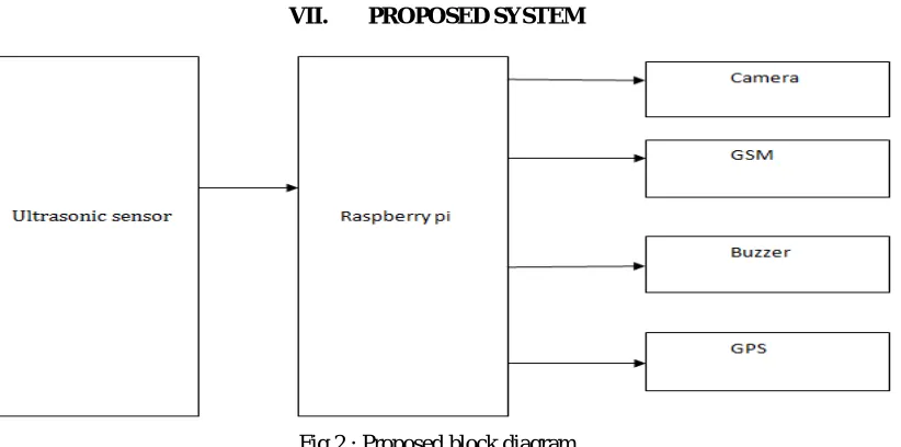
[image:4.612.107.518.193.397.2]VII. PROPOSED SYSTEM
Fig 2 : Proposed block diagram
This system has been designed for detection of potholes and humps to avoid accidents. Important function of the system are the sensing, controlling and output. Ultrasonic sensor are used to identify the potholes and humps and to measure their depth and height between vehicle and roads. Ultrasonic sensors which is front facing is used to identify the front vehicles within its range. The Sensor which is rear facing detects backside vehicles and gives alert messages. The inclined sensor detects the holes and humps on road. GPs tracker is carried by vehicle and it provides the latitude and longitude of the vehicle's location. Raspberry pi is microcontroller unit, processing all the inputs and gives output through GSM and speaker. GSM sends data of the sensors and GPs to mobile applications.
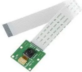
A. Camera
Technology (IJRASET)
GPs is a satellite navigation system and is used to capture geographic location and time, irrespective of weather conditions. It is maintained by the US government and is freely available to anyone who has a GPS receiver. It obtains the GPS information from the satellite in National Marine Electronic Association (NMEA) format. The NMEA has defined a standard format for the GPS information. This is followed by this GPS receiver gives data output in standard NMEA format with update rate of 1 second at 9600 bps. Receiver has on board battery for memory backup for quicker acquisition of GPS satellites. Module can directly work on 5V supply and can be interfaced with the 5V TTL/CMOS logic. Board has 10 pin male berg connected at the both ends for easier mounting on the PCB and comes with the 2 pin female berg connectors which can be soldered on your PCB. This GPS module is very easy to interface and requires only transmit, receive pins of the serial port of the microcontroller of all the satellites.
C. GSM
[image:5.612.239.370.264.379.2]GSM makes use of a narrow band time division multiple access (TDMA) technique for transmitting signals. GSM was developed using digital technology. It has an ability to carry 64kpbs to 120Mbps of data rates. Presently GSM supports more than one billion mobile subscribers in more than 210 countries throughout the world. GSM provides basic to advanced voice and data services including roaming service.
Fig 3: Raspberry Pi Camera.
D. Line Laser
A laser is a device that emits light through a process of optical communication based on the stimulated emission of electromagnetic radiation. A laser differs from other source of light in that it emits light coherently. In imaging science, image processing is processing of images using mathematical operations by using any form of signal processing for which the input is an image; the output of image processing may be either an image or a set of characteristics or parameters related to the image. Most image-processing techniques involve treating the image as a two-dimensional signal and applying standard signal-image-processing techniques to it. Images are also processed as three-dimensional signals with the third-dimension.
VIII. WORKING MODULE
A hardware module is a physical computing device that safeguards and manages digital keys for strong authentication and provides crypto processing. These modules traditionally come in the form of a plug-in card or an external device that attracts directly to a computer. Design hardware module may possess controls that provide tamper evidence such as logging and alerting. Many hardware module systems have means to securely backup the keys they handle either in a wrapped from via the computer's operating system or externally using a smartcard or some other security token.
A. Tracking Deviation Modules
The camera track the path, and display the image when there is any deviation in the road. Under this system the deviated image is viewed in more than one segment. K-means is one of the simplest unsupervised learning algorithms that solve the well-known clustering problem. The procedure follows a simple and easy way to classify a given data set through a certain number of clusters (assume k clusters) fixed a priori. The main idea is to define k centroids, one for each cluster. These centroids should be placed in a cunning way because of different location causes different result.
B. Controlling Module
Technology (IJRASET)
mechanically or by using a voltage (sometimes also current) signal over a cable. Typically embedded systems tend to have a lot of different cables with signals, coming with different locations, but going to a same controller. These controllers, on the other hand, only have a few control module ports. Control modules have a large number of (mostly digital) inputs and outputs, depending on the type. Communication between the control module and the controller occurs through one connection over which both the inputs and the outputs are sent. The control module does not change the signals on this connection, it only edits them (in a reversible way) such that they can be sent using only one connection depending on the type of control.
C. Output Module
Communication between the input output module and the controller occurs through one connection over which both the inputs and the outputs are sent. The input output module does not change the signals on this connection, it only edits them (in a reversible way) such that they can be sent using only one connection. Depending on the type of control module, the signals should first go through a ADC/DAC, before being passed on to the control module.
IX. RESULTS AND DISCUSSIONS
Fig 4: Proposed hardware module
Technology (IJRASET)
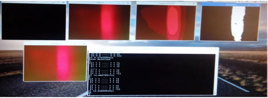
[image:7.612.62.517.100.267.2]Fig 5: Proposed system software module
Fig 6: Software output for path hole detection
X. CONCLUSION
A road monitoring and control system has been designed and developed toward the implementation of a transportation network. The developed system effectively detects and controls the humps and potholes. The system can be extended for controlling the road networks. The aim is to lower the cost consumption and enhance better utilization of already limited resources, in its size. The Laser are programmed with various user interfaces suitable for users of varying ability and for expert users such that the system can be maintained easily and interacted very simply. In Future, the system will be integrated to the government authorities by sending information about the unsafe of the road conditions, so that the irregular road surfaces will be get repaired periodically. It can also form the server database to the road transportation network and send received details through IOT (Internet of Things). This server database may help government to check the road conditions periodically.
REFERENCES
[1] Ghose A., Biswas P., Bhaumik C., Sharma M., Pal A., Jha A. Road condition monitoring and alert application: Using in-vehicle Smartphone as Internet-connected sensor; Proceedings of the 2012 IEEE International Conference on Pervasive Computing and Communications Workshops; Lugano, Switzerland. 19–23 March 2012; pp. 489–491.
[2] Mednis A., Strazdins G., Zviedris R., Kanonirs G., Selavo L. Real time pothole detection using Android smart phones with accelerometers; Proceedings of the International Conference on Distributed Computing in Sensor Systems and Workshops; Barcelona, Spain. 27–29 June 2011; pp. 1–6.
[3] S. Rode, S. Vijay, P. Goyal, P. Kulkarni, K. Arya, "Pothole Detection and Warning System: Infrastructure Support and System Design," International Conference on Electronic Computer Technology, pp.286-290,Feb. 2009.