Technology (IJRASET)
Simulation of Distributed Power Flow Controller
Mr. K. Prahlada Reddy, J. Vamsi Srinivas1, K. Vamsi Naidu2,K. P. Veeresh Rao3, K. Pakkirappa4, C. Ravindra Reddy5#
Department of EEE, G. Pullaiah College of Engineering and Technology
Abstract— The growing demand and the aging of networks make it desirable to control the power flow in power-transmission
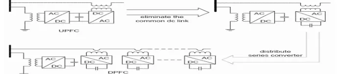
systems fast and reliably. The Load changes the voltage variation in transmission lines must be limited, otherwise the consumer’s equipments are damaged at distributed side. For reducing these types of problems to develop this controller. The DPFC (Distribute Power-Flow Controller) modified from UPFC for increasing system reliability and reducing costs. The Distributed Power Flow Controller (DPFC) is derived from the Unified power-flow controller (UPFC).The DPFC is a solution to control the power flow in a single transmission line. By eliminating the common DC link and distributing the three phase series converters of the UPFC, a new concept of the Distributed Power Flow Controller (DPFC) is achieved. The DPFC independently controlling the active and reactive power flow in transmission line. The DPFC employs the distributed FACTS (D-FACTS) concept, which is to use multiple small-size single-phase converters instead of the one large-size three-phase series converter in the UPFC. This consists of both active and reactive variations, using MATLAB/SIMULINK is simulated and its effects on the transmission lines observed. The simulated results are analyzed and validated with the real time results for the system considered.
.Keywords— DPFC, Transmission line parameters control, Power flow controller, third harmonic frequency
I. INTRODUCTION
Electricity has played an increasingly important role in our daily lives, with a dramatic increase in consumption as well as the generation of electricity over the past hundred years. The electrical power system serves to deliver electrical energy to consumers. An electrical power system deals with electrical generation, transmission, distribution and consumption. In a traditional power system, the electrical energy is generated by centralized power plants and flows to customers via the transmission and distribution network. The rate of the transported electrical energy within the lines of the power system is referred to as ‘Power Flow’, to be more specific, it is the active and reactive power that flows in the transmission lines. During the last twenty years, the operation of power systems has changed due to growing consumption, the development of new technology, the behaviour of the electricity market and the development of renewable energies.
With the rapid development of power electronics, Flexible AC Transmission Systems (FACTS) devices have been proposed and implemented in power systems. FACTS devices can be utilized to control power flow and enhance system stability. Particularly with the deregulation of the electricity market, there is an increasing interest in using FACTS devices in the operation and control of power systems with new loading and power flow conditions. A better utilization of the existing power systems to increase their capacities and controllability by installing FACTS devices becomes imperative. Due to the present situation, there are two main aspects that should be considered in using FACTS devices the first aspect is the flexible power system operation according to the power flow control capability of FACTS devices. The other aspect is the improvement of transient and steady-state stability of power systems. FACTS devices are the right equipment to meet these challenges.
According to IEEE, FACTS which is the abbreviation of Flexible AC Transmission Systems is defined as Alternating current transmission systems incorporating power electronics based and other static controllers to enhance controllability and power transfer capability. The flexible ac transmission system (FACTS) technology is the application of power electronics in transmission systems. The main purpose of this technology is to control and regulate the electric variables in the power systems. This is achieved by using converters as a controllable interface between two power system terminals. Basically, the family of FACTS devices based on voltage source converters (VSCs) consists of a series compensator, a shunt compensator, and a shunt/series compensator. The static Compensator (STATCOM) is a shunt connected device that is able to provide reactive power support at a network location far away from the generators.
Technology (IJRASET)
distributed FACTS.II. DPFC TOPOLOGY
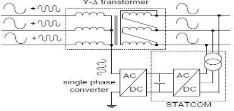
[image:3.612.174.435.175.257.2]The UPFC is the combination of a static synchronous compensator (STATCOM) and a static synchronous series compensator (SSSC), which is coupled via a common dc link, to allow bidirectional flow of active power between the series output terminals of the SSSC and the shunt output terminals of the STATCOM. The converter in series with the line provides the main function of the UPFC by injecting a four-quadrant voltage with controllable magnitude and phase.
Figure 1. Schematic representation of the UPFC
Although the UPFC and the IPFC have superior capability to control power flow, there is no commercial application currently. The main reasons are the first concern with combined FACTS is cost. Typically, a FACTS cost around 120-150 $ per KVA, compared to 15-20 $ per KVA for static capacitors. One of the reasons for the high cost is that the ratings of FACTS devices are normally in 100 MVA, with the system voltage from 100 kV to 500 kV. This requires a large number of power electronic switches in series and parallel connection. To provide voltage isolation, 3-phase high-voltage transformers are essential; furthermore, the series-connected transformers require an even higher rating to handle fault voltages and currents. Secondly, as the FACTS devices are installed at different locations for different purposes, each of them is unique. As a result, each FACTS device requires custom design and manufacturing, which leads to a long building cycle and high cost. A FACT is a complex system, and requires a large area for installation and also well-trained engineers for maintenance.
The second concern is possible failures in the combined FACTS. Two issues are considered: the reliability of the device itself and its influence on power system security. The combined FACTS is a complex system, which contains a large number of active and passive components. The large component number results that, without proper precautions, the combined FACTS have a bigger chance of failure than other PFCDs. To gain the desired reliability, complex protections (bypass circuit) and redundant backups (backup transformers and capacitor banks) are always provided for the combined FACTS device, further raising the cost, an already concerning factor. Also, a failure in the combined FACTS is more critical to the power system than in other devices. For a shunt FACTS, device failure results in a disconnection of the device from the grid which prevents it from providing reactive compensation. Because the series converter of the combined FACTS is directly inserted into transmission lines, not only the device, but also the transmission lines will be disengaged from the system during the failure.
Due to these two major drawbacks, the UPFC and IPFC are not widely applied in practice. Even when there is a large demand of power flow control within the network, the UPFC and IPFC are not currently the industry’s first choice. Normally, a phase shifting transformer, which has less control capability, is selected for economic reasons. Accordingly, a low-cost, reliable combined FACTS device has great market potential.
The flow chart for DPFC is shown in Figure below. The DPFC consists of shunt and series connected converters. The shunt converter is similar as a STATCOM, while the series converter employs the Distributed Static series compensator (DSSC) concept, which is to use multiple single-phase converters and three phase series converters. Each converter within the DPFC is independent and has its own DC capacitor to provide the required DC voltage.
[image:3.612.109.453.630.706.2]Technology (IJRASET)
III. DPFC OPERATING PRINCIPLE
Within the DPFC, the transmission line presents a common connection between the AC ports of the shunt and the series converters. Therefore, it is possible to exchange active power through the AC ports. The method is based on power theory of non-sinusoidal components. According to the Fourier analysis, non-sinusoidal voltage and current can be expressed as the sum of sinusoidal functions in different frequencies with different amplitudes. The active power resulting from this non-sinusoidal voltage and current is defined as the mean value of the product of voltage and current. The independence of the active power at different frequencies gives the possibility that a converter without a power source can generate active power at one frequency and absorb this power from other frequencies.
By applying this method to the DPFC, the shunt converter can absorb active power from the grid at the fundamental frequency and inject the power back at a harmonic frequency. This harmonic active power flows through a transmission line equipped with series converters. According to the amount of required active power at the fundamental frequency, the DPFC series converters generate a voltage at the harmonic frequency, thereby absorbing the active power from harmonic components. Neglecting losses, the active power generated at the fundamental frequency is equal to the power absorbed at the harmonic frequency.
The high-pass filter within the DPFC blocks the fundamental frequency components and allows the harmonic components to pass, thereby providing a return path for the harmonic components. The shunt and series converters, the high pass filter and the ground form a closed loop for the harmonic current.
IV. USING THIRD HARMONIC COMPONENTS
[image:4.612.130.447.344.462.2]Due to the exceptional features of 3rd harmonic frequency components in a three phase system, the 3rd harmonic is selected for active power exchange in the DPFC.
Fig. Active power exchange between DPFC converters
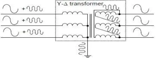
In a three-phase system, the 3rd harmonic in each phase is identical, which means they are ‘zero-sequence’ components. Because the zero-sequence harmonic can be naturally blocked by Y-∆ transformers and these are widely incorporated in power systems (as a means of changing voltage), there is no extra filter required to prevent harmonic leakage. As introduced above, a high-pass filter is required to make a closed loop for the harmonic current and the cut off frequency of this filter is approximately the fundamental frequency. Because the voltage isolation is high and the harmonic frequency is close to the cut off frequency, the filter will be costly. By using the zero sequence harmonic, the costly filter can be replaced by a cable that connects the neutral point of the Y- ∆
transformer on the right side in Figure 3.3 with the ground. Because the ∆-winding appears open-circuit to the 3rd harmonic current, all harmonic current will flow through the Y-Winding and concentrate to the grounding cable as shown in figure below. Therefore, the large high-pass filter is eliminated.
Fig Utilize grounded Y-∆ transformer to filter zero-sequence harmonic
[image:4.612.178.438.599.696.2]Technology (IJRASET)
[image:5.612.173.408.145.253.2]route the harmonic current in a meshed network. If the network requires the harmonic current to flow through a specific branch, the neutral point of the Y-∆ transformer in that branch, at the side opposite to the shunt converter, will be grounded and vice versa.
Figure below shows a simple example of routing the harmonic current by using the grounding of the Y-∆ transformer. Because the
floating neutral point is located on the transformer of the line without the series converter, it is an open-circuit for 3rd harmonic components and therefore no 3rd harmonic current will flow through this line.
Fig Route the harmonic current by using the grounding of the Y-∆ transformer
The harmonic at the frequencies like 3rd, 6th, 9th... are all zero-sequence and all can be used to exchange active power in the DPFC. However, the 3rd harmonic is selected, because it is the lowest frequency among all zero-sequence harmonics.
V. DPFC CONTROL
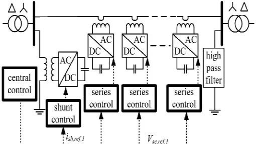
To control the multiple converters, DPFC consists of three types of controllers; they are central controller, shunt control, and series control, as shown in Figure. The shunt and series control are local controllers and are responsible for maintaining their own converters’ parameters. The central control takes account of the DPFC functions at the power-system level. The function of each controller is listed next.
A. Central Control
[image:5.612.178.433.483.627.2]The central control generates the reference signals for both the shunt and series converters of the DPFC. It is focused on the DPFC tasks at the power-system level, such as power-flow control, low-frequency power oscillation damping, and balancing of asymmetrical components. According to the system requirement, the central control gives corresponding voltage-reference signals for the series converters and reactive current signal for the shunt converter. All the reference signals generated by the central control are at the fundamental frequency. The below figure shows the control block diagram of the shunt control.
Fig .DPFC control block diagram.
B. Series Control
Technology (IJRASET)
principle of the vector control is used here for the dc-voltage control. The third-harmonic current through the line is selected as the rotation reference frame for the single-phase park transformation, because it is easy to be captured by the phase-locked loop (PLL) in the series converter. As the line current contains two frequency components, a third high-pass filter is needed to reduce the fundamental current.
The d-component of the third harmonic voltage is the parameter that is used to control the dc voltage, and its reference signal is generated by the dc-voltage control loop. To minimize the reactive power that is caused by the third harmonic, the series converter is controlled as a resistance at the third-harmonic frequency. The q component of the third-harmonic voltage is kept zero during the operation. As the series converter is single phase, there will be voltage ripple at the dc side of each converter.
[image:6.612.150.462.249.387.2]The frequency of the ripple depends on the frequency of the current that flows through the converter. As the current contains the fundamental and third harmonic frequency component, the dc-capacitor voltage will contain 100-, 200-, and 300-Hz frequency component. There are two possible ways to reduce this ripple. One is to increase the turn ratio of the single-phase transformer of the series converter to reduce the magnitude of the current that flows into the converter. The other way is to use the dc capacitor with a larger capacitance.
Fig Block diagram of the series converter control.
C. Shunt Control
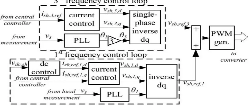
The block diagram of the shunt converter control is shown in Fig below. The objective of the shunt control is to inject a constant third harmonic current into the line to provide active power for the Series converters. The third-harmonic current is locked with the bus voltage at the fundamental frequency. A PLL is used to capture the bus-voltage frequency, and the output phase signal of the PLL is multiplied by three to create a virtual rotation reference frame for the third-harmonic component.
The shunt converter’s fundamental frequency control aims to inject a controllable reactive current to grid and to keep the capacitor dc voltage at a constant level. The control for the fundamental frequency components consists of two cascaded controllers. The current control is the inner control loop, which is to modulate the shunt current at the fundamental frequency. The q-component of the reference signal of the shunt converter is obtained from the central controller, and d component is generated by the dc control.
[image:6.612.151.555.530.702.2]Technology (IJRASET)
In the DPFC, the shunt converter should be a comparatively large three-phase converter that generates the voltage at the fundamental and 3rd harmonic frequency simultaneously. A conventional choice would be a three-leg, three-wire converter. However, the converter is an open circuit for the 3rd harmonic components and is therefore incapable of generating a 3rd harmonic component. Because of this, the shunt converter in a DPFC will require a different type of phase converter. There are several 3-phase converter topologies that can generate 3rd harmonic frequency components, such as multi-leg, multi-wire converters or three single-phase converters. These solutions normally introduce more components, thereby increasing total cost. A new topology for the DPFC shunt converter is proposed.
[image:7.612.165.405.322.436.2]The topology utilizes the existing Y-∆ transformer to inject the 3rd harmonic current into the grid. A single- phase converter is connected between the transformer’s neutral point and the ground, and injects a 3rd harmonic current into the neutral point of the transformer. This current evenly spreads into the 3-phase line through the transformer. The converter can be powered by an additional back-to-back converter connected to the low-voltage side of the transformer. For a symmetrical system, the voltage potential at the neutral point and fundamental frequency is zero. Accordingly, the single-phase converter only handles the 3rd harmonic voltages, which are much lower than the voltage at the fundamental frequency. As the single-phase converter is only used to provide active power for the series converter, the voltage and power rating are small. In addition, the single-phase converter uses the already present Y-∆ transformer as a grid connection. The single-phase converter is powered by another converter through a common DC link. In the case of the system with A STATCOM, the single-phase converter can be directly connected back-to-back to the DC side of the STATCOM, as shown in Figure below.
Fig .DPFC shunt converter configuration
VI. DPFC ADVANTAGES
The DPFC can be considered as a UPFC that employs the DFACTS concept and the concept of exchanging power through harmonic. Therefore, the DPFC inherits all the advantages of the UPFC and the D-FACTS, which are as follows:
A. High control capability
The DPFC can simultaneously control all the parameters of the power system: the line impedance, the transmission angle, and the bus voltage. The elimination of the common dc link enables separated installation of the DPFC converters. The shunt and series converters can be placed at the most effectively location. Due to the high control capability, the DPFC can also be used to improve the power quality and system stability, such as low-frequency power oscillation damping, voltage sag restoration, or balancing asymmetry.
B. High reliability
The redundancy of the series converter gives an improved reliability. In addition, the shunt and series converters are independent, and the failure at one place will not influence the other converters. When a failure occurs in the series converter, the converter will be short-circuited by bypass protection, thereby having little influence to the network. In the case of the shunt converter failure, the shunt converter will trip and the series converter will stop providing active compensation and will act as the D-FACTS controller.
C. Low cost
Technology (IJRASET)
converter is also low. Because of the large number of the series converters, they can be manufactured in series production. If the power system is already equipped with the STATCOM, the system can be updated to the DPFC with only low additional costs. However, there is a drawback to using the DPFC.
D. Extra currents
Because the exchange of power between the converters takes place through the same transmission line as the main power, extra currents at the 3rd harmonic frequency are introduced. These currents reduce the capacity of the transmission line and result in extra losses within the line and the two Y-∆ transformers. However, because this extra current is at the 3rd harmonic frequency, the increase in the RMS value of the line current is not large and through the design process can be limited to less than 5% of the nominal current.
VII.RESULT AND DISCUSSION
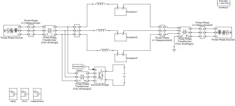
The proposed system is modelled in MATLAB/SIMULINK environment and the results have been presented. An experimental setup has been built to verify the principle and control of the DPFC. One shunt converter and six single phase series converters are built and tested in a scaled network. Two isolated buses with phase difference are connected by the line. Within the experimental setup, the shunt converter is a single-phase inverter that is connected between the neutral point of the Y–Δ transformer and the
ground. The inverter is powered by a constant dc-voltage source.
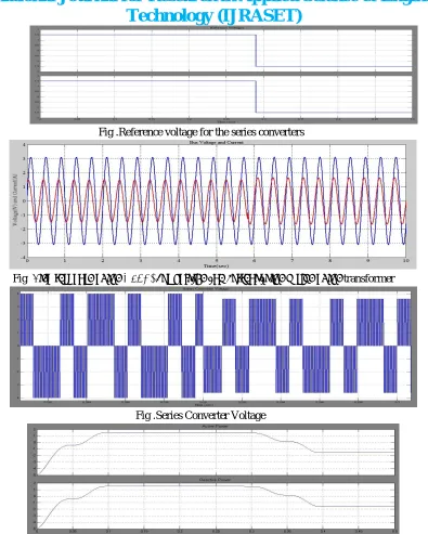
The constant third-harmonic current injected by the shunt converter evenly disperses to the three phases and is superimposed on the fundamental current. The voltage injected by the series converter also contains two frequency components. The amplitude of the pulse width modulated (PWM) waveform represents the dc-capacitor voltage, which is well maintained by the third-harmonic component in steady state. As shown, the dc voltage has a small oscillation; however, it does not influence the DPFC control. Figure demonstrates the third-harmonic filtering by the Y–Δ transformers. There is no third harmonic current or voltage leaking to the Δ side of the transformer.
The DPFC controls the power flow through transmission lines by varying the voltage injected by the series converter at the fundamental frequency. Figures below illustrate the step response of the experimental setup. A step change of the fundamental reference voltage of the series converter is made, which consists of both active and reactive variations.
As shown, the dc voltage of the series converter is stabilized before and after the step change. To verify if the series converter can inject or absorb active and reactive power from the grid at the fundamental frequency, the power is calculated from the measured voltage and current. The measured data in one phase are processed in the computer by using MATLAB. To analyse the voltage and current at the fundamental frequency, the measured data that contains harmonic distortion are filtered by a low-pass digital filter with the 50-Hz cut off frequency. Because of this filter, the calculated voltage and current at the fundamental frequency have a 1.5 cycle delay to the actual values, thereby causing a delay of the measured active and reactive power. Figure illustrated the active and reactive power injected by the series converter. A comparison is made between the measured power and the calculated power. We can see that the series converters are able to absorb and inject both active and reactive power to the grid at the fundamental frequency.
[image:8.612.102.486.528.702.2]Technology (IJRASET)
Fig .Reference voltage for the series converters
Fig .Step response of the DPFC: bus voltage and current at the Δ side of the transformer
Fig .Series Converter Voltage
[image:9.612.114.496.586.707.2]Fig .Active and Reactive power injected by the series converter at the fundamental frequency
Technology (IJRASET)
VIII. CONCLUSION
This paper has presented a new concept called DPFC. The DPFC emerges from the UPFC and inherits the control capability of the UPFC, which is the simultaneous adjustment of the line impedance, the transmission angle, and the bus voltage magnitude. The common dc link between the shunt and series converters, which is used for exchanging active power in the UPFC, is eliminated. This power is now transmitted through the transmission line at the third-harmonic frequency. The series converter of the DPFC employs the D-FACTS concept, which uses multiple small single-phase converters instead of one large-size converter. The reliability of the DPFC is greatly increased because of the redundancy of the series converters. The total cost of the DPFC is also much lower than the UPFC, because no high-voltage isolation is required at the Series-converter part and the rating of the components of is low. The DPFC concept has been verified by an experimental setup. It is proved that the shunt and series converters in the DPFC can exchange active power at the third-harmonic frequency, and the series converters are able to inject controllable active and reactive power at the fundamental frequency.
REFERENCES
[1] Y.-H. Song and A. Johns, Flexible ac Transmission Systems (FACTS) (IEE Power and Energy Series), vol. 30. London, U.K.: Institution of Electrical Engineers, 1999.
[2] N. G. Hingorani and L. Gyugyi, Understanding FACTS: Concepts and Technology of Flexible AC Transmission Systems. New York: IEEE Press, 2000. [3] L.Gyugyi, C.D. Schauder, S. L.Williams, T. R. Rietman,D. R. Torgerson, and A. Edris, “The unified power flowcontroller:Anewapproach to power
transmission control,” IEEE Trans. Power Del., vol. 10, no. 2, pp. 1085– 1097, Apr. 1995.
[4] A.-A. Edris, “Proposed terms and definitions for flexible ac transmission system (facts),” IEEE Trans. Power Del., vol. 12, no. 4, pp. 1848–1853, Oct. 1997. [5] K. K. Sen, “Sssc-static synchronous series compensator: Theory, modeling, and application,” IEEE Trans. Power Del., vol. 13, no. 1, pp. 241–246, Jan. 1998. [6] M. D. Deepak, E. B. William, S. S. Robert, K. Bill, W. G. Randal, T. B. Dale, R. I. Michael, and S. G. Ian, “A distributed static series compensator system for
realizing active power flow control on existing power lines,” IEEE Trans. Power Del., vol. 22, no. 1, pp. 642–649, Jan. 2007.