6
I
January 2018
Controlling and Analysis of Boost converter using
Sliding mode controller at variable Conditions
Sandeep Tyagi1, Garima Verma2
1,2
Department of Electrical & Electronics Engineering Rajasthan Institute of Engineering & Technology, Bhakrota, Jaipur (India)
Abstract: As the requirement of power increases, it is required to increase the generation on demand. Now a days, solar PV and wind are increasingly used for generation. The power collected from these energy source need to be converted using DC-Dc or AC- Dc converters. The main converter used is Boost converter for step up this voltage. These sources are variable by nature, so problem arises is to maintain constant required output in all conditions.
Boost converter converts the input voltage into higher value of voltage but as per the input is received. This issue can be resolved by using sliding mode control of the converter. There are many theories to implement this technology with converter but the problem arises when the inductance and capacitance changes as load varies. The proposed work is to resolve this problem by using sliding mode controller with modified values of parameters and beta factor for precise values using feedback, close loop system. The input source is taken as DC source voltage at variable conditions. The modelling done in MATLAB/Simulink software.
Index Terms: Solar PV, Wind, Boost Converter, slide mode controller
I.BOOSTCONVERTER
For example, applications for boost converter operations are DC Motor's rebounding breaking circuit and regulated DC power supply. In this type of converter, the output voltage is always greater than the input voltage. Therefore, the speed-up converter can be applied to the MPPT system where the output voltage should exceed the input voltage. Such as in the systems connected to the grid, where the boost converter holds a high output voltage, even if the PV array voltage falls at lower prices. Circuit topology of
step-up converter as shown in Fig. 1 [1-3]
Fig.1. Equivalent Circuit of Boost Converter
= 1− (1)
=
∆ (2)
=
Δ (3)
ton toff
Ts
IL
iL
0
(Vd-Vo) (-Vo)
VL
[image:3.612.201.446.78.197.2]0
Fig.2. Triggering Pattern for Boost Converter Pulses
[image:3.612.70.544.270.313.2]Designing Boost Converter made in MATLAB. This includes the inductor (L), input DC voltage, MOSFET, diode, capacitor and load resistance. Table 1 shows the basic parameters taken for analysis and designing.
Table.1. Parameters for Boost converters
Input Voltage (V) L-R (mH-Ohm) Load R(Ohm) R-C(mOhm-µF)
200 300 – 0.14 240 69-2300
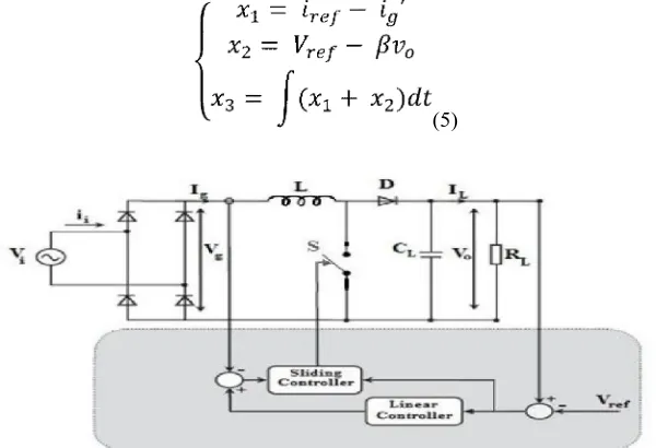
II.SLIDEMODECONTROLLINGOFBOOSTCONVERTER
Technically, this controller has a time-separate state-response imbalance control law, in which due to the current situation of state variables in state, switching from one continuous structure to another is possible with high frequency. Its purpose is to control the system's mobility to follow the desired and predetermined.
Sliding mode has been applied to current controller technology to boost converter. Fig 3 represents the basic circuit diagram of the boost converter controlled by the sliding mode controller. This control plan for boost converter starts with selecting the sliding
surface. At present, the continuous growth results in direct surface almost zero. By the voltage error, the external
voltage loop reference produces the current. The existence of stability criteria and sliding mode can be achieved by controlling the output voltage of the AC-DC converter. The inductor is currently controlled by the internal current loop through the sliding mode technology. Current SMC is used for regulation, due to which voltage loop high frequency switching and reference is currently highly sensitive to uncertainties. Therefore, the sliding surface is for better performance; [4-8]
(4)
where , and are the control parameters, generally stated as sliding coefficients and 1 , 2 and 3 are called as the desired
state feedback variables which are to be controlled.
(5)
[image:3.612.157.457.501.706.2]SM For the operation, there are three necessary conditions, the condition of the kill, survival and stability. The result of the control function to kill the situation;
(6) Considering the continuous conduction of boost converter and by time differentiation, from equation 6, the system dynamic model is;
(7)
Where ̅= 1 – u, is considered as inverse logic of u.
By solving the equation the equivalent control signal would be;
(8) Where, 1 and 2 are the fixed gain parameters.
(9)
And it can be represented in terms of the controlled state variable like as;
(10)
From the sliding surface 10, the controller is driven and is executed through a PWM, comparing (duty ratio of the PWM
controller). The control law equation is described as in fig.3, involving;
(11)
The factor = (0,1), is introduced purposefully to down scale the equation to a practical level of magnitude. To make the duty
ratio of the output of the controller always below 1, a multiplier is incorporated for the multiplication of and . By a logic
AND operator the impulse generator creates . Based on equation 11, the controller is designed with assuming = .
The control law and the sliding gain coefficients should be designed in such to fulfill the stability condition. This is to make sure that the trajectory is directed by the desired sliding manifold and always towards a stable equilibrium point.
III.SIMULATIONANDRESULTS
Fig.4. MATLAB model for Boost Converter
Mode of operation of Boost converter slide mode controller
In the proposed work, the sliding mode controller works for different conditions of Boost Converter as listed below: Boosting mode 200 to 350 V
Booting mode 240V to 400 V
A. Boost Mode Of Slide Mode Controller For 200 To 350 V
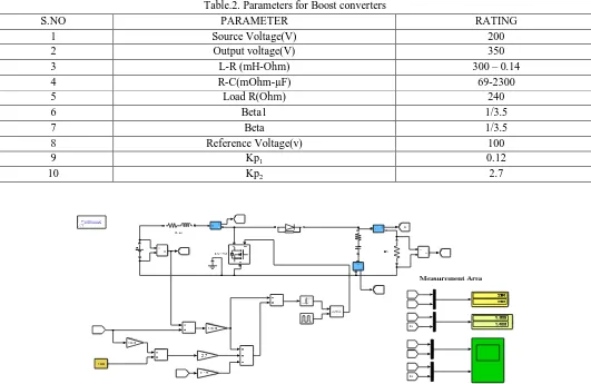
[image:5.612.41.572.366.711.2]In this mode of operation, slide mode controller controls the output to 350 V as the input DC power is 200 V. As shown in fig.5, MATAB model designed and the parameter for the same are:
Table.2. Parameters for Boost converters
S.NO PARAMETER RATING
1 Source Voltage(V) 200
2 Output voltage(V) 350
3 L-R (mH-Ohm) 300 – 0.14
4 R-C(mOhm-µF) 69-2300
5 Load R(Ohm) 240
6 Beta1 1/3.5
7 Beta 1/3.5
8 Reference Voltage(v) 100
9 Kp1 0.12
10 Kp2 2.7
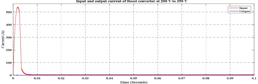
Fig.6. Input and output current of Boost converter at 200 V to 350 V
Fig.6 shows the current input and output waveforms for sliding mode controller of Boost converter when input DC is 200 V and required output is 350 V. as there is requirement of voltage step up and to maintain constant output, therefore the output current received is decreased. The input current is 1.326 A and output received is 1.458 A.
Fig.7 Input and output voltage of Boost converter at 200 V to 350 V
Fig 7 shows the voltage input and output waveforms for sliding mode controller of Boost converter when input DC is 200 V and required output is 350 V. input voltage is 200 V and output gain is 350V. the output is constant to 350 V approx..
B. Boost Mode Of Slide Mode Controller For 240 To 400 V
[image:6.612.35.580.571.727.2]In this mode of operation, slide mode controller controls the output to 400 V as the input DC power is 240 V. As shown in fig.8, MATAB model designed and the parameter for the same are:
Table.4.2. Parameters for Boost converters
S.NO PARAMETER RATING
1 Source Voltage(V) 240
2 Output voltage(V) 400
3 L-R (mH-Ohm) 300 – 0.14
4 R-C(mOhm-µF) 69-2300
5 Load R(Ohm) 240
6 Beta1 1/4
7 Beta 1/4
8 Reference Voltage(v) 100
9 Kp1 0.12
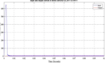
Fig. 8. Slide mode control of Boost Converter at 240 V to 400 V
[image:7.612.95.519.426.680.2]Fig.9 shows the current input and output waveforms for sliding mode controller of Boost converter when input DC is 240 V and required output is 400 V. as there is requirement of voltage step up and to maintain constant output , therefore the output current received is decreased. The input current is 2.403 A and output received is 1.6667 A.
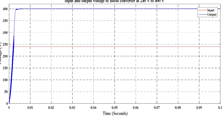
Fig.10. Input and output voltage of Boost converter at 240 V to 400 V
Fig 10 shows the voltage input and output waveforms for sliding mode controller of Boost converter when input DC is 240 V and required output is 400 V. input voltage is 240 V and output gain is 400.1 V.
III. CONCLUSION
The proposed system is slide mode controller for Boost converter using variable parameter and beta gain function. The analysis is performed on two different conditions of input 200 V and 240 V at required output of 350V and 400 V. a closed loop system is designed in MATLAB and output voltage and current are measured. The output waveforms describes that the system works more efficient at higher voltage rating and as a property of converter current output decreases. In both the conditions the output is maintained constant and as per feedback gain (beta) it gives controlled gate signals to MOSFET.
REFERENCES
[1.] S. Ahmadzadeh, G. Arab Markadeh and F. Blaabjerg, "Voltage regulation of the Y-source boost DC–DC converter considering effects of leakage inductances based on cascaded sliding-mode control," in IET Power Electronics, vol. 10, no. 11, pp. 1333-1343, 9 9 2017.
[2.] C. Asma, Z. Abdelaziz and Z. Nadia, "Dual loop control of DC-DC boost converter based cascade sliding mode control," 2017 International Conference on Green Energy Conversion Systems (GECS), Hammamet, 2017, pp. 1-6.
[3.] B. A. Martínez-Treviño, A. E. Aroudi and L. Martínez-Salamero, "Sliding-mode approach for start-up control and voltage regulation of a boost converter driving a constant power load," 2017 IEEE International Symposium on Circuits and Systems (ISCAS), Baltimore, MD, 2017, pp. 1-4.
[4.] A. Kihel, F. Krim and A. Laib, "MPPT voltage oriented loop based on integral sliding mode control applied to the boost converter," 2017 6th International Conference on Systems and Control (ICSC), Batna, 2017, pp. 205-209.
[5.] P. R. Mohanty and A. K. Panda, "Fixed-Frequency Sliding-Mode Control Scheme Based on Current Control Manifold for Improved Dynamic Performance of Boost PFC Converter," in IEEE Journal of Emerging and Selected Topics in Power Electronics, vol. 5, no. 1, pp. 576-586, March 2017.
[6.] A. Ghasemian and A. Taheri, "Constrained Near Time-Optimal Sliding Mode Control of Boost Converters Based on Switched Affine Model Analysis," in IEEE Transactions on Industrial Electronics, vol. PP, no. 99, pp. 1-1.
[7.] S. K. Pandey, S. L. Patil and S. B. Phadke, "Comment on “PWM-Based Adaptive Sliding-Mode Control for Boost DC-DC Converters”," in IEEE Transactions on Industrial Electronics, vol. PP, no. 99, pp. 1-1.
[8.] Yanmin Wang, Yuqing Cao, Tienan Liu, Hongwei Xia and Bao Ding, "Terminal sliding mode control of boost converter using an energy storage function model," IECON 2016 - 42nd Annual Conference of the IEEE Industrial Electronics Society, Florence, 2016, pp. 354-358.
[10.] S. Barhoumi, A. Sahbani and K. Ben Saad, "Sliding Mode Control for a Boost converter with Constant Power Load," 2016 4th International Conference on Control Engineering & Information Technology (CEIT), Hammamet, 2016, pp. 1-5.
[11.] İ. Yazici and E. K. Yaylaci, "Fast and robust voltage control of DC–DC boost converter by using fast terminal sliding mode controller," in IET Power Electronics, vol. 9, no. 1, pp. 120-125, 1 20 2016.
[12.] M. B. Debbat, H. A. Bouziane and R. B. Bouiadjra, "Sliding mode control of two-level Boost DC-DC converter," 2015 4th International Conference on Electrical Engineering (ICEE), Boumerdes, 2015, pp. 1-5.
[13.] A. Leon-Masich, H. Valderrama-Blavi, J. M. Bosque-Moncusí, J. Maixé-Altés and L. Martínez-Salamero, "Sliding-Mode-Control-Based Boost Converter for High-Voltage–Low-Power Applications," in IEEE Transactions on Industrial Electronics, vol. 62, no. 1, pp. 229-237, Jan. 2015.
[14.] O. Lopez-Santos, L. Martinez-Salamero, G. Garcia, H. Valderrama-Blavi and T. Sierra-Polanco, "Robust Sliding-Mode Control Design for a Voltage Regulated Quadratic Boost Converter," in IEEE Transactions on Power Electronics, vol. 30, no. 4, pp. 2313-2327, April 2015.