Studying an Inductive Iris by an Optimized 1D-WCIP
Method based on a Phase Jump Fast Mode Transform
(PJFMT)
Sameh Bennour
University of Tunis ELmanar Sciences Faculty of Tunis
Tunisia
Ecole Superieure d’aéronautique et des
Technologies
Hafedh Hrizi
University of Tunis ELmanar Sciences Faculty of Tunis
Tunisia
Noureddine Sboui
University of Tunis ELmanar Sciences Faculty of Tunis
Tunisia
ABSTRACT
The wave iterative method is an efficient tool used to study electronic circuits at high frequencies. The major problem with this method is that the required calculation time increases with the complexity of the circuit. In this article, we propose to accelerate the iterative process by using a Phase Jump Fast Mode Transform (PJFMT) based on phase jump principle in order to improve the convergence speed of this method. Preliminary numerical results are presented and show good agreement when compared to HFSS simulation.
Keywords
Inductive Iris; Iterative Method; 1D-WCIP ; PJFMT;
1.
INTRODUCTION
The wave iterative method (WCIP) (Wave Concept Iterative Process) is an integral method based on wave concept for solving problems of electromagnetic diffraction and analysis of planar circuits [1-8]. It is based on the manipulation of incident and reflected waves instead of electromagnetic field [1-4]. It is mainly based on two equations, one in the spatial domain and the other in the spectral domain. It has very attractive benefits for microwave circuits‟ designers. Among These benefits, its facility of implementation and execution speed, mainly due to the absence of test functions (replaced by a pixel description of the interface containing the circuit) and the use of the FMT (Fast Modal Transform) [9] ensuring the transition between spatial and spectral domains.
In fact, in recent years, the FMT-WCIP method has been applied in a wide variety of microwave structures. This method uses a Fast Fourier Transform FFT. The use of the FFT algorithm requires considering the circuit plane as an image divided into a small cells. By using the FFT algorithm, a high computing speed can be obtained. But, in the case of complex circuits requiring a fine mesh, the time calculation increases [10], because the numerical complexity is related to the number of cells describing the circuit. In previous works, several improvements have been presented as the technique of adaptive filtering [11] and contour detection [12]. In this article, we propose a new algorithm of the 1D-WCIP based on a modified 1D-FMT. This modification consists on a phase jump when performing the FFT transform „Phase Jump Fast Mode Transform PJFMT‟. In fact, the new PJFMT takes as input data only the useful information from the cells describing the structure. This useful information corresponds to high values of the electromagnetic fields, usually located in the areas of the structure discontinuity between the metal and the dielectric. In fact, the rapidity of the 1D-FMT can be ameliorated by removingoperations on the input values that
are not needed. In our case, it is known in advance that parts of the input data of the 1D-FMT are not useful, so we focus only on important information while the rest will be ignored. In fact, the application of this method reduces the number of operations by the rejection of unnecessary operations and then we can accelerate the iterative process. For a simplicity reason, this new approach is first developed and tested for one-dimensional 1D TE and TM problems to be extended in future work for the 2D case. In fact, we will manipulate a sequence of vectors describing the studied structure instead of matrices.
In section 2, we present the theoretical formulation of the problem, for the 1D TE field.
In Section 3, the numerical results of convergence and computation time are given as well as a comparison of our results with HFSS simulation. Section 4 presents comparison of the classic method with the new method. Finally, section 5 deals with conclusions and perspectives.
2.
THEORETICAL STUDY
2.1
1D-WCIP
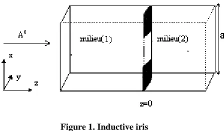
[image:1.595.324.548.514.645.2]The WCIP method is described on a 1D circuit formed by an inductive iris placed on a waveguide, shown in Figure 1.
Figure 1. Inductive iris
In this case, the discontinuity is uniform along y-axis, and since the electromagnetic field is incident in the dominant TE10 mode, only higher-order modes TEm0 are generated [13].
Figure 2.Exemple of Discretization of the iris surface on 16 cells
If we consider only the TE mode, A0 is along y-axis, which makes that the generated waves are also along y-axis. The process of WCIP is based on the manipulation of incident Ai and reflected Bi waves at the meshed surface (where „i‟ is the domain number 1 or 2 in Figure 1). These waves are defined by equations (1) and (2):
(1)
(2)
The current density is defined by:
J
iH
in
i
,n
i is orientedto the areai
1
,
2
.i
H
andE
i
indicate respectively the tangential magnetic and
electric field at the surface.
oi
Z
is the impedance of the medium „i‟.The iterative process establishes a recurrent relation between the incident waves and the reflected waves in the two different areas as indicated by the following equations [14].
0
A
B
A
(3)A
B
(4)Where the source is specified through a known vector A0
added in equation (3).
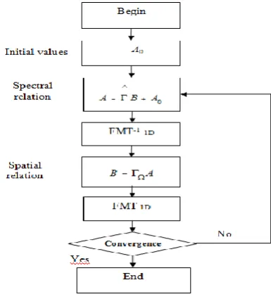
The transition from the spatial domain (pixel representation) to the spectral domain (modal representation) is insured by the Fast Mode Transformation (1D-FMT) and the reverse Transformation (FMT-11D) which will be described in the next
paragraph. Figure 3 summarizes the iterative process.
Figure 3. Classic iterative process for spectral the excitation case
2.2
FMT 1D
The 1D-FMT and the 1D-FMT-1 are respectively based on a Fast Fourier transform FFT and an Inverse Fast Fourier Transform FFT-1.
We consider a complex field E(x,y) defined in the spatial domain as:
)
y
,
x
(
e
)
y
,
x
(
e
y
,
x
E
y x (5)The decomposition of E(x,y) along the modal base is given by:
mn TM mn TM TE mn TEf
e
f
e
E
(6) (6)In the studied case, we consider only TEm0 modes, so that:
0 0 m TE m TEm
e
f
E
(7) With:)
,
(
)
,
(
)
,
(
)
,
(
0 0 0y
x
e
f
y
x
e
f
y
x
e
y
x
e
f
e
y TE y m x TE x m y x TE m TE
(8)The modal functions are given by:
[image:2.595.88.278.83.288.2]Whith N1 is a constant which depend on the mode nature.
ab
a
m
b
n
a
m
N
2
mn)
(
)
(
2 21
(10)1
mn
ifm
.
n
0
In this case, we have
m
.
n
0
, then N1 becameab
N
1
2
Returning to equation (8), we will obtain:
)
,
(
sin
)
,
(
0
)
,
(
)
,
(
1 0 0y
x
e
a
x
m
N
y
x
e
y
x
e
f
y
x
e
f
e
y x y TE y m x TE x m TE
(11)Since we have invariance according to y-axis, then
TE
e
canbe calculated as:
)
(
sin
1
e
x
a
x
m
N
e
y TE
(12)Discretizing the variable x, we obtain
a
x
M
i
The scalar product becomes:
M i y y y mM
i
m
i
e
x
e
f
0(
)
(
)
sin
(13)
Thus, we can define the fast modal transformation 1D-FMT noted Em of Ey as equation (14):
E
e
i
a
FFT
E
m
y.
ix.
2
.
.
2
(14)
With analogy to the 1D-FMT, the FMT-11D is given by:
a
i
e
E
IFFT
E
x i m y2
.
.
2
)
.
(
(15)Our goal is to modify the blocs of the FMT and the 1D-FMT-1 in the classic iterative process and to propose a new algorithm in which we replace the basic FFT and FFT-1 by modified ones taking as input only the relevant data based on a phase jump, in order to perform the calculation without loss of information. The formulation of the new 1D-FMT is developed in the following paragraph.
2.3
New 1D-FMT based on Phase Jump
Our goal is to propose a modified 1D-FMT called PJFMT able to perform the calculation only on the important points from the original vector and to neglect the others without information loss. In order to reduce the computation time, we apply the fast modal transform to the new vector and we should have the same phase and the same amplitude when performing the FFT as if we work with original vectors, in order to converge to the same final result. This will be done
using phase jump when performing the FFT. The relation between the 1D-FMT and the Discret Fourier Transform DFT was given in the previous paragraph.
The discret fourier transform DFT is given by :
mk M M
k k
m
x
w
X
1 1 (16)With:
w
M
e
2i/MIf we consider a basic vector V of lengh M containing all the points (xk) with 0≤k≤M, from which we extract a reduced set
of points (xk‟) forming a new vector V‟ of a lengh M‟, with
0≤k‟≤M‟. We define a new indice s, with 0≤s≤M‟ verifying xk‟=xs.
We aim to have this final result:
' ' ' k mk M km
x
w
X
(17)If we apply the DFT1D to the new vector V‟ we will have the
following result:
' 10 ' M s ms M s
m
x
w
X
(18)With:
w
M'
e
2i/M'We should have:
' k
s
x
x
(19)But the equality of these two terms doesn‟t mean the equality of their indices, so we must have:
' ' mk M ms M
w
w
(20)If we consider that M=C*M‟, we should have, with C=constant
C
k
s
'
(21)In fact, if we respect this condition, we will reduce the number of performed operation, and hence we gain in term computation time, without loss of information, since the calculation is done using a phase jump principle in order to have the same phase and amplitude when working with few numbers of points.
In conclusion, the proposed 1D-FMT treats new vectors without loss of information.
Vectors „x‟ and „X‟ in the theoretical study designate thereafter the incident and reflected waves A and B in both domains.
2.4
New algorithm
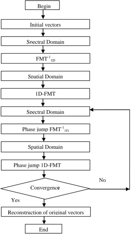
Our goal is to reduce the computation time by the new algorithm. We use the phase jump FMT technique that works on useful points; these ones are located around the discontinuity dielectric - metal of the studied structure. Useful information is extracted from the original vector of length M, describing the structure, and then we construct a new vector of length M‟. We do not consider negligible values so that much of points are rejected. In the proposed new algorithm given in Figure 4, the calculation is performed by the phase jump 1D-FMT in order to have the same phase and amplitude when performing the FFT.
The new whole process starts with the classic 1D-FMT which performs a few number of iterations (n) applied to the initial vectors having basic lengths M, until the stability of the process. Then we apply the new algorithm of the 1D-WCIP based on phase jump 1D-FMT to continue the remaining iterations and to achieve the convergence after "N" iterations. At the end, we reconstruct the original vectors. The new algorithm operates with a new 1D-FMT which uses a reduced set of points describing the circuit as input, based on a phase jump when performing the FFT, in order to reduce the computation time and to get a good result.
Figure 4. New algorithm
3.
SIMULATION RESULTS
[image:4.595.58.274.362.738.2]Along all that it follows, the studied structure is a vertical iris described by a vector of 32 points, since the electromagnetic field is invariant along y axis.
Figure 5. The inductive Iris
The set of geometric features are: a = 6.4 cm, b = 3.2mm. The working frequency is f =3.24 GHz.
3.1
Convergence
In figures 6 and 7, we show the variation of S11 and S21 coefficients in function of the number of iterations using two methods: the classic 1D-WCIP with basic 1D-FMT and the new method with phase jump 1D-FMT to prove that our approach gives good results. The classic method needs 300 iterations to achieve the convergence. Those iterations are calculated by a classic iterative process based on a basic 1D-FMT. Since this number is quite high, it requires an important calculation time. So, this method takes a long time to achieve the optimal result. In fact, to reduce the calculation time required to have a good result, we propose to use a new iterative process in which the basic 1D-WCIP method is used to calculate a few number of iteration “n” set to 20 to reach the stability, while the remaining important number of iterations “N” is calculated by the new approach based on a phase jump 1D-FMT, which does not take much time to achieve convergence. This new process uses two algorithms: one uses the classic 1D-FMT in which is added a second one in which we use the new 1D-FMT. We show that the final result of the hole system converge also to the optimal values of S11 and S21 when compared to the classic 1D-WCIP .
Figure 6. Variation of S21 by both methods
0.6 0.65 0.7 0.75 0.8 0.85 0.9 0.95 1 1.05 1.1
50 100 150 200 250 300
S
21
dB
FMT PJFMT
Begin
FMT-11D
Spectral Domain
Spatial Domain Initial vectors
Phase jump FMT-11D
Phase jump 1D-FMT 1D-FMT
Spectral Domain
Spatial Domain
Convergence
Reconstruction of original vectors Yes
No
[image:4.595.327.557.572.742.2]Figure 7. Variation of S11 by both methods
3.2
Variation of S11 and S21 in function of
frequency
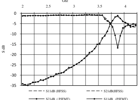
In figure 8 we show the variation of the coefficients S11 and S21 in function of the frequency. These coefficients are calculated by our new method. These results are compared with those calculated by the basic 1D-WCIP method in order to make sure that our results are optimal ones. The number of iterations calculated by both methods is “N=300” iterations. In the new WCIP 1D method, n is set to 20 basic iterations. Good results are obtained in comparison with the classic method. In fact, in our new method, the basic algorithm with basic FMT 1D which have a large input data is used to calculate only 20 iterations and the following iterations are calculated by the new iterative process based on a phase jump 1D-FMT which works with fewer numbers of input points selected from the original vectors, until the completion of the whole 300 iterations. That is why the new approach takes less calculation time, unlike the classic method WCIP 1D, where all iterations (300) are calculated on vectors of high sizes containing all the points (useful and not useful information). Thus, our main goal which is the reduction of computation time needed to reach the optimal results is performed. Good and optimal results are obtained by the new method. These results were compared to HFSS simulation.
Figure 8. Variation of S21 and S11 by both methods
[image:5.595.56.284.76.237.2]3.3
Inductive Obstacle Analysis
[image:5.595.325.546.77.239.2]Figure 9 presents the input reactance of the inductive iris in a frequency range from 2 to 6 GHz, fordifferent values of the ratioof obstacle and waveguide width (d/a). We show that, when the obstacle width increases, the reactance will also increase, what isconsistent with the properties of the inductor.
Figure 9. Variation of the reactance for different d/a values
3.4
Gain in time calculation
In this paragraph, the two methods: the classic method 1D-WCIP with basic 1D-FMT and the new method based on a phase jump 1D-FMT are used to calculate the same number of iterations N=300 in order to make a comparison between them in term of computation time. In the table below, we observe a significant gain in the time of convergence when calculating the values of the scattering parameters S11 and S21 after N iterations by both methods.
[image:5.595.54.282.518.681.2]This gain of time is achieved by the new method because we added a modified 1D-FMT based on phase jump which performs the calculation on a fewer numbers of input points doing a phase jump when calculating the FFT to converge to the same result in less time. In addition, we note that our algorithm reaches the convergence faster than the classic method of 1D-WCIP.
Table 1. Gain in time calculation for the initial iteration
number n=20
n 1D-FMT for
N=300
1D-PJFMTfor N=300
GAIN
« Time in second »
« Time in second»
20 1.4 0.3 78%
4.
COMPARISON AND ANALYSIS
In this section, we compare the results given by the two methods, the classic method 1D WCIP with basic 1D-FMT and the new method based on a phase jump 1D-FMT in order to prove that the new method provides better results.
In fact, if we analyse the results presented in the last paragraphs, we notice that we enhance the convergence of the classic wave iterative method because the new proposed algorithm based on phase jump gives good results and it doesn‟t take much time to converge to the optimal result. So if we consider the comparison table presented, an important gain in convergence time when calculating S11 and S21 values by the new method “phase jump WCIP” compared to the classical WCIP method, is noticed. This gain of time is provided by the new method for the same number of iteration N=300 and the same iris structure discretized in 32x32 pixels.
0 0.1 0.2 0.3 0.4 0.5 0.6
50 100 150 200 250 300
S
11
dB
FMT PJFMT
-35 -30 -25 -20 -15 -10 -5 0
2 2.5 3 3.5 4
S
d
B
Ghz
S11dB (HFSS) S21dB(HFSS) S21dB ( PJFMT) S11dB (PJFMT)
0 0.5 1 1.5 2
2 2.4 2.8 3.2 3.6 4 4.4 4.8 5.2 5.6 6
R
ea
ct
an
ce
o
f
in
duc
ti
v
e
ir
is
(
K
o
h
m
)
Ghz
We can then conclude that the new method provides the same results as the classical WCIP method, but it is very rapid in terms of calculation time. We can explain this by the fact that the WCIP method uses only the classic iterative algorithm to calculate all the 300 iterations which takes much time, while the proposed method uses the classical iterative algorithm to calculate only a few number of 20 iterations when the remaining iterations until 300 are calculated by phase jump algorithm which is more rapid and faster than the classical one. That‟s why we have this large gain in computing time which is our principal goal and then we have a fast convergence compared to the classic iterative algorithm.
5.
CONCLUSION
In this work, we have proposed a new method to improve the speed of the iterative method 1D-WCIP. This method is based on a phase jump 1D-FMT, which perform the calculation only on the useful points of the input vector describing the structure. This approach has been tested firstly, on a simple one-dimensional electromagnetic structure which consists on an inductive iris. The future scope of this idea consists on adapting this new method to more complex circuits in two dimensions 2D described by large matrices, using a correct modification of the FFT2 based on the phase jump principle, and then including this approach in the WCIP2D process.
6.
REFERENCES
[1] N. Sboui, A. Gharsallah, H. Baudrand, and A. Gharbi, „„Global Modeling of Microwave Active Circuits by an Efficient Iterative Procedure,” IEEE Proc-Microw. Antenna Propag., vol. 148, no. 3, June 2001.
[2] N. Sboui, A. Gharsallah, H. Baudrand, and A. Gharbi, „„Design and Modeling of RF MEMS Switch by Reducing the Number of Interfaces,‟‟ Microw. and Opt. Technol. Lett vol. 49, no. 5, pp. 1166-1170, May 2007.
[3] N. Sboui, L. Latrach, A. Gharsallah, H. Baudrand, and A. Gharbi, “A 2D Design and Modeling of Micro strip Structures on Inhomogeneous Substrate,” Int. Journal of RF and Microwave Computer –Aided Engineering, vol. 19, no. 3, pp. 346-353, May 2009.
[4] N. Sboui, A. Gharsallah, H. Baudrand, and A. Gharbi, “Global Modeling of Periodic Coplanar Waveguide Structure for Filter Applications Using an Efficient Iterative Procedure,” Microwave and Opt. Technol. Lett, vol. 43, no. 2, pp. 157-160, 2004.
[5] N. Sboui, A. Gharsallah, A. Gharbi, and H. Baudrand, “Analysis of Double Loop Meander Line by Using Iterative Process,” Microw. Optical Technical Letters, vol. 26, pp. 396-399, June 2000.
[6] L. Latrach, N. Sboui, A. Gharsallah, H. Baudrand, and A. Gharbi, “A Design and Modelling of Microwave Active Screen Using a Combination of the Rectangular and Periodic Waveguides Modes,” Journal of Electromagnetic Waves and Applications, vol. 23, no. 11-12, 2009.
[7] L. Latrach, N. Sboui, A. Gharsallah, H. Baudrand, and A. Gharbi, “Analysis and Design of Planar Multilayered FSS with Arbitrary Incidence,” Applied Computational Electromagnetic Society Journal, vol. 23, no. 2, pp. 149-154, June 2008.
[8] A.Gharsallah, A.Gharbi, L.Desclos and H.Baudrand "Analysis of interdigital and quasi-lumped miniaturized filters using iterative method". International Journal of Numerical Modelling: Electronic Network. Devices and Fields Int. J. Numer. Model.2002, 15:169-179
[9] Zied Harouni1,*, Lassaad Latrach1 , Lotfi Osman1 , Ali Gharsallah1 , Henri Baudrand2Global Analysis of Rectifying Antenna with GaN Schottky Barrier Diode using WCIP Method for Wireless Power Transmission
[10]Gharbi Ramzi1 , Zairi Hassen1 , Trabelsi Hichem1 , Baudrand Henri2, Analysis of Complex Electromagnetic Structures by Hybrid FDTD/WCIP Method, Journal of Electromagnetic Analysis and Applications, 2012, 4, 497-503
[11]H. Hrizi, L. Latrach, N. Sboui, A. Gharsallah, A. Gharbi, and H. Baudrand, “ Improving the Convergence of the Wave Iterative Method by Filtering Techniques,” Journal of Applied Computational Electromagnetics Society, vol. 26, no. 10, 2011
[12]H. Hrizi, and N. Sboui, “Reducing the Numerical Calculation in the Wave Iterative Method by Image Processing Techniques,” Journal of Applied Computational Electromagnetics Society, vol. 27, no.6, 2012.
[13]Gyu Yeong Choa*, Hyeon Dong Choa & Wee Sang Parka Investigation of higher-order modes in finite-width parallel-plate waveguide, Journal of Electromagnetic Waves and Applications Volume 27, Issue 12, 2013