Tool planning in batch manufacturing.
PATANGE, Vinay B.Available from Sheffield Hallam University Research Archive (SHURA) at: http://shura.shu.ac.uk/20211/
This document is the author deposited version. You are advised to consult the publisher's version if you wish to cite from it.
Published version
PATANGE, Vinay B. (1993). Tool planning in batch manufacturing. Doctoral, Sheffield Hallam University (United Kingdom)..
Copyright and re-use policy
See http://shura.shu.ac.uk/information.html
Sheffield Hallam University Research Archive
Sheffield Hallam University
REFERENCE ONLY
sail
22>\~l
ProQuest Number: 10700856
All rights reserved
INFORMATION TO ALL USERS
The quality of this reproduction is dependent upon the quality of the copy submitted.
In the unlikely event that the author did not send a com plete manuscript and there are missing pages, these will be noted. Also, if material had to be removed,
a note will indicate the deletion.
uest
ProQuest 10700856
Published by ProQuest LLC(2017). Copyright of the Dissertation is held by the Author.
All rights reserved.
This work is protected against unauthorized copying under Title 17, United States C ode Microform Edition © ProQuest LLC.
ProQuest LLC.
789 East Eisenhower Parkway P.O. Box 1346
TOOL PLANNING IN BATCH
MANUFACTURING
Vinay Baburao Patange
A thesis submitted in partial fulfilment of the
requirements of
Sheffield Hallam University
for the Degree of
ABSTRACT
TOOL PLANNING IN BATCH MANUFACTURING
by Vinay Patange
This work concentrates on the newly growing science of managing tooling in conventional manufacturing. Various Tool Management (TM) problems and the approaches suggested by other researchers to solve these problems are given. This work establishes the basic structure of TM applicable to a conventional manufacturing. Systems Analysis and Design Methodology (SSADM) is used to study the information needs of a typical TM System.
It is stressed that the majority of TM problems are due to unavailability of correct information. Success of any TM system depends upon having a good Information System. This work focuses on the tool planning problems in batch manufacturing. The causes of tool planning problems are discussed. The research aims to develop a generic methodology for planning the tools. The information required to carry out the primary functions of any Tool Planning System (TPS) is identified. The fundamental characteristics of different tools from the planning perspective are studied in detail. The principles on which a generic TPS could be designed are laid out. The mechanism of a Tool Planning System is developed.
The TPS model is implemented using Foxpro, a DBMS. This model illustrates the concepts of planning tools with the information that can be obtained from other functions of manufacturing. The effectiveness of the developed TPS model is investigated using simulation. The impact of the TPS on the performance of a typical Job Shop Environment is studied and compared with other models with traditional stock control approaches.
PREFACE
This thesis is submitted to the School of Engineering of Sheffield Hallam University for
the degree of Doctor of Philosophy. This research was carried out in the Division of
Design and Manufacture of School of Engineering.
I would like to express my deepest gratitude and appreciation to my supervisor
Dr.D.T.S. Perera for his guidance and encouragement throughout the course of this
work. I would like to thank my research colleagues, the technical, administrative and
lecturing staff within the School of Engineering for their help and support.
The results obtained and the theories developed during the course of this research are
to the best of my knowledge original, except where the reference is made to the work
CONTENTS
Page
ABSTRACT i
PREFACE ii
1 GENERAL OVERVIEW 1
2 LITERATURE SURVEY 4
2.1 Introduction 4
2.2 TM Research on FMS 6
2.3 Use of FMS Tool Planning Techniques for Conventional
Manufacturing 9
2.4 TM Research for Conventional Manufacturing 10
2.5 Developments in TM Software 15
2.6 Problem Definition 17
3 FUNDAMENTALS OF TOOL PLANNING 18
3.1 Introduction 18
3.2 Selecting a suitable technique for analysing the TM System 19
3.3 Functional Analysis 20
3.4 Interaction of TM with other Functions of Manufacturing 23 3.5 Functions of TM in Conventional Manufacturing 26
3.6 Tool Classification 31
3.7 Fundamentals of Tool Planning 34
4 TOOL PLANNING METHODOLOGY 51
4.1 Introduction 51
4.2 Tool Planning Methodology 51
4.2.1 Deriving the Tool Requirements in Time Buckets 52 4.2.2 Time Phasing of Tool Planning Activities 59
4.2.3 Allocation of Tools 64
Contents
DEVELOPMENT OF TOOL PLANNING SYSTEM
Page
71
5.1 Introduction 71
5.2 Selection of a Suitable Database Package 71
5.3 Database Specification for Tool Planning System 73 5.4 Tool Planning Model - The Programmimg Logic 87
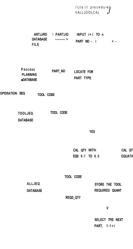
5.4.1 Part Tool Calculation Procedure 89
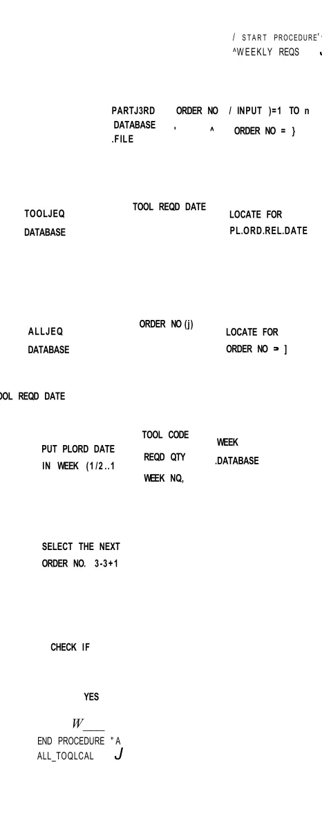
5.4.2 Weekly Requirements Procedure 91
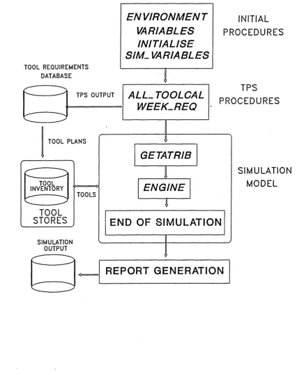
SIMULATION MODELLING OF TOOL PLANNING SYSTEM 96
6.1 Introduction 96
6.2 Selecting a Simulation System 97
6.3 Discrete Event Simulation 99
6.4 The Modelling Procedures 103
6.4.1 GASP Procedure 103
6.4.2 Procedures for Linking Simulation Engine with TPS 105
6.5 Simulation Mechanism 107
6.6 Model Definition and Assumptions 109
6.7 Model Verification and Validation 114
EVALUATION OF TOOL PLANNING SYSTEM 121
7.1 Introduction 121
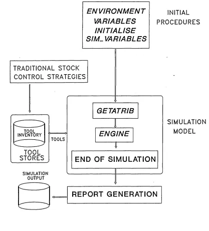
7.2 Simulation Models and Related Tool Stocking Rules 121 7.2.1 Type ’A’ Models (Without the TPS) 123
7.2.2 Type ’B’ Model (With the TPS) 125
7.3 Analysis of Results 125
7.4 Selecting a Suitable Statistical Method for Analysis 127 7.5 Method for Measuring System Performance Parameter 129
7.5.1 Data Truncation 135
7.6 Results and Discussion 136
7.6.1 Results 136
Contents
Page
APPENDIX - 1 A-l
APPENDIX - 2 A-15
1
GENERAL OVERVIEW
Tooling forms an important part of the foundation on which the new systems like Computer Integrated Manufacture (CIM) and Just In Time (JIT) are built. Many
manufacturing professionals have realised that the success of these systems is closely
tied to tooling.
The definition of tooling as given by Broom [1967] is,
”all equipment and special fixtures that the system can draw on and use during the set
up and operation o f a machine or an assembly process. ”
Melnyk [1988] groups the various items that satisfiy the above definition into three
major categories, viz; Transportation tooling, Set up tooling and Production tooling.
This indicates that Tool Management embraces many facets of manufacturing and
Chapter 1 - General Overview
1988]. Tooling is a key manufacturing resource which has been overlooked in the past. Therefore, better understanding of tooling and its features is required among
manufacturing professionals and researchers.
Any Tool Management System strives to ensure the availability of tools at the required
time, at the required place, in the correct quantity and condition [Mason, 1988].
According to Chapman [1990], Tool Management is defined differently by different
people. Tool Management is not simply the control of tool inventory, but encompasses
many diverse activities [Chapman, 1990]. These activities include Tool Transportation,
Quick Change tooling systems, Tool Identification, Tool Presetting, Post processs
gauaging systems and Electronic tool ordering system. Tyner [1988] addresses Tool
Management as the combination of problems related to flow of tools, tool presetting and
tool crib. His study included the Ergonomics (Human Factors) for safety and emphasis
on Employee Education and Training for waste elimination from the tool management
perspective. It is important that such activities are coordinated and synchronised for
achieving the objectives set out for a Tool Management System. Therefore, it seems
that it is necessary to understand the various elements of a typical Tool Management
System and establish their inter-relationships.
Traditionally, the management of tools was left to the machine operator or storeman.
The decisions on the issue of the new tools and disposal of the old ones were taken by
the operators. There were no methods of predicting the demand of different types of
Chapter 1 - General Overview
tools. This resulted in higher tooling inventory and therefore higher manufacturing
costs. About 50% of perishable tools (tools that wear out and are then disposed) in
American industries have been reported to be obsolete [Mason, 1988]. Many authors
have emphasised the problems of controlling tool inventory because this added
significantly to the cost of the product. Some industries adopted the practice of having
a central tool store as against the distributed stores. This gave an opportunity to control
the tools centrally and thereby avoiding the tool proliferation. In many organisations,
each operator had an individual tool box, which increased total volume of tools outside
the tool stores. As a result, the expenditure on these tools increased. There were no -
means of controlling this cost.
Lately, industries have realised the importance of this science. There are computerised
tool management systems available in the market, which can be implemented directly,
thereby replacing the manual tool transactions in the tool stores. However, some
industries have not been able to take the full potential of the facilities provided by these
computerised systems [Mason, 1991]. This has been mainly due to the incorrect use
of implementation methods. This research work encompasses the detailed study of a
typical tool management system and its primary functions and extends the work on tool
2
LITERATURE SURVEY
2.1 INTRODUCTION
With the advent of advanced manufacturing technologies like Flexible Manufacturing
System (FMS), CAD/CAM and CIM, new management practices such as MRP and JIT
were adopted by the industries. The new concepts such as FMS, in particular, faced
constraints in its operational flexibility due to availability of both cutting and non
cutting tools. There were other factors like tool magazine capacity in FMS which
greatly reduced its flexibility in part variety [Perera, 1988]. These problems instigated
the manufacturing professionals to develop better methods of Tool Management in
FMS. Thus, a new science of managing tooling was evolved.
A literature survey was carried out to understand the current trends of Tool
Management in manufacturing industry and problems associated with it. The science
of Tool Management (TM) is still in its early developments and many industries are not
yet aware of this potential cost saving area [Mason, 1988]. The first international
conference on TM [Michigan, 1988] shows that individual researchers identified
problems relevant to their type of business for e.g. the Airline Industry reported
problems in scheduling their critical tools for aircraft maintenance at different
Chapter 2 -Literature Survey
type of operations only (the solutions to the airline TM problems are suugested by
having a good bar coding system for tools). Similiarly, within the metal cutting
industries, different industries pay attention to the type of tooling they use most
commonly. Manufacturing processes involving large proportions of finishing (e.g.
buffing operations) require higher quantity of perishable tools, whereas, the
conventional metal cutting operations and assembly activities require higher number of
returnable (or durable) type of tools. Therefore, it is important to study the features
of different tools, on which management procedures could be developed. There is a
need to identify primary functions of TM with a unified approach. A generic structure
of TM can be constructed which would consist of these functional elements. This could
form a basis for manufacturing professionals to develop new techniques to solve their
TM problems.
Some of the causes identified by Carrie and Bititci [1988] for the failure of a typical
tool management systems include complexity of TM logistics, lack of shopfloor
discipline, lack of correct and complete information to management, lack of computer
based planning systems and incompatibility of production machines with control
equipment. Lack of shopfloor discipline led to the conflicts in coordinating machine
Chapter 2 -Literature Survey
Consequently, the literature on TM had to be classified into two major categories, viz; TM problems specific to the FMSs and TM in conventional manufacturing systems.
The following sections describe various TM problems in FMS and non-FMS and
discuss how they are different from one another.
2.2 TM RESEARCH ON FMS
The FMS allowed greater flexibility in their operations. However, it seems that in most
systems tooling constraints flexibility. These FMS constraints attracted many
researchers [Ber 1982, Falkenberg 1986, Sackett 1984, Hutchinson 1982] to develop
techniques and establish discipline for management of tools in FMS. The research on
FMS tool management increased dramatically during the 1980s. As a result, the
savings on tooling in FMS encouraged researchers to develop better methods and
sophisticated techniques (such as on-line tool information system) to solve the TM
problems. Thus tool management became a popular research topic among many
manufacturing professionals.
Kuchinic and Seidmann [1988] grouped all the tool management issues into three
categories, viz; tool specific issues, machine level issues and factory level issues. The
tool specific issues included problems like tool life, tool economics, tool standardization
and Spares Management. The Machine level issues involved tool magazine capacity
Chapter 2 -Literature Survey
constraints, automatic tool changer capabilities (ATC) and tool wear/ breakage monitoring systems. The factory management level encompasses the problems of tool
allocations to various machines, tool requirements planning, tool inventory and tool
procurement. Several researchers [Steckeand Solberg 1981, Stecke 1983, Rajagopalan
1986, O’Grady and Menon 1987] noted that short to medium term FMS production
planning must consider the limitations imposed by the tool magazine capacity. The
limited tool magazine capacity implies that proper tool allocation and scheduling
procedures must also be used in order to achieve the performance potential of the FMS.
Bao [1980], Ramlingam [1976] and Kendall [1976] addressed the problem of tool
replacement schedules in FMS. They used dynamic programming techniques to
optimise these schedules. These problems indicate the complexity of tool planning
decisions in FMS.
Amoako-Gyampah et al [1992] highlights the problem of tool allocation and tool
scheduling for the FMSs. They suggested three tool allocation strategies viz; bulk
exchange, tool migration and resident tooling. One of the important production
planning problems identified by Stecke [1983] was related to the allocation of operations
and required tooling for the selected parts among the machine groups in FMS.
Ramalingam and Balsubramaniam [1976] developed mathematical models to solve
Chapter 2 -Literature Survey
Carrie and Perera [1986] observed that the part type selection problem in FMS is one of the production planning problems severely constrained by tooling. Chakravarty and
Shtub [1984] used a Group Technology approach to solve the problems of part type
selection. They identified parts having similar machining requirements and thereby
identifying similar tooling. The capability of having alternative rerouting options for
parts make production planning in FMSs much more difficult than traditional production
lines and job shops. Ventura [1990] explained how part grouping would ease FMS
production planning problems.
Rhodes [1986] found that FMS production parameters like the number of parts and
batch operation times influenced the tool management variables like number of tools,
tool magazine capacity and tool exchanges. These parameters distinctly characterise
FMS tool management requirements.
Ranky [1986] stressed the need for an integrated tool database for FMS real time
control. Tool management involves a variety of activities which makes it essential to
have on-line information for the dynamic environment. His study showed that each
FMS needs tool management tailored to its requirements.
Chapter 2 -Literature Survey
2.3 USE OF FMS TOOL PLANNING TECHNIQUES FOR CONVENTIONAL
MANUFACTURING
Researchers have developed few methods of planning tools in FMSs. Perera [1991]
highlighted one of the major differences between conventional manufacturing and FMS.
Formal planning systems steer the events in FMSs. A detailed preplanning system is
essential to ensure the uninterrupted flow of parts within the FMS. It is also important
that real time data is available to overcome the tool planning problems in FMS.
Perera’s [1988] tool flow simulator provides some visibility into expected tooling
shortages within FMS environment.
The tooling problems like tool flow, tool exchanges, tool magazine capacity etc. are
usually not found in conventional manufacturing, unless it is a very highly automated
production system with facilities like automatic tool transportation, automatic tool
changing systems or automatic part loading. Tooling information is stored centrally in
the FMS executive computer. There is no real time data available through such central
computer in conventional manufacturing. Therefore, many of the TM techniques such
as tool allocation strategies and tool flow using simulation do not apply to traditional
systems. These features of manufacturing are found only in FMS. Hence, it is not
Chapter 2 -Literature Survey
attention to FMSs. As a result, there are very sophisticated techniques now available
for FMSs, but the TM in traditional systems is still in its embryonic stage. Therefore,
there is a need to have better TM techniques for conventional systems.
2.4 TM RESEARCH FOR CONVENTIONAL MANUFACTURING
The first evidence of work found on TM in conventional systems consisted of the
mechanism of a generic tool control system. Galligan and Mokris [1981] modelled the
mechanics of a generic structure of TM Information System. They identified functional
requirements of an integrated tool control system and grouped into three major
categories, viz; Tool Inventory Control, Engineering Change Control, Tool
Consumption and Cost Control. However, it appears that the planning aspects of tools
were not developed at that stage. These facilities were designed and incorporated on
a computerised system. They also developed the tool data system which would provide
information such as tool master, tool purchase, tool transactions and tool consumption.
They suggested the option of designing the central tool database from where the
appropriate information could be provided to the required places. It is now widely
accepted that causes of many TM problems are centred towards database management
systems [Galligan et al, 1981]. The detailed discussion on TM database management
systems is available in Chapter 5.
Chapter 2 -Literature Survey
A typical TM in conventional batch manufacturing system may involve all kinds of *
activities from the stage of tool purchase to tool maintenance and tool disposal. Long2
[1991] lists some of the TM activities, which are as follows.
Tool Engineering Tool Design
Tool Procurement Tool Rework
Tool Inspection Tool Storage
Tool Presetting Tool Accountability
Tool Planning Tool Inventory Control
Ideally, every TM system should be capable of performing the above mentioned
functions. Due to the range of activities involved in any TM system, it is difficult to
co-ordinate them and in many cases, it is usually beyond the capacity of human control.
Additionally, the variety of tooling makes it even more difficult to manage them,
because different types of tool need different management procedures. It is, therefore,
necessary to define what primary functions are required by any formal TM system and
how these functions relate to other functions of manufacturing. The survey indicated
that no researcher in the past has made any attempt to establish the exact structure of
TM applicable to conventional manufacturing system. Due to the complexity of TM
Chapter 2 -Literature Survey
Weimer 1983]. These techniques are linked with the CAD/CAM to save the costs incurred in inappropriate selection of tools.
Melnyk1 et al modelled the simulation of a machine shop with machines and tools. The
work was focused on the impact of an alternative tooling assignment rules on the
operation of the shop, with varying levels of tool availability and job priority rules.
This study was related specifically to tool assignment rules.
Besides the above work in conventional manufacturing, only Wassweiler [1982] gave
a new approach called Tool Requirements Planning (TRP). This method determines the
tooling requirements from the process plans and schedules them in accordance with
production schedules. The technique can schedule the critical tools on hourly basis.
The tool allocation schedule is very precise, however, this system is limited to heavy
fabrication shops of the make to order type with very high product variety and low
volumes. It is most suitable in heavy fabrication type environment, where special tools
(usually more expensive than standard tools) form a limited resource and where sharing
of such tools is more frequent.
The need for an alternative approach to planning tools for batch manufacturing arises
due to the four basic differences in the features of these two production environments,
which are laid out in the following table. This has significant influence on the planning
procedures.
Chapter 2 -Literature Survey
System Features Heavy Fabrication Batch Manufacturing
Product Variety Very high Medium
Production batch size Very small, usually one Large
Planning Horizon Large (months/years) Short (days/weeks) Type of tools used High usage of multiple
and complex tooling. Requires tool assembly and kitting.
High usage of single tools.
In Wassweiler’s Tool Requirement Planning (TRP) method, the tools are scheduled in
line with the part schedule. The tools are allocated to a single job and the
manufacturing lead time of such jobs in heavy fabrication is usually longer than the jobs
in batch manufacturing. Allocation of tools to individual jobs is not feasible in batch
manufacturing because the production lead time of components is small. Hence, an
alternative approach of allocating tools to the batches rather than the individual
components is required.
Usually, there is a higher usage of simpler and single tools in high volume batches,
which requires a different method than that for complex multiple tools. The TRP
accounts for tools requiring assembly, which uses the concept of a Bill of Tools (BOT)
similar to a Bill of Material (BOM). The BOT concept is used for scheduling the tool
Chapter 2 -Literature Survey
Since the batch sizes are usually larger in batch manufacturing, the demand of certain
tools is on a regular basis as against the unpredictable demand in heavy fabrication.
This feature will have a significant impact on the tool planning strategies and the
associated tool planning methods. Therefore, the TRP method can not be used in batch
manufacturing.
There are MRP type methods available for planning and allocation of material. It is
necessary to understand why such techniques cannot be used for tool planning. Melnyk
[1989] has identified the fundamental characteristics of tools. It is like material which
can not be used at more than one place. Secondly, when the tool is returned to the
stores, there is no change in its stock quantity, but its total tool life has decreased. In
other words, the process capability of tool has decreased.
Therefore, the tool planning technique should consider both the above characteristics.
A hybrid approach of classical stock control together with the logistics that would
account for the tool life can be used to plan the tools. In order to develop such a tool
planning system, information from various external functions such as Process Planning
and Production Planning is required to carry out the necessary data processing.
It can be summarised that there is a lack of work on tool planning techniques, in
particular, which would be applicable in batch manufacturing environment. However,
there are commercial TM software packages available, which perform basic TM like
Chapter 2 -Literature Survey
issue, return and stock holding. The discussion on the TM software is given in the
following section.
2.5 DEVELOPMENTS IN TM SOFTWARE
Allock [1986] reports that Siemens developed a software for a Flexible Manufacturing
Cell (FMC) that comprised a module for tool requirements. For every new job, before
loading, the gross requirements including the remaining tool life are identified to ensure
the completion of jobs. It is claimed that the system is on-line, as it computes the net
requirements for the next job immediately after the completion of the first job.
However, this article does not clearly explain exactly how the tool requirements are
identified. Additionally, it lacks explanation on tool life estimation for individual tools
on the part type basis. Usually, in an FMS environment, the machining content of jobs
will vary significantly from one part to another. Unless very sophisticated methods for
predicting tool life consumption are used, it is very difficult to ensure the job’s
completion.
Electronic Data System (EDS) (a Software House) is assisting General Motors in
Chapter 2 -Literature Survey
presetting, identification, inventory control and tracking. Mason [May 1991] lists several software houses supplying dedicated tool inventory and tracking software.
Some of these software include, Cribware, TMS-2000, ATICTS, ITC’s Toolware, Tool
Location Control and Microtoolware, Kavon’s Cribmaster, SpaceSaver’s TCS, Sycon’s
PC-Toolcrib.
Our survey of software houses supplying commercial computerised tool management
system included Amazon’s CTMS and Cincinnatti Milacron’s TMS-2000 and Tooltrak.
TMS-2000 offers facilities like Inventory Control, Bill of Tools, Purchasing information
(details of tool suppliers) and Gauge Control. The additional module Tooltrak, provides
facility to locate the tools, assign the critical tools to the workcenter or the product and
keep the track of individual tool usage or rate of consumption. It also allows you to
set the tool reorder level to maintain the required inventory levels.
Amazon’s CTMS provide the facilities for tool transactions (issue and return), allows
you to build the tool kits and generate the Bill of Tool (BOT) structure with kits and
assemblies, generates the Purchase Requirements based on the current inventory levels
and the reorder levels. It also offers facility for recording the details related to tool
presetting, tool calibration and tool inspection.
It appears that the above software offer facilities that are important to achieve tool
stores and to some extent tool stock control requirements. However, none of them
Chapter 2 -Literature Survey
provide a facility to plan and schedule tools based on the master schedule. It is realised that there is a need to bridge a gap between Production Planning and Tool Management
through a Tool Planning function.
2.6 PROBLEM DEFINITION
The aim of the research programme is to develop a tool planning system fo r batch
manufacturing.
There are two major problems in batch manufacturing that are associated with tooling.
One is the excessive tool inventory in tool stores and the other is the production
stoppages due to unavailability of tools. These problems indicate that tools are either
not used to the fullest extent or not planned properly. Although, tool stores records
show that they are available, it is not known where they are located and in what
condition. This often leads to expediting tool purchases and thus increasing the
inventory. Therefore, methods for planning the tools on the basis of Production Plans
need to be developed. It is essential for any tool management system to have a
mechanism to plan tools in order to ensure their availability. This work explores such
3
FUNDAMENTALS OF TOOL PLANNING
3.1 INTRODUCTION
The manufacturing industries of the 80s used Material Requirement Planning (MRP)
type planning system in the batch manufacturing environment. The factory schedules
were created based on forecasted demand, backlogs or safety stock levels, inteiplant
orders and customer orders. The resources such as men, machines and material were
taken into account by production planning but tooling was neglected.
The availability of tools is of paramount importance for the smooth running of
production according to production schedules. It is, therefore, necessary to include
tooling as an additional resource in the process of production planning. This means
that, while developing an MPS, if the tools are accounted for, then the formation of the
MPS will be influenced by the tooling. Hence, it is essential to study the effect of new
TM techniques on the MPS which can be achieved by integrating MRP-II with the TM.
Tool Planning froms a prominent element of any TM system.
Having understood the importance of tooling in manufacturing control, it is then
necessary to see how such a resource can be linked/integrated with other production
Chapter 3 -Fundamentals of Tool Planning
Manufacturing Resource Planning (MRP-II) ? Can the MPS be created on the basis of tooling availability ? or the tools to be planned according to the MPS ? Figure 3.1
shows the complexity of tool planning decisions in the context of MRP-II. Fig 3.2
shows the role of Tool Planning in MRP-II environment. This chapter will discuss such
a possibility of bridging the production planning function with the TM and highlight the
advantages by doing so. An attempt has been made here to construct the generic
structure of a typical TM system with its primary functions.
3.2 SELECTING A SUITABLE TECHNIQUE FOR ANALYSING THE TM
SYSTEM
In order to develop methods for planning tools, it is necessary to study the various
functions of a TM system, their inter-relationship and their relationship with other
functions of manufacturing such as CAD, Production Planning and Process Planning.
There are methods available for analysis of complex systems, such as ICAM definition
methods (IDEFO and IDEF1), Structured Design Method (SDM) which is principally
based on Jackson Structured Programming (JSP) and Structured Systems Analysis and
Design Methodology (SSADM) which is derived from SDM.
Chapter 3 -Fundamentals of Tool Planning
adopted by many organisations and has become the leading system analysis and design
method in the U.K. AUTO-MATE is a Computer Aided Software Engineering (CASE)
tool, which has now been widely used for systems analysis and design. It was
originally developed by Learmonth and Burchett Management Systems (LBMS) in the
U.K [LBMS]. SSADM in conjunction with AUTO-MATE was an ideal choice and
hence, it was selected for this study.
In this work, primarily two analysis techniques from SSADM are being used, which are
the Functional Analysis and Data Analysis. The functional analysis gives a thorough
understanding of the various functions of TM system and its relationship with the other
manufacturing functions. The data analysis gives the database specifications for the
required system (in our case it is the TM system) in a normalised form (Data Analysis
and normalisation is explained in chapter 4).
3.3 FUNCTIONAL ANALYSIS
Functions or activities need certain information to achieve their objectives. The analysis
is carried out top down, level by level. High level functions being identified first with
lower levels being introduced by successive functional decomposition [Cutts, 1987].
The functional analysis produces what is known as the ’Data Flow Diagram (DFD)’.
The DFDs contain the functions, sources of data flow, destinations of data flow and
Chapter 3 -Fundamentals of Tool Planning
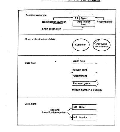
data stores. Figure 3.3 shows the diagram conventions used in DFDs. The DFDs represent the user’s view and therefore fully understandable by the user. Hence, there
are no fixed rules governing the number of functions that should be shown on a single
DFD.
From the higher levels or level 1, the functional decomposition provides more detailed
information by zooming in on any or all of these rectangles. Some functions may have
more levels than others. The picture of such a decomposition is shown in Fig 3.4. The
meaning of various objects used in creating DFDs are explained below.
(1) Functions
Functions are represented by rectangles and form the dominant feature of DFD.
Each function is given an identification number, a single number at level 1 and
compound numbers at subsequent lower levels. The respective authority
responsible for this function is associated with this identification number. A
short description of actual activity is given in the rectangle.
(2) Sources and destinations for data
Ellipses represent external functions. Each ellipse may be used at more than
one place in a single DFD. In order to show that there is more than one ellipse
Chapter 3 -Fundamentals of Tool Planning
(3) Data flow
Data flows are represented by arrows. Each arrow represent the flow of data element with its unique name. The single headed arrows means flow of data in
one direction, whereas, double headed means data flow in both directions. The
physical movement of tools is not shown on DFD, however, it is important to
understand how the data related to tool movement is generated and flows
through the system.
(4) Data stores
These are represented by open ended rectangles. They represent files, private
reference books or any form of data store within the system. Each data store
has a name and is associated with its unique identification. A double bar at the
closed end of the rectangle indicates that this data store is repeated elsewhere
on the DFD.
With the help of the above conventions all the required DFDs were created. The
following section gives the overview of the TM system from the information system
point of view (from Figs 3.6 to 3.9).
Chapter 3 -Fundamentals of Tool Planning
3.4 INTERACTION OF TOOL MANAGEMENT WITH OTHER FUNCTIONS OF
MANUFACTURING
The process of analysis begins by creating the ’Context Diagram’ (at level ’O’). This
DFD specifies the scope of the system (which is TM, in this case) by defining its
boundary within the focused environment. In this case, the boundary of TM system is
identified within the conventional/batch manufacturing environment (Fig 3.6).
The major manufacturing functions interacting with the TM system are Production
Planning, Process Planning, Purchase Department, Computer Aided Design - Computer
Aided Manufacture (CAD/CAM), Shop Floor Control and Tool Supplier. All these are
treated as external functions.
Functions like Purchase and Tool Supplies may or may not be included in the TM
system depending upon the working practices of the organisation. For example, Tool
Requisition function can be treated either independently or as a part of other General
Purchases. Similarly, tool suppliers are treated external to the TM system of the
organisation, because each supplier has his own tool catalogue and in practice, the TM
system may buy different tools from different suppliers.
Chapter 3 -Fundamentals of Tool Planning
the TM and other functions would be valid for any ideal TM. The relationship between
the six external functions (as identified earlier) and TM is discussed below.
Production Planning informs TM about the proposed MPS together with the aggregate
production plans, if any, and receives the report about the feasibility of such an MPS
from the viewpoint of tooling availability.
Shop Floor Control (SFC) has close interaction with TM, where SFC keeps the tool
consumption records (or historical records) on either the basis of workcenter or the
production order, as the case may be.
CAD can play a prominent role in TM. The new and existing products can be designed
in such a way that the existing tooling can be used to fabricate them. This is also
known as Tool Variety Reduction in TM terms.
Ideally, CAD should have an access to Tool Master Database to know the already
existing tools or most commonly used tools for certain operations. Additionally, all the
new tools introduced by either Tool Engineering Change Control (a function of TM)
or newly required, as specified by CAD (e.g. form tools for special geometries) need
to be included in the Tool Master Database.
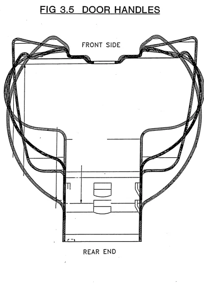
Such measures for tool variety reduction have already been undertaken by an American
multinational. Fig 3.5 shows a range of product variety (Door Handles) with identical
Chapter 3 -Fundamentals of Tool Planning
geometric features. Any changes in the front end shape would require a new type of tool (in this case, different form tools will be required by different components from
the high volume production point of view). Small modifications in the geometry of the
front end have resulted in tool variety reduction by more than 50% for that family of
components, without sacrificing their functional aspects.
Tool Procurement can be conducted by sending the appropriate tool requirements to the
Purchase Dept. In return, the Purchase Dept, can inform the expected date of tool
receipts and delivery details to the TM, which would assist TM in planning the tools.
Similarly, the tool purchase cost database can be maintained by Tool Purchase Dept.,
which would be useful for both tool costing and tool budgeting purposes.
The information such as Tool Master Database (which would ideally contain
information on tool specification) is essential to process planners to make the machining
processes (or fabrication, as the case may be) more effective by selecting appropriate
tools. In return, the TM can have an access to information about the part details (like
part number) for which the tools are being selected. This would facilitate the TM to
establish the relationship between the part types and associated tool consumption.
Usually, a tool purchase engineer (also termed as ’Tool Liaison Engineer’) develops and
Chapter 3 -Fundamentals of Too l Planning
3.5 FUNCTIONS OF TM IN CONVENTIONAL MANUFACTURING
Having drawn the boundary of the TM system (in Fig 3.6), it is then decomposed into
various functions of TM at the next level which is level *1* (Fig 3.7). All the external
entities identified at level ’0’ and the related data flow is retained at this level.
The functions of TM are also represented by rectangles. The data flow from or to the
external entities is connected to the newly created functions. The additional flow of
data between the functions and the data stores was drawn and the final DFD was
produced (Fig 3.7).
All the activities related to TM were grouped into five major functions and each
function was assumed to have certain responsibilities. These are listed below,
(1) Tool Store Services
(2) Tool Planning
(3) Tool Requisition
(4) Tool Engineering Change Control
(5) Tool Inventory Control
Major functions listed above at level *1* which were then decomposed into sub-
fimctions at level ’2’ (Fig 3.8 shows the Tool Store Services and Fig 3.9 shows the
Tool Planning). Other functions were not decomposed as the focus of the research was
Chapter 3 -Fundamentals of Tool Planning
on Tool Planning. The details of the activities involved to achieve the objectives of these functions are stated in the following sections.
(1) Tool Store Services
;-The basic activities that any tool store would be responsible for are,
(a) Issue, return, storage and transport of tools
(b) Keeping the record of location and the condition of tools.
(c) Inspection of new and used tools before storage.
(d) Updating the stock details.
(e) Generate tool consumption information (for consumable) from tool usage
data received from shop floor and update tool history records (in case of
returnable).
(f) Sending the requisition for the purchase of "C" class tools.
(g) Follow up of tool preparation schedule.
(2) Tool Planning
Tool Planning is anticipated to have the following sub-functions.
Chapter 3 -Fundamentals of Tool Planning
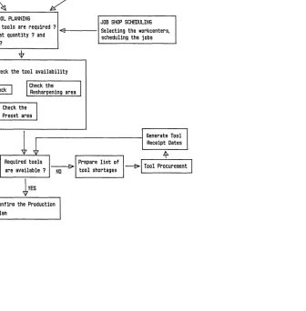
availability and informing the Production Planning Department about the tooling
shortages.
(f) Schedule the critical tools according to the job order, and plan the tool v
preparation activities. Generate any necessary tool preparation schedule and
send it to the Tool Store Services.
(3) Tool Requisition
Traditionally, tool purchase activities fell under General Purchase Department.
However, in this study, they are considered as part of tool management as this assisted
in studying the relationship between tool requisition and other functions of tool
management. The functions of this department are,
(a) Generate Purchase Orders for tools on request from tool requisition list.
(b) Keep the updated record of tools ordered, expected date of receipts and
provide to the tool planning with the tool awaiting list.
(c) Compile the tooling costs and maintain tool cost database to be used by tool
inventory control.
(d) Evaluating the tool suppliers for their service.
(e) Liaising with the tool suppliers and develop relationship with the suppliers.
Chapter 3 -Fundamentals of Tool Planning
(4) Tool Ennineerine Change Control
;-This department will be mainly responsible for controlling the changes in the design of tools which may occur either due to the product design change or the changes in the
efficiency of the machining processes (or process capability). When such changes take
place, better control is required for the successful introduction of new tools. The main
objectives of this function are stated below.
(a) Decide the application area of the tools.
(b) Coding and classification of new tools on the basis of their engineering
specifications.
(c) Define the tool structure and enter the tool kit details into the Bill of Tool
(BOT) database.
(d) To estimate the total tool life on the basis of their engineering specification.
(e) To specify whether the tool should be purchased or fabricated in-house.
(5) Tool Inventory Control
;-There is always a trade off between the investment in maintaining the tool inventory
levels and the cost of administering the manufacturing resources to run the production
Chapter 3 -Fundam entals of Tool Planning
(a) To develop a mechanism to make the decisions regarding: o Lot size of orders
o Setting appropriate reorder and safety stock levels (This factor is
important to maintain the stock levels of perishable and semi-perishable
tools.)
o Procurement lead time of tools
(b) Use tool store capacity information to develop inventory control strategies.
(c) To carry out detailed A-B-C analysis of tools from the tool cost database.
The earlier section gave a general overview of the TM functions and their relationships.
The successful operation of any TM system depends on how well the information is
made available to these functions and the logistics of their data processing to make the
desired TM decisions. This shows the complexity of decision making process in TM.
It was anticipated that the benefits of researching in tool planning methods were direct,
significant and practical. A Tool Planning system would aid in checking the feasibility
of production schedules, developing inventory control strategies and assist in tool
budgeting. The following sections gives an overview of tool characteristics that can aid
in establishing the fundamental principles on which a tool planning system could be
built.
Chapter 3 -Fundam entals of Tool Planning
3.6 TOOL CLASSIFICATION
The ideal tool planning system would consider all types of tools. It is seen that different tools are used for different purposes and therefore have unique characteristics.
Cutting tools are used to cut metals (eg HSS bars, inserts) and used on the machine
until the end of the machining process, whereas non-cutting tools play different role.
They could be used for setting up the process (set up tools) or holding the workpieces
(eg jig & fixtures). Hence, it is essential to classify the tools on common attributes and
study how such attributes would influence the Tool Planning methods.
The non-returnable tools (also known as ’disposables’) have a very short life cycle in
TM system. By definition, they are thrown away and not reused or returned to the
stores. The management of such tools would be simpler than the retumables.
On the other hand, the returnable tools are retained by the tool stores upon satisfactory
inspection of their condition. The retumables exist longer than disposables in any TM
system and therefore, the planning of these tools becomes difficult. Very often, at any
given time, the location and condition of retumables is not known. The transactions
(issues/returns) at the tool stores take place more than once with retumables and the
tool life normally decreases after each transaction. Therefore, better planning methods
Chapter 3 -Fundam entals of Tool Planning
The non-cutting tools can be either treated as retumables or can be permanently assigned to the workcentres. These would need different planning and allocation
procedures.
Tools are normally grouped according to their functions for the purpose of selecting the
required machining operations (drill for drilling, mill for milling), but for planning and
control, they may need to be classified on different criteria. Many researchers classify
tools to suit the requirements of their business needs [Galligan, Meister, Boyle,
Kupferberg-1981, Melnyk-1988]. Some of the criterion that were used are listed
below,
(1) Functional Classification : The tools are classified on the basis of the purpose for
which they are built.
(a) Cutting tools
(al) Retumables or reusables
(a2) Non-retumables or disposables
(b) Non-cutting tools, for e.g.
(bl) Set up tools
(b2) Jig & Fixtures
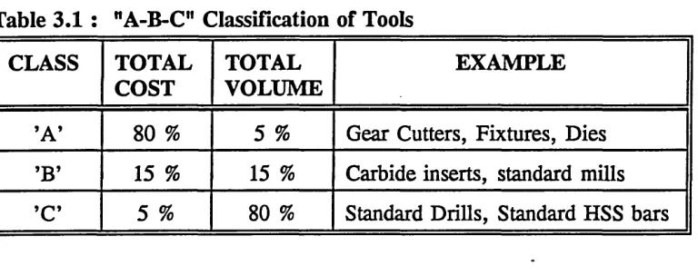
(2) "Cost/Volume R atio: Some tools require tighter control than others. The "A-B-C"
classification is a well known technique that help in controlling higher value tools
Chapter 3 -Fundam entals of Tool Planning
tighter than lower value tools. The "A-B-C" classification based on the cost/volume
[image:42.615.88.472.159.311.2]ratio is explained in Table 3.1.
Table 3 .1 : "A-B-C" Classification of Tools
CLASS TOTAL
COST TOTALVOLUME EXAMPLE
’A’ 80 % 5 % Gear Cutters, Fixtures, Dies ’B’ 15 % 15 % Carbide inserts, standard mills ’C’ 5 % 80 % Standard Drills, Standard HSS bars
It can be seen that ’A’ class tools carry higher value than ’B’ class and therefore need
tighter control. Savings on few ’A’ class tools means significant savings in tool
inventory costs. ’C’ class tools have low values and therefore do not need greater
attention. The limits for the ’A-B-C’ classification are usually set on the basis of
company’s inventory policy.
(3) Flexibility of use : Some tools can be classed as either standard or special purpose,
based on the range of their applications.
(a) Standard Tools :- Their design is standardised and they can be used for
Chapter 3 -Fundamentals of Tool Planning
also known as dedicated tools. They could be assigned either to the specific
workcenters or products/ product groups.
(4) Procurement Lead Time : Tools can also be classified according to their
procurement lead time. Although many tool manufacturers deliver orders within a few
days, there are some tools with special requirements which can take longer than the
standard delivery time. Those with higher lead time can become critical or limited
resource and therefore would need advanced planning methods.
3.7 FUNDAMENTALS OF TOOL PLANNING
In repetitive manufacturing, the practice of using classical stock control techniques was
common for all types of tools irrespective of their characteristics. Since different tools
have different features, they require different planning approaches. There is no single
rule that can be applied to plan and control all types of tools. This often led to
excessive stock and obsolete tooling. Therefore, a hybrid approach of using a suitable
technique for each type of tool is required.
The principal criterion of Material Requirement Planning (MRP) applicability is the
existence of Master Production Schedule (MPS) to which raw material procurement,
fabrication and subassembly activities are geared [Orlicky, 1975]. Similarly, a valid.
MPS is the prerequisite to execute any tool planning procedures. In the same way as
Chapter 3 -Fundamentals of Tool Planning
MRP is applicable to any discrete item purchased or manufactured that is subject to dependent demand, Tool Planning should be applicable to any tools purchased or
fabricated in-house that is subject to dependent demand.
An approach similar to Production Planning can be considered for Tool Planning. The
tool planning can be hierarchically structured similar to MRP system. Perera [1990]
suggests such an approach applicable to FMS. This involves Aggregate Tool
Requirements Plan (AGG-TRP) at the highest level indicating the effect of aggregate
production plan on value and volume of tooling for long range planning. At the
intermediate level, a rough cut capacity plan is suggested which considers only key
tools to meet the requirements of provisional MPS. At the bottom level, Perera [1990]
suggests a simulation based Tool Requirement Planning (TRP) running on MRP
outputs. However, there is no relationship between AGG-TRP and rough cut tool
capacity plan or between rough cut tool capacity plan and simulation based TRP. In
other words, there is no vertical link between these tool planning activities.
This research proposes a hierarchical tool planning approach similar to the above but
with only two planning levels, viz; AGG-TRP at the top level and TRP at the bottom
level. The concept of rough cut tool capacity has been eliminated as the AGG-TRP can
be used as a guideline for confirming the feasibility of provisional MPS. The proposed
Chapter 3 -Fundam entals of Tool Planning
horizontal interaction with the production planning hierarchy.
It is not feasible to make use of Perera’s [1990] simulation based TRP for batch
manufacturing. This is due to the lack of data needed for simulation, which is normally
readily available in FMS executive computer. However, a TRP generated from the
outputs of MRP has been used in this research. Further explanation on the tool
planning methodology used can be made available from chapter 4 and 5.
The problem of tool planning can be partially resolved, if the total tooling requirements
can be estimated on the basis of information available in MPS. The total tooling
requirement can be defined as a set of three basic questions, viz; ’WHAT* tools, in
’WHAT QUANTITY’ and ’WHEN’. Ideally, any Tool Planning system should be
capable of answering these questions. Once the total tooling requirements are
determined, then the tools can be planned in time buckets. This would give TM a
better view of expected level of tooling activities over the respective planning horizon.
This can also be termed as 'Off Line Tool Planning'.
The information required from external sources to carry out tool planning procedures
can be described with a diagram as shown in the fig 3.11 (offline tool planning). The
appropriate information can be obtained from Process Planning, Tool Engineering and
Production Planning to provide answers to three major questions for tool planning.
The process plans usually specify the sequence of operations and the respective tools
Chapter 3 -Fundamentals o f Tool Planning
required to perform them. Thus, exactly ’WHAT’ tools are required can be found.
The information such as tool life can be obtained from tool engineering (tool
specification) details. This in conjunction with actual machining requirements can
provide a rough estimate of tool life consumption. Thus, the tool quantity (’WHAT
QUANTITY’) can be known on the basis of the quantity of the components to be
produced (which are at the lowest level of Bill of Material (BOM) structure).
The MPS gives a plan of end products to be produced in a time bucket. Once ’WHAT’
and ’in WHAT QUANTITY’ are answered, they can then be related to the end products
from the BOM. Thus, the total requirements can be planned in the same sized time
buckets as used in the MPS. This can also be termed as "Aggregate Tool Requirement
Plan". The manufacturing lead time is taken into account to calculate the time
’WHEN’ the tools are required. Once the tools are planned in time buckets, then they
need to be allocated to either planned production orders or respective resources such
as workcenters.
To achieve the objectives of tool planning i.e. determining tooling requirements and
allocating tools, tremendous amounts of data need to be collected, processed and finally
interpreted. The Data Flow Diagrams created earlier gives the data elements and data
files to carry out the activities or functions. Such data files provide exactly what
Chapter 3 -Fundamentals o f Tool Planning
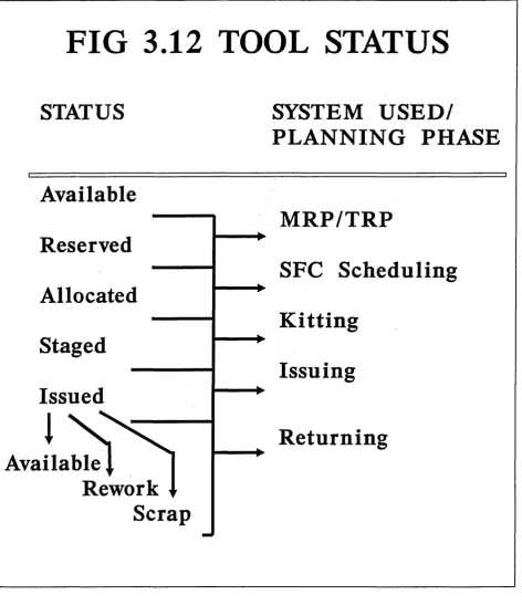
Fig 3.12 shows the changes in the status of tool as we come closer to the tool required date. This also describes the necessary tool management activities that are associated
with the status of the tool. This research will be mainly focused on the first part, which
is tool planning. However, the second part, i.e. tool allocation procedures (section
4.2.3) is not discussed in detail. The following chapter extends the discussion on tool
planning and illustrates the proposed tool planning methodology.
FIGURE 3.1 COMPLEXITY OF TOOL PUNNING DECISIONS
t
n
w
u
«c
r
S
t
n
[image:48.615.236.573.134.489.2]C h a p te r 3 -F u n d a m e n ta ls o f T o o l P la n n in g O z
<
LU O CO I— CO < o LU CC O U_\
V v V < z O CO CO CL > O CC Q_ Oo
LUChapter 3 -Fundamentals of Tool Planning
FIG 3.3 : DFD Diagram Conventions
Function rectangle
2.7 Typist
Responsibility Identification number Type invoice
form Short description
Source, destination of data
Accounts department Customer
Credit note Data flow
Request card
Appointment
Returned goods
Product number & quantity
Data store
M1 Order Type and
identification number
[image:50.613.62.466.134.578.2]Chapter 3 -Fundamentals of Tool Planning
M
ia
C h a p te r 3 -F u n d a m e n ta ls o f T o o l P la n n in g
FIG 3 .5 DOOR HANDLES
FRONT SIDE
[image:52.612.86.502.107.703.2]<5ri m CJf5
CD
Fig 3.7. Level '1' DFD
Chapter 3 -Fundamentals of Tool Planning
O f c > c C 2
<0 CL jp O X
.2
O)
c
c
c
<0
>
<L -g
g <5
O u<p ° T
D
o
E o- <D DC ■i= HD w
CT C
S’ CD
D) D) •c0 <sQ w . Cl Q . <0 Q . a1 So <*» oOQ
o
-co o v. Q. Q. qj c: *0 X31
Q. £CD
i_ D -#—» O 13 i-CO
ac
■ M
C
C
_c
0 Q_ T o o ■JZ
o
1_CO
1_Q)
m S H H
Ch apter 3 -Fu n d am en tals of To o l Pla n n in g
CO \ / 2 CL U $> O ^ / \ d
LU
Cv
U.
ill!
u
VzLLI
X
5
Z
<
Chapter 3 -Fundam entals of Tool Planning
FIG 3.12 TOOL STATUS
STATUS
SYSTEM U SED /
PLA N N IN G PHASE
Available
M RP/TRP
Reserved
SFC Scheduling
Allocated
K itting
Staged
Issuing
Issued
Returning
Available
Rework
Scrap
[image:59.614.34.507.82.640.2]4
TOOL PLANNING METHODOLOGY
4.1 INTRODUCTION
Having understood the fundamental principles of tool planning in the earlier chapter,
it is important to see how a generic method for planning can be designed using these
principles. The proposed Tool Planning Methodology based on the findings of the
literature published by the various manufacturing professionals is laid out in detail in
this chapter. The various stages of suggested planning activities are explained and the
theory required for constructing a computerised tool planning system (TPS) is developed
here. This chapter is concluded with the anticipated benefits and limitations of the
proposed TPS.
4.2 TOOL PLANNING METHODOLOGY
Chapter 4 - Tool Planning Methodology
vendor or fabricated in-house) at different time phases and synchronize
the tooling activities required for ensuring tool availability.
Step 3 : Allocate these tools to the respective production orders within the time
buckets.
4.2.1 - Step 1 : Deriving the Tool Requirements in Time Buckets
The MPS stipulates the planned production (of end products) in either weekly or
monthly time buckets. The MRP explodes the Bill of Material (BOM) to the lowest
level of product structure. The Planned Order Release (POR) date of these individual
components is set by back scheduling or by adding the respective manufacturing lead
time. Thus, the MRP gives the POR dates and the net requirements of these
components. Usually, certain types of components are bought out and others are either
fabricated and/ or assembled in-house.
Each of these items have a unique process plan, as created by the process or production
engineers. This gives the sequence of operations and the list of respective tooling
required for those operations. The plan also gives the detailed information on the
machining requirements and the type of workstation required. This answers ’WHAT’
tools are required. The tools as identified from the process plan are linked to the tool
information in Tool Master Database’. This database has a key field called ’tool
code’, which enable access to the various details about the tool, such as the ’A-B-C
Chapter 4 - Tool Planning Methodology
class’, ’the procurement lead time’, whether ’standard or special’ tool and whether ’cutting or non-cutting’ tool.
The next question ’HOW MANY OF EACH’, would apply mainly to cutting tools. In
case of non-cutting tools the problems are associated with availability and allocation
more than knowing the exact quantity of each type of tool. The tool planning would
attempt to answer only WHAT and WHEN for non-cutting tools. The synchronization
of tooling activities with such tools are explained in steps 2 and 3.
Consider the cutting tools for calculating the tool quantity is required on a production
batch size basis. In order to achieve this task, information such as estimated machining
time of each operation and estimated tool life (in hours) of each required cutting tool
is essential.
Tool quantity = (MacMninS time) * ( * * * [5.1]
Tool life
This gives a rough approximation of the number of tools required or the number of
resharpening occasions of the tool. The issues related to the above equation are
Chapter 4 - Tool Planning Methodology
Aggregation o f tooling quantity in time buckets :
Usually, the time phasing of MRP shows more than one component produced in a given
time bucket. The tools that are common to these components need to be added in order
to calculate the total tool quantity requirements. Thus, the entire range of exploded
BOMs of different end products can be accounted and total tooling requirements can be
accrued.
This can be explained by an example. Consider an end product ’A’ which has the
product structure as shown in the fig 4.1, ’B’, ’C’ and ’D’ are the sub assemblies,
whereas ’E’ and ’F’ are the components that are fabricated or manufactured in-house.
The number with these alphabates (e.g. E-l) represent the quantity of each item
required to make the assembly or sub assembly of items at higher level.
Let’s assume that components ’E’ and ’F ’ are required to be machined and cutting tools
of consumable nature are involved in the process. The MRP explodes the BOM
structure and determines the material requirements in time buckets (say weekly in this
case). A typical plan is given in the Table 4.1. The components ’E and ’F ’ are
produced from week #4 till week #8.
Chapter 4 - Tool Planning Methodology
Table 4.1 : MRP in weekly time buckets.
WEEK
Component 4 5 6 7 8
A 1200
B 400
C 1560
D 1530 1200
E 1500 1200 2800 270 380
F 1490 4320 800 270
As explained earlier, the Step 1 produces the tooling requirements of individual
components. Once this is established, all the tooling requirements are scanned for
common tooling. If more than one component with common tooling requirements are
planned to be produced in the same week, then such tooling quantity is added. In this
case, the quantity of common tooling for ’E’ and *F* is added for each of these weeks
(i.e.; the week # 4,5,6 and 7) and the total requirements are calculated for product ’A’.
However, Whitney and Gaul [1985] have noted that the tooling constraint is not of the
usual linear form. Tool requirements for the parts are not necessarily additive with the
part types in batch. Different part types may use identical tools and can share those