Neural Network and Genetic Algorithm Based Finite
Element Model for Optimal Die Shape Design in
Al-1100 Cold Forward Extrusion
Abdul Kareem Flaih Hassan, Raad Jamal Jassim, Mustafa Muneam Jafaar
*Department of Mechanical Engineering, College of Engineering, University of Basra, Iraq
Copyright©2016 by authors, all rights reserved. Authors agree that this article remains permanently open access under the terms of the Creative Commons Attribution License 4.0 International License
Abstract
This paper employs rigid-plastic finite element DEFORMTM 3D software to estimate the plastic deformation behavior of an aluminum billet during its axisymmetric extrusion through a conical die. The die and container are assumed to be rigid bodies and the temperature change induced during extrusion is ignored. The important parameters which effect on the extrusion process were assumed to be: the reduction of area (0.75), semi- cone die angles (5, 6, 7, 8, 10, 12, and 14o) coefficient of friction is 0.05 and the extrusion speed is 250 mm/s. Under various extrusion conditions, the present numerical analysis estimates the stresses, the die load and the flow velocity of the billet at the die exit. Genetic algorithm coupled with neural network is employed to find optimum die angle leading to minimum stresses without any constraint. The simulation results confirm the suitability of the current finite element software for modeling the three-dimensional cold extrusion of aluminum rod.Keywords
Extrusion, Die Angle, Stress Distribution, Aluminum Rod1. Introduction
Forward extrusion is a forming process in which a work piece is pushed through a die whose exit diameter is smaller than that of the work piece. The work piece flows through the die in the same direction as the punch, and can either be contained (high reductions) or open (low reductions) prior to entering the reduction portion of the die. The effects of pockets in the porthole die on the metal flow, temperature at the die bearing exit and the extrusion load. Two different multi-hole portholes die with and without pockets in lower die were designed.
Pockets in lower die play an important role, such as more even metal flow and plastic deformation, lower temperature rise at the bearing exit and lower peak extrusion load, which
indicates the possibility of increasing the extrusion speed and productivity which is beneficial to the extrusion process [1].
A new approach to the optimal design of the die shape in extrusion is presented by Chung et.al. [2]. Optimization of the design variables is conducted by a genetic algorithm, where the fitness values are evaluated on the basis of a finite element method (FEM) analysis model.
The approach is applied to the determination of the die shapes that are optimal with regard to various objective functions. Friction is a kind of response occurring during extrusion process. When friction occurs between tool and work piece which leads to adhesions (cold-weld), abrasion of die and work material. To reduce the friction, it requires a suitable lubricant. Lubrication plays an important role in cold extrusion process since good lubricants prevent direct metallic contact, with the reduction of extrusion load and the improvement of product quality and tool life [3].
Studies show that for die cone semi-angles under 45°, the dead metal zone does not form. It has been established by various studies that the size and shape of the dead metal zone, and the pattern and homogeneity of flow lines in extrusion are directly related to the die cone angle, to friction at the billet-container interface, and to a lesser extent at the billet-die interface friction [4, 5].
Typical flow patterns observed in extrusion are shown in Fig. (1)[9]. Flow pattern S is found in the absence of friction at the container and die interfaces, during extrusion of homogeneous materials. A Flow pattern is obtained in extrusion of homogeneous materials in the presence of friction at the die interface only. In the corner of the leading edge of the billet, a separate metal zone (known as the dead metal zone) is formed between the die face and the container wall. Flow pattern B is obtained in homogeneous materials when there is friction at both die and container interfaces, resulting in an extended dead metal zone. Flow pattern C is observed with billets having inhomogeneous material properties or with non-uniform temperature distribution in the billet; a more extended dead metal zone is formed and the material undergoes a more severe shear deformation at the container wall [9]. The geometrical features of the die land are a critical feature in obtaining defect free cold extruded parts. As the die land length directly influences the amount of friction at the die–billet interface, extrusion die designers uses this geometrical parameter to control the metal flow from the die. Appropriate die land geometrical features will allow uniform distribution of residual stresses in the extruded part as it emerges from the die. Various proposals have been made by researchers to provide a numerical basis for the design of the die land parameter [10, 11].
[image:2.595.320.550.296.530.2]In the present paper, employs rigid-plastic finite element DEFORMTM 3D software simulation in three-dimensions in different die angles and using artificial neural network to develop the relationships between the input and output of the stresses during cold extrusion of Al 1100. Using these relationships in genetic algorithm to find the minimum stresses which leading to the optimum die angle.
Figure 1. Different types of metal flow in metal extrusion [9].
2. Finite Element Modeling of Rod
Extrusion
In this work the finite element code Deform-3D V6.1 was used in modeling and analyzing the direct extrusion process of AL1100 billet. This software is specifically designed to
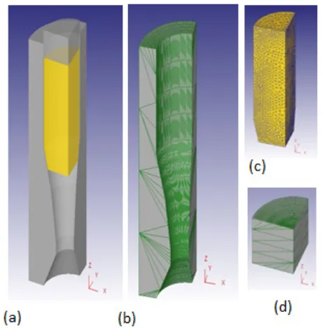
analyze bulk plastic deformation, and is especially suited for the present analysis. It takes advantage of the fact that plastic deformation is usually highly localized. The present analyses adopt the following assumptions: (1) both the container and the die are rigid bodies, (2) the extrusion billet is a rigid-plastic material, (3) the important parameters which effect on the extrusion process were assumed to be: the reduction of area is constant (R.A. = 0.75), semi- cone die angles (α = (5o, 6o, 7o, 10o, 12o, and 14o)) coefficient of frictions (μ = 0.05) and the extrusion speed is (V = 250 mm/s). According to symmetry quarter model was considered, tetrahedral element type with 5980 number of element and 17940 nodes were chosen in simulating the aluminum rod. Since the present study concentrate on the stress distribution on the extruded bar, a rigid die and punch was considered to ignore any deformation in the die and punch. Figure (2) shows the die-punch setup and the 3D finite element model.
Figure 2. Quarter metal of (a) punch, die, and billet arrangement, (b)
Bottom die, (c) Workpiece, (d) Top die (punch)
2.1. Applying the Boundary Conditions
After building the model, the following step was to apply velocity to the structure in preparation for solution. In order to properly model structures behavior, it is necessary to apply velocity with respect to a specified time interval. Unlike most implicit analysis, all resulting stress is an explicit analysis and must be time- dependent in nature. The following are the parts and the boundary conditions applied to the die and extrusion part respectively:
(i). The Die Part
[image:2.595.65.284.467.647.2](ii). The Extrusion Part
Since the extrusion part is plastic this is the only part that suffers deformation during the extrusion process. The boundary conditions are: zero velocity in the x and y directions and 250 mm/sec. on the z-direction.
2.2. Material Type and Properties
[image:3.595.57.300.256.532.2]Aluminum-1100 billet with diameter 10mm was chosen to be extruded to final rod diameter of 5 mm with extrusion ratio of 0.75. The chemical composition of Al-1100 is shown in Table (1), while the important physical and mechanical properties are shown in Table (2).
Table 1. Chemical Composition of Al-1100 [12]
Element % Element %
Al 99.6 Mn 0.03
Cu 0.05 Si 0.25
Fe 0.35 Ti 0.03
Mg 0.03 Zi 0.05
V 0.05
Table 2. Physical and Mechanical Properties of Al-1100 [13]
Property Value
Density 2.71 gm/cm3
Brinell Hardness 23
Ultimate Tensile Strength 89.6 Mpa
Tensile Yield Strength 34.5 Mpa
Elongation at Break 35.00% @ Thickness 1.59 mm 45.00% @ Diameter 12.7 mm
Modulus of Elasticity 68.9 Gpa
Poisson's Ratio 0.33
Shear Modulus 26 Gpa
Shear Strength 62.1 Mpa
3. Design and Training of ANN Model
for Stresses Prediction
Artificial Neural Networks are based on the basic model of the human brain with capability of generalization and learning. The term "artificial" means that neural nets are implemented in computer programs that are able to handle the large number of necessary calculations during the learning process.
Artificial neural networks (ANN) are a large class of parallel processing architectures, which can mimic complex and nonlinear relationships through the application of many nonlinear processing units called neurons. The relationship can be ‘learned’ by a neural network through adequate training from the experimental data. It can not only make decisions based on incomplete and disorderly information, but can also generalize rules from those cases on which it
was trained and apply these rules to new cases. Usually, the structure of an ANN is hierarchical with neurons grouped in different layers designed as an input layer, hidden layers and on output layer, as shown in Fig. 3. Signals are supplied to the neurons of the input layer; each neuron of this layer then generates an output signal, which is transferred to the neurons of the hidden layer. The output signals are generated by the last layer (output layer).
In this work, the inputs of the model are time step and die angle. The outputs are stress distribution along the x, y, and z-axis and effective stress respectively at different die angles, which each stress have one program.
[image:3.595.316.552.340.472.2]In this study, artificial neural networks ANN with 2–25 neurons was trained; it was found that ANN with 8 neurons for x-stress, 6 neurons for y-stress, 8 neurons for z-stress, and 5 neurons for effective stress in one hidden layer gives a minimum RMS error and maximum correlation coefficient (R). In the first step, training act was performed for adjusting connection weights between input layer to hidden layer and between hidden layer and output layer until the network to produce outputs that are close enough to the desired outputs.
Figure 3. Schematic structure of back propagation neural network
4. Genetic Algorith
m Model
The genetic algorithm is a method for solving both constrained and unconstrained optimization problems that is based on natural selection, the process that drives biological evolution. The genetic algorithm repeatedly modifies a population of individual solutions. At each step, the genetic algorithm selects individuals at random from the current population to be parents and uses them to produce the children for the next generation. Over successive generations, the population "evolves" toward an optimal solution. Genetic algorithm can be used to solve a variety of optimization problems that are not well suited for standard optimization algorithms, including problems in which the objective function is discontinuous, non-differentiable, stochastic, or highly nonlinear.
to find an optimal value [14]. A genetic algorithm mimics the natural selection process by which a superior creature evolves whilst inferior creatures fade out from their population as generations go by. In an analogy to the present design problem, a superior creature is a set of strings or a set of design variables that can lead to minimization of the objective function [2].
5. Result and Discussion
5.1 Comparison of Extrusion Force with other Works
The extrusion force is validated by comparing some results of this present work with previous studies. Figure (4) shows a Comparison with the present finite element results, this result compared with the experimental work of Gouveia et al. [15] for the same conditions (initial diameter and initial height equal to 15 and 45 mm, a constant punch velocity of 4.3 mm/s, semi-cone die angle is 300 and reduction in area is 60% were used in the experimental investigation) to validate the present work and the maximum error was 9.42% between the present work and experimental work for Gouveia et al. They were a good agreement.
5.2 Finite Element Results
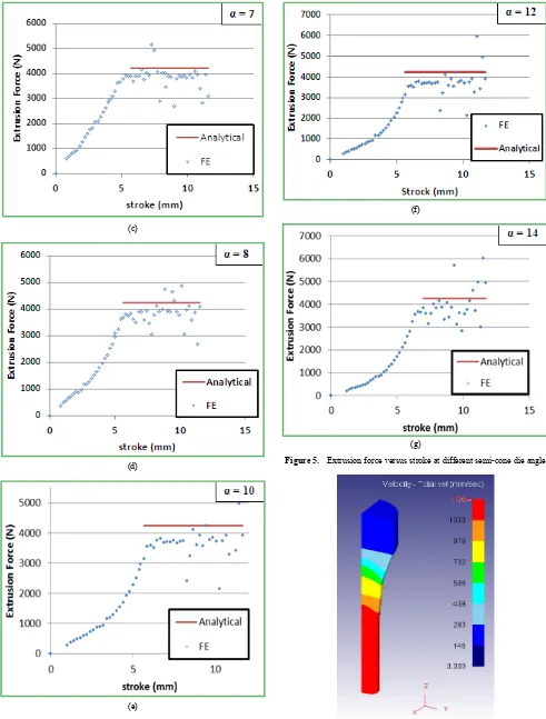
Type of metal flow and stress distribution in metal extrusion process is a highly complex for the complicated die design. Therefore finding the optimum die angle is most important task in extrusion process. The effect of the die semi-angle on the extrusion force for an extrusion process performed under conditions Do=10 mm, Df =5 mm, R.A. = 75%, and μ=0.05. It is seen that the extrusion force initially increases monotonously until the die is completely filled by the billet. It can be seen that the extrusion force increases as the semi-angle is increased but there is an optimum angle in these conduction. Extrusion force can be estimated analytical shown in equation (1) and (2) [16].
𝑃𝑃𝑒𝑒𝑒𝑒 = 𝑌𝑌 � 1+𝐵𝐵𝐵𝐵 � �1 − � 𝑅𝑅𝑅𝑅12 � 2𝐵𝐵
� (1) F = 𝑃𝑃𝑒𝑒𝑒𝑒* 𝐴𝐴𝑜𝑜 (2) Where 𝑃𝑃𝑒𝑒𝑒𝑒is the extrusion punch pressure, Y is the yield strength of material, F is the extrusion force, 𝐴𝐴𝑜𝑜 is the billet area, 𝑅𝑅1 = radius before extrusion, 𝑅𝑅2 = radius after extrusion, B = µcot α, µ is the friction coefficient, α is the semi-cone die angle.
Figure (5) shows the extrusion force against stroke diagram for different semi-cone die angle. Results from the finite elements also compared with the analytical results derived from equations (1) and (2). It can note that there is a convergence between the analytical results with that of the finite element model.
Figure 4. Comparison of extrusion force with Gouveia et al. model [15].
(a)
[image:4.595.314.551.78.281.2] [image:4.595.310.551.302.709.2](c)
(d)
(e)
(f)
[image:5.595.58.549.78.725.2](g)
Figure 5. Extrusion force versus stroke at different semi-cone die angle
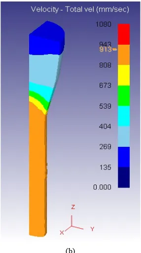
(b)
Figure 6. Flow exit velocity distribution for various semi-cone die angle
during extrusion process (a) α = 5o and (b) α = 14o
Figure (6) illustrates the flow velocity distributions in billets extruded through dies with two different semi-angles under the same extrusion conditions. It can be seen that the flow velocity decreases as the semi-angle increases. Specifically, the flow velocity reduces from 1030 mm/s to 913 mm/s as the semi-angle increases over the range 5◦ ≤ α
≤14◦.
5.3. Neural Network Results
In present study, two type of stresses affected the work piece are taken into account the normal stresses along the x, y, and z-axis and effective stress at different die angles. These stresses were collected from the finite element results and then data were randomly divided into two partitions: training, and testing data. The testing data was used for estimating the performance of the trained network on new data, which never was seen by the network during the training.
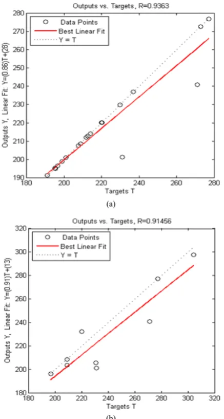
[image:6.595.106.249.78.333.2]Table 3 shows the performance of neural network predictions and mean square error for both the training and testing data. Meanwhile, the comparisons between the FAM results and corresponding predicted results for both the training and testing datasets of Al-1100 are shown in Figure (7, 8, 9 and 10). The trendline involved in Figure (7, 8, 9 and 10) indicates close agreement between the predicted and FAM results stresses. The results show that a very good correlation between FAM results and predicted results has been obtained, which suggests that the neural network is able to predict the compressive deformation behaviors of Al-1100 successfully.
Table 3. Statistical analysis of the performance of ANN model for training
and testing predictions
Stresses Correlation Coefficient (R) Mean Square Error (MSE)
Training Testing Training Testing
X axis 0.9363 0.9145 0.0644 0.0371
Y axis 0.9768 0.9396 0.0769 0.0019
Z axis 0.9955 0.9503 0.0597 0.0128
Effective 0.9045 0.9170 0.0461 0.0028
(a)
[image:6.595.316.551.96.674.2](b)
Figure 7. Comparisons between predicted effective stresses: (a) Training
(a)
[image:7.595.69.288.78.486.2](b)
Figure 8. Comparisons between predicted X-axis stress: (a) Training data
(b) Testing data
(a)
[image:7.595.327.536.79.278.2](b)
Figure 9. Comparisons between predicted Y-axis stress: (a) Training data
(b) Testing data.
(a)
(b)
Figure 10. Comparisons between predicted Z-axis stress: (a) Training data
[image:7.595.325.539.313.721.2]5.4. Genetic Algorithm Results
5.4.1. Single–objective optimization of extrusion process
Minimum Effective stress; in this investigation, a genetic algorithm with a single point crossover has been used. Each individual was constructed with a fitness function, which was obtained from ANN model. The initial population was chosen to be 20 and Crossover Fraction was chosen to be 0.8.
The optimum values of process parameters and the best possible of effective, X-axis, Y-axis and Z-axis stresses which is show in the table (4). From this table it can be seen that the effective stress is 123.38 MPa, X-axis stress is 215.918 MPa, Y-axis stress is 245.52 MPa and Z-axis stress is 250.26 MPa which can be resulted when step time is 0.0266 sec and extrusion die angle is 12.2o.
Minimum X-stress; similarly in the case of effective stress, the genetic algorithm was Population size and crossover fraction are 20 and 0.75 of GA parameters were found to be able to optimize the process parameters. From table (4) it is clear that the optimal X-axis stress 161.03 MPa, effective stress is 120.84 MPa, Y-axis stress is 148.26 MPa and Z-axis stress is 180.41 MPa which can be resulted when
step time is 0.0235 sec and extrusion die angle is 13.8o. Minimum y-stress; population size and crossover fraction is 20 and 0.80 of GA parameters were found to be able to optimize the process parameters, respectively. From table (4), it is evident that the optimal Y-axis stress is 195.6 MPa, effective stress is 122.07 MPa, X-axis stress is 187.74 MPa and Z-axis stress is 214.41 MPa which can be resulted when step time is 0.0285 sec and extrusion die angle is 12.4o.
Minimum z-stress; population size and crossover fraction is 20 and 0.8 of GA parameters were found to be able to optimize the process parameters, respectively. From table (4), it is evident that the optimal Z-axis stress is 109.11 MPa, effective stress is 118.25 MPa, X-axis stress is 105.01 MPa and Y-axis stress is 48.98 MPa which can be resulted when step time is 0.0368 sec and extrusion die angle is 12.5o. 5.4.2. Multi –objective optimization of extrusion process
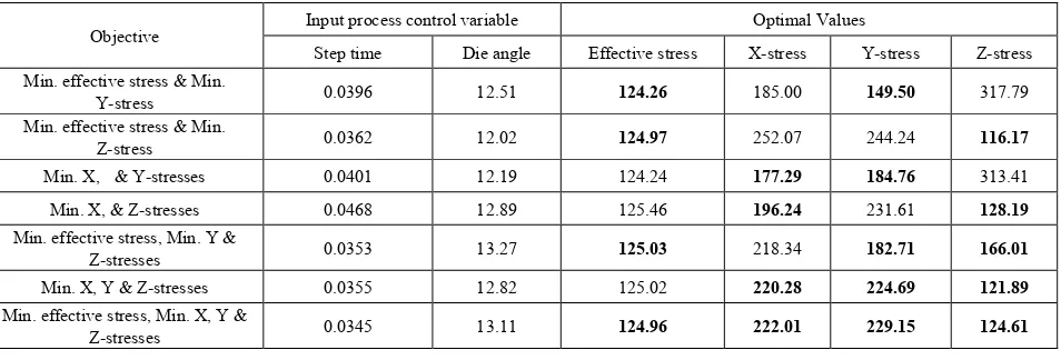
[image:8.595.66.549.378.470.2]Multi objective genetic algorithm in MATLAB toolbox is used to get more than one optimum value of welded plate's strength. Table (5) shows results of best set of solutions for multi objective genetic algorithm. It can be seen that when want to obtain value of angle.
Table 4. The optimum values of extrusion process parameters and the optimal values of stress for single objective function.
objective Input process control variable Optimal Values
Step time Die angle Effective stress X-stress Y-stress Z-stress
Min. effective stress 0.0266 12.2 123.38 215.918 245.52 250.26
Min. X-stress 0.0235 13.8 120.84 161.03 148.26 180.41
Min. Y-stress 0.0285 12.4 122.07 187.74 195.60 214.41
[image:8.595.70.547.495.657.2]Min. Z-stress 0.0368 12.5 118.25 105.01 48.98 109.11
Table 5. The optimum values of the extrusion process parameters and the best optimal values of stresses for multi objective function.
Objective Input process control variable Optimal Values
Step time Die angle Effective stress X-stress Y-stress Z-stress
Min. effective stress & Min.
Y-stress 0.0396 12.51 124.26 185.00 149.50 317.79
Min. effective stress & Min.
Z-stress 0.0362 12.02 124.97 252.07 244.24 116.17
Min. X, & Y-stresses 0.0401 12.19 124.24 177.29 184.76 313.41
Min. X, & Z-stresses 0.0468 12.89 125.46 196.24 231.61 128.19
Min. effective stress, Min. Y &
Z-stresses 0.0353 13.27 125.03 218.34 182.71 166.01
Min. X, Y & Z-stresses 0.0355 12.82 125.02 220.28 224.69 121.89
Min. effective stress, Min. X, Y &
6. Conclusions
1. The finite element model was successfully simulated the stress distribution in the direct rod extrusion of Al-1100. Also this study demonstrated that optimum die angle reduce the magnitude of effective stresses, stresses x, y, and z.
2. ANN model with three layers and one hidden layer 8 neurons for x-stress, 6 neurons for y-stress, 8 neurons for z-stress, and 5 neurons for effective stress in one hidden layer gives a minimum RMS error and maximum correlation coefficient (R) is a useful method for the prediction of stresses where the die angle and step time are input parameters and there is a close agreement between the predicted and FAM results stresses.
3. Combine of genetic algorithm and ANN model was used for optimization the stresses in Al-1100 in cold compression.
4. The results show that the optimal angle between 12o and 14o because the stresses at these angle less when compared with other angle.
REFERENCES
[1] HE You-feng, XIE Shui-sheng, CHENG Lei, HUANG Guo-jie, FU Yao. FEM simulation of aluminum extrusion process in porthole die with pockets. Trans. Nonferrous Met. Soc. China, vol. 20, pp.1067-1071, 2010.
[2] J.S. Chung, S.M. Hwang. Application of a genetic algorithm to the optimal design of the die shape in extrusion. Journal of Materials Processing Technology, vol. 72; pp.69–77, 1997. [3] Jayaseelan.V, Kalaichelvan.K, Vijay ananth.S. Lubrication
Effect on Friction Factor of AA6063 in Forward Extrusion Process. Procedia Engineering, vol. 97, pp. 166 – 171, 2014. [4] A.R. Eivani, A. Karimi Taheri. The effect of dead metal zone
formation on strain and extrusion force during equal channel angular extrusion. Computational Materials Science, vol. 42, pp. 14–20, 2008.
[5] L. Donati, L. Tomesani. The effect of die design on the production and seam weld quality of extruded aluminum profiles. Journal of Materials Processing Technology, vol. 164–165, pp. 1025–1031, 2005.
[6] J.S. Ajiboye, M.B. Adeyemi. Effects of die land on the cold extrusion of lead alloy. Journal of Materials Processing Technology, vol. 171, pp. 428–436, 2006.
[7] K. Kuzman, E. Pfeifer, N.Bay, J.Hunging. control of material flow in a backward can- forward rod extrusion. Journal of materials Processing Technology, vol. 60, pp. 141-147, 1996. [8] D.Y. Yang, K.J. Kim. Design of processes and products
through simulation of three-dimensional extrusion. Journal of Materials Processing Technology, vol.191, pp. 2–6, 2007. [9] Serope Kalpakjian, teven R.Schmid. Manufacturing processes
for engineering material. 5th edition, 2008.
[10]Hao Nanhai, Li Kezhi. Numerical design of the die land for shape extrusion. Journal of Materials Processing Technology, vol. 101, pp. 81-84, 2008.
[11]T. Chanda, J. Zhou, J. Duszczyk. FEM analysis of aluminium extrusion through square and round dies. Materials and Design, vol. 21, pp. 323-335, 2000.
[12]P. Tiernan, M.T. Hillery, B. Draganescu and M. Gheorghe. Modelling of cold extrusion with experimental verification. Journal of Materials Processing Technology, vol. 168, pp. 360–366, 2005.
[13]Serope Kalpakjian, Steven R.Scmid, Chi-Wah Kok. Manufacturing process for engineering materials. 5𝑡𝑡ℎedition, Prentice Hall, 2008.
[14]Marziyeh Ramzi, Mahdi Kashaninejad, Fakhreddin Salehi, Ali Reza Sadeghi Mahoonak, Seyed Mohammad AliRazavi. Modeling of rheological behavior of honey using genetic algorithm–artificial neural network and adaptive neuro-fuzzy inference system. Food Bioscience, vol. 9, pp. 60-67, 2015. [15]B.P.P.A. Gouveia, J.M.C. Rodrigues and P.A.F. Martins,
Finite element modelling of cold forward extrusion using updated Lagrangian and combined Eulerian–Lagrangian formulations. Journal of Materials Processing Technology, vol. 80–81, pp. 647–652, 1998
![Table 1. Chemical Composition of Al-1100 [12]](https://thumb-us.123doks.com/thumbv2/123dok_us/8758714.893468/3.595.57.300.256.532/table-chemical-composition-al.webp)
![Figure 4. Comparison of extrusion force with Gouveia et al. model [15].](https://thumb-us.123doks.com/thumbv2/123dok_us/8758714.893468/4.595.310.551.302.709/figure-comparison-extrusion-force-gouveia-et-al-model.webp)