N A N O E X P R E S S
Open Access
Optimization of the dye-sensitized solar cell
performance by mechanical compression
Teen Hang Meen
1, Jenn Kai Tsai
1*, Yu Shin Tu
1, Tian Chiuan Wu
1, Wen Dung Hsu
2and Shoou-Jinn Chang
3Abstract
In this study, the P25 titanium dioxide (TiO2) nanoparticle (NP) thin film was coated on the fluorine-doped tin oxide (FTO) glass substrate by a doctor blade method. The film then compressed mechanically to be the photoanode of dye-sensitized solar cells (DSSCs). Various compression pressures on TiO2NP film were tested to optimize the performance of DSSCs. The mechanical compression reduces TiO2inter-particle distance improving the electron transport efficiency. The UV–vis spectrophotometer and electrochemical impedance spectroscopy (EIS) were employed to quantify the light-harvesting efficiency and the charge transport impedance at various interfaces in DSSC, respectively. The incident photon-to-current conversion efficiency was also monitored. The results show that when the DSSC fabricated by the TiO2NP thin film compressed at pressure of 279 kg/cm
2
, the minimum resistance of 9.38Ωat dye/TiO2NP/electrolyte interfaces, the maximum short-circuit photocurrent density of 15.11 mA/cm2, and the photoelectric conversion efficiency of 5.94% were observed. Compared to the DSSC fabricated by the non-compression of TiO2NP thin film, the overall conversion efficiency is improved over 19.5%. The study proves that under suitable compression pressure the performance of DSSC can be optimized.
Keywords:Mechanical compression; Dye-sensitized solar cells (DSSCs); TiO2; Doctor blade method; Conversion efficiency
Background
In recent years, most of the solar cells are fabricated on Si-based substrate [1] which is flat and rigid; however, several good substitutes have been discovered to replace Si-based substrates for applications in flexible solar panels. Dye-sensitized solar cell (DSSC) is one of alternatives as it can be built on flexible substrate with low cost and light weight [2-4]. Grätzel and his colleagues published the first DSSC in 1992 [2]. They adopted nanoporous ti-tanium dioxide (TiO2) as photoanode, metal ruthenium
(Ru) organic complexes as dyes, and I2/I3−redox couple as
electrolyte. The photoelectric conversion efficiency for the first DSSC is 7.1%. Since then, improving the performance of dye-sensitized solar cell has been the primary goal of researchers.
Dye-sensitized solar cell has three main components: (i) the dye which absorbs solar energy to generate excitons [5,6], (ii) the nanostructured metal oxide (photoanode)
which captures electrons from the dye [7,8], and (iii) the redox electrolyte which transports electrons and holes from metal oxide and oxidized dye to electrodes [9,10]. Therefore, the conversion efficiency of dye-sensitized solar cell is mainly influenced by transparent conductive oxide (TCO) (photoanode), sensitizer (dye), electrolyte, electrodes, etc.
The photoanode is usually made by TiO2nanoparticles
due to its chemical stability, non-toxicity, relatively high transmittance in the visible spectral, etc. It has been pro-ven a good photoelectric material. The band gaps of rutile- and anatase-phased TiO2are 3.0 and 3.2 eV,
re-spectively. The anatase phase is more preferred to be used in the DSSC owing to its photocatalytic property and wide direct band gap [11].
Literatures have shown that the thickness of TiO2
nanoparticle (NP) thin film plays an important role on the conversion efficiency of DSSC. However, using nano-particles as a carrier for dye molecules to absorb light hinders the electron transport to anode electrode, due to the loss of electrons by either recombination between electrons and the oxidized dye molecules or
electron-* Correspondence:[email protected]
1
Department of Electronic Engineering, National Formosa University, Yunlin 632, Taiwan
Full list of author information is available at the end of the article
accepting species in the electrolyte or back reaction dur-ing the transport processes [12-14].
Mechanical compression of TiO2 NP thin film to
re-duce the film thickness could be an effective method to suppress the recombination without changing the mass and effective surface area of TiO2NPs. The reduction of
the thickness helps reducing the electron transport path and internal impedance [15,16]. Schematic diagram of compression effect is shown in Figure 1.
Previously, we have reported that the performance of TiO2NP thin films can be improved by mechanical
com-pression, but the compression pressure was not optimized [12]. In this study, the effect of compression pressure on the TiO2 NP thin films was studied in detail. The
structures and morphologies of TiO2NP thin films were
characterized using field-emission scanning electron mi-croscope (FE-SEM). The UV–vis spectrophotometer and electrochemical impedance spectroscopy (EIS) were em-ployed to quantify the light-harvesting efficiency and the charge transport impedance at various interfaces in DSSC, respectively. The incident photon-to-current con-version efficiency was also monitored. The I-V characte-rization was performed under standard air mass 1.5 global (AM 1.5 G) simulated sunlight.
Methods
Experimental details
Deposition of TiO2thin films as photoanode
TiO2paste of 10 wt% was prepared by mixing
nanocrys-talline TiO2particles (TG-P25, Degussa, Shinjuku, Tokyo,
Japan; the average nanoparticle diameter was about 25 to 30 nm) withtert-butyl alcohol and deionized water. TiO2
paste was scraped on a transparent fluorine-doped-tin oxide (FTO) glass with resistivity of 8Ω/sq by the doctor blade method to form TiO2 NP thin film. Subsequently,
the mechanical compression was performed on the film. The TiO2NP thin film then was annealed in two steps in
air: under 150°C for 90 min and then under 500°C for 30 min. The 150°C annealing was set for decomposition of residual organic compounds, and the 500°C annealing was used to assist the interconnection of TiO2 NPs,
so that the loss of electrons during transport becomes less. In this study, various pressures, 61, 131, 279, 558, and 858 kg/cm2, were adopted to compress the TiO2NP thin
film, named samples B to F, respectively. The as-deposited film, sample A, was used as a control group.
DSSC fabrication
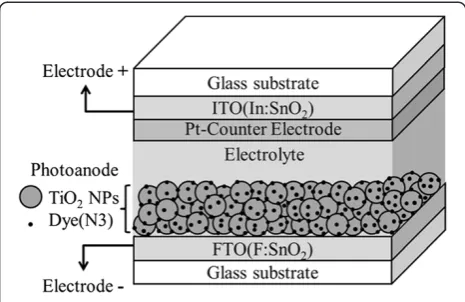
A schematic diagram of dye-sensitized solar cell with/ without compressed TiO2NP thin film as photoanode is
shown in Figure 2. The FTO substrate coated with TiO2
NP thin film were immersed in 0.3 mM N3 dye (cis-bis (dithiocyanato)-bis(4,4′-dicarboxylic acid-2,2′-bipyridine) ruthenium (II)) solution for 2 h to fabricate working elec-trode. Subsequently, the electrode was rinsed in aceto-nitrile for a few seconds to wash out unbound dyes and dried in the oven at 45°C. The counter electrode was fab-ricated by a grown 1-nm thick Pt thin film on indium tin oxide (ITO) glass with electroplating method. The wor-king electrode then bonded to a counter electrode by a 50-μm thick hot-melt polymer spacer. Sealing was ac-complished by pressing the two electrodes together at 115°C for a few seconds. The redox electrolyte, consisting of 0.5 M LiI, 0.05 M I2, and 0.5 M 4-tert-butylpyridine
(TBP), and 1 M 1-propy1-2,3-dimethylimidazolium (DMPII) mixed with 3-methoxypropionitrile (MPN), was injected into the cell by capillary force through an injecting hole previously mechanically drilled on the counter electrode. Finally, the hole was covered and sealed with a piece of hot-melt polymer to prevent the leakage of fluid-type electrolyte. The resulting active electrode area was approximately 0.25 cm2(0.5 × 0.5 cm).
Characterizations and photoelectrochemical measurement
The structures and morphologies of TiO2NP thin films
were measured using the field-emission scanning electron microscope (FE-SEM; JSM-7500 F, JEOL, Akishima-shi, Japan). Porosity of TiO2NPs was analyzed by ImageJ
[image:2.595.58.539.634.716.2]pro-gram from FE-SEM images [17]. The propro-gram is a public domain Java image processing program from the National Institute of Mental Health (NIMH), Bethesda, MD, USA. The ultraviolet–visible (UV–vis) transmittance spectrum was observed by a UV–vis spectrophotometer (U-2900, Hitachi High-Technologies Corporation, Tokyo, Japan) with the wavelength from 300 to 800 nm at room tem-perature. Electrochemical impedance spectroscopy (EIS; Zahner Zennium, Kronach, Germany) measures the cur-rent response while applying an AC voltage as a function
of frequency. The frequency ranged from 10 mHz to 100 kHz under illumination of AM 1.5 G at biased open-circuit voltage. The incident photon-to-current con-version efficiency (IPCE) that used to determine the light-harvesting efficiency of the dye, the quantum yield of electron injection, and the efficiency of collecting the injected electrons was recorded using an IPCE instru-ment equipped with a 1000-W Xenon arc lamp as the light source that composed of a compact 1/8 meter monochro-mator (CM110, Spectral Products, Putnam, CT, USA), a color filter wheel (CFW-1-8, Finger Lakes Instrumentation, Lima, NY, USA), and a calibrated photodiode (FDS1010-CAL, Thorlabs Inc., Newton, NJ, USA). The IPCE data were taken by illuminating monochromatic light on the solar cells (with the wavelength from 300 to 800 nm) and performed with a source meter (2400, Keithley Instruments, Inc., Cleveland, OH, USA). The current– voltage characteristics were measured by Keithley 2400 (Keithley Instruments, Inc., Cleveland, OH, USA) source meter under a simulated sunlight (SAN-EI XES-40S1, San Ei Brand, Higashi-Yodogawa, Japan), AM 1.5 G radiation at 100 mW/cm2.
Results and discussion
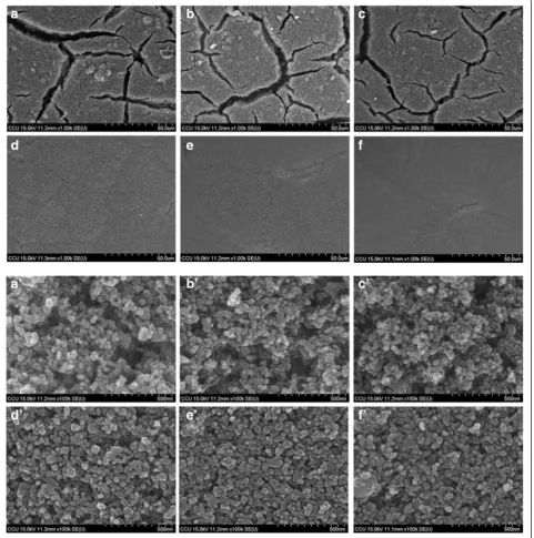
Figure 3 shows the FE-SEM image of TiO2NP thin films
with and without mechanical compression. Figure 3a shows the surface morphology of the as-deposited TiO2
NP (sample A) thin film. There are large cracks observed. Several mechanisms have been proposed to explain the crack formation, such as capillary force that appears when solvent rapidly evaporate from film surface during drying process, decreasing of bond strength among TiO2 NPs
when the film is thick, and large mismatch of thermal ex-pansion coefficient between the FTO substrate and TiO2
NP thin film [18,19]. Figure 3b,c,d,e,f shows the sur-face morphology of TiO2 NP thin film after
mechani-cal compression at 61, 131, 279, 558, and 838 kg/cm2
(samples B-F), respectively. As the compression pressure increases, the surface becomes smooth. The surface crack is almost not observed while the compression pressure is 279 kg/cm2, as shown in Figure 3d. The film become completely uniform and crack-free when the compression pressure is above 558 kg/cm2, as shown in Figure 3e,f. Figure 3a’,b’,c’,d’,f’, which shows the magnification images, demonstrates that the distance between TiO2NPs is
grad-ually decreasing when the compression pressure increases. There, however, are still enough spaces between TiO2
nanoparticles for the dye molecules to adhere and electro-lyte to permeate.
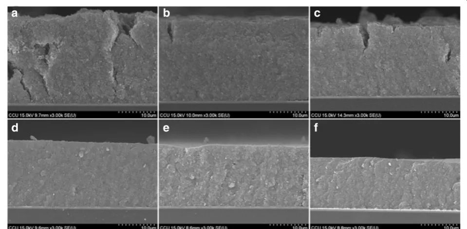
Figure 4 shows the cross-section images of TiO2NP
thin film after compression with different pressures. Figure 4a shows the crack of as-deposited TiO2NP thin
film (sample A) that penetrates from the film surface to the FTO substrate. The cracks are gradually mitigated when the compression pressure increases as shown in Figure 4b,c,d,f. When the compression pressure reaches 279 kg/cm2(Figure 4d), there are no obvious cracks ob-served. The results indicate that post compression is an effective method to synthesis crack-free TiO2 NP thin
film. The thickness of the TiO2 NP thin film also
re-duces as the compression pressure increases. The thick-nesses are 24.0, 23.6, 20.2, 18.4, 17.2, and 14.4μm when the compression pressures are 0, 61, 131, 279, 558, and 858 kg/cm2, respectively. Therefore, the distance be-tween TiO2 nanoparticles is short for condensed films.
It is then expected that the transport path of the elec-trons also becomes short, which making them easier to research anode electrode [18].
Figure 5 shows the FE-SEM images from Figure 3 (a’,b’,c’,d’,e’,f’) after being analyzed by the ImageJ program in order to quantify the porosity of TiO2 NP thin film.
The black area represents the unfilled space, and the white area represents the TiO2NPs. The images show that the
black area decreases as the compression pressure in-creases. Figure 6 shows both the thickness and porosity of TiO2NP thin film as a function of the compression
pres-sure. The thickness and porosity of TiO2 NP thin films
decrease from 24.0 to 14.4 μm and 35.56 to 14.85%, re-spectively, as the compression pressure increases from 0 to 858 kg/cm2. The result indicates that the compression treatment not only reduces the thickness but also de-creases the porosity to have small inter-particle distance.
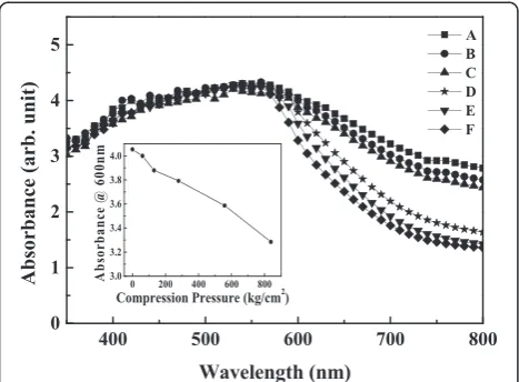
[image:3.595.57.290.89.240.2]Figure 7 shows the UV–vis absorption spectra of sam-ples A to F with dye absorption. The absorbance is offset to that of air so that the absorbance of air was set to be zero. At the wavelength shorter than 560 nm, the absor-bances are almost the same for all the samples, however, at the wavelength longer than 560 nm, the absorbance de-creases as the post-compression pressure inde-creases. Inset of Figure 7 shows the decrease of absorbance at wave-length of 600 nm as the compression pressure increases.
Figure 2The schematic diagram of dye-sensitized solar cell with/without compressed TiO2nanoparticle thin film as
The absorbance is due to light absorption by the N3 dye molecules that adhere on the TiO2 NP surface. The
same absorbance of all the samples at the wavelength less than 560 nm indicates that the number of dye mole-cules on the TiO2NP surface is almost the same for all
the samples even though they have been treated with different compression pressures. Hence, the mechanical compression treatment reduces the inter-particle spa-ces, and the dye molecules are still allowed to permeate
through the TiO2NPs and adhere on their surface. The
decrease of absorbance for high-pressure compressed samples at the wavelength longer than 560 nm is attrib-uted to high light-transmission rate for TiO2 NP thin
[image:4.595.59.541.92.578.2]film. The samples without being compressed with high pressure also show cracks (Figures 3a,b,c and 4a,b,c), which enhance light scattering resulting increase of light traveling distance in the film and promoting light absorbance.
Figure 3FE-SEM micrographs for TiO2nanoparticles film on FTO glass fabricated by doctor blading method with/without compression
Figure 8 shows the electrochemical impedance spec-troscopy (Nyquist plot) of samples A to F after fully fa-bricated as dye-sensitized solar cells. The Nyquist plot demonstrates the minus imaginary part of impedance (−Z″) as a function of the real part of the impedance (Z′),
[image:5.595.58.538.92.328.2]while the measured frequency swept from 10 mHz to 100 kHz. The method is very useful to understand the role of interfaces during electron transport. Three distinct se-micircles are observed, which are attributed to the electro-chemical reaction at the Pt counter electrode/electrolyte
Figure 4Cross-sectional images of FE-SEM of TiO2nanoparticles film with and without compression treatment. (a)As-deposited film
[image:5.595.60.537.466.702.2]and(b-f)after mechanical compression at various pressures, 61, 131, 279, 558, and 858 kg/cm2with the thickness of 24.0, 23.6, 20.2, 18.4, 17.2, and 14.4μm, respectively.
Figure 5FE-SEM images analyzed by the ImageJ program.The black area means the unfilled space, and the white area means the TiO2NPs.
interface, charge transport through the dye/TiO2 NP/
electrolyte interfaces, and the Warburg diffusion process of I−/I3−in the electrolyte from left to right. The values of
the electrochemical impedance for samples A to F are listed in Table 1. The diameter of the first (left-most) semicircle refers to the resistance (RPt) at the Pt counter electrode/electrolyte interface. The values are almost the same for all the samples indicating that the fabrication conditions are consistent. The diameter of the second (middle) semicircle corresponds to the resistance (RK) as-sociated with transport of electrons through dye/TiO2
NP/electrolyte interfaces. The value is minimum for sam-ple D, indicating that the recombination probability be-tween electrons and the iodides of the electrolyte is lowest in this case [20]. The diameter of the third (right-most) semicircle (RD) represents the impedance of the I3− ion
diffusion in the electrolyte. Since the diffusion of I3− ions
is suppressed as the electrolyte is confined between two very close TiO2 nanoparticles, the condensed TiO2 NP
thin film would have largeRD. On the other hand, thick TiO2NP thin film would increase the distance for I3−ions
to diffuse to counter electrode and it hence would also have largeRD. Therefore,RDof samples C and D are smal-lest and RD of samples A and F are largest, as sample A has the thickest TiO2NP thin film and sample F has the
highest density of TiO2NPs in this study.
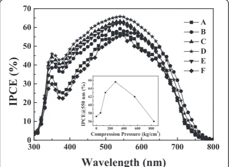
Figure 9 shows the incident monochromatic photon-to-current conversion efficiency as a function of photon wavelength ranging from 300 to 800 nm. Sample D has the maximum IPCE among all the samples. In general, the photocurrent depends on the number of photo-excited electrons which is related with the absorption capacity of dye molecules, the recombination rate be-tween electrons and oxidized dye molecules, and the redox series in the electrolyte. Increase of light traveling distance in photoanode thin film would improve effi-ciency of photo excitation; however, thick photoanode thin film would also enhance the recombination rate. Thus, to have high IPCE compromise among the increase of optical absorption, the reduction of recombination rate and the improvement of effective carrier transport are ne-cessary. For example, sample A possesses the best absorp-tion spectra among all the samples but its IPCE is not the highest one. The result indicates that the photo-excited electrons generated after the absorption of incident light by dye molecules cannot effectively transport to anode electrode due to high recombination rate and long passing distance (thick TiO2NP thin film) that cause highRKand
[image:6.595.305.538.88.257.2]RDobserved in Figure 8. The inset of Figure 9 shows the IPCE at wavelength of 550 nm as a function of the
Figure 6Thickness and porosity of TiO2NP thin films as a
[image:6.595.56.292.90.243.2]function of the compression pressure.
Figure 7UV–vis absorption spectra of TiO2nanoparticle thin
[image:6.595.57.291.512.684.2]film with and without compression treatment.Curve A is the as-deposited film, and curves B to F are the after mechanical compression at various pressures, 61, 131, 279, 558, and 858 kg/cm2.
Figure 8Nyquist plots of DSSCs made by TiO2nanoparticle
compression pressure. The IPCE of sample D is 8% larger than that of sample A.
Figure 10 shows the results of the photocurrent-voltage characteristics of samples A to F under AM 1.5 G simu-lated sunlight. The photovoltaic properties of DSSCs are also summarized in Table 1. The open circuit voltage (VOC) and Fill factor of each sample is almost the same, indicating that the mechanical compression only changes the inter-particle distance. Sample D, whose TiO2NP thin
film was compressed with the pressure of 279 kg/cm2, has the highest short circuit current density (JSC) of 15.11 mA/cm2 and the photoelectric conversion effi-ciency (η) of 5.94%. In contrast, sample A, whose TiO2NP
thin film did not treat with any mechanical compression, has the highest absorbance but has the lowest short circuit current density (JSC) of 10.36 mA/cm2and has only 4.97% photoelectric conversion efficiency (η). The result indi-cates that tuning inter-particle distance by compression of TiO2NP thin films is an effective method to improve the
performance of DSSCs. There exist an optimal
inter-particle distance so that the IPCE and current density is maximized. Thus, obtaining optimal inter-particle dis-tance of TiO2 nanoparticles is essential to fabricate high
performance DSSCs.
Conclusions
In this study, the compression of TiO2NP thin film was
tested to investigate the effect of film density. The results indicate that the performance of DSSC is compromised among the increase of optical absorption, the reduction of recombination rate, and the improvement of effective car-rier transport. Therefore, the distance between TiO2NPs
is essential to tune the performance of DSSCs. The dis-tance can be characterized by the porosity of TiO2NPs
films as analyzed by the ImageJ program. The results dem-onstrate that as the compression pressure increases the porosity decreases hence close-packing TiO2 NPs. The
DSSC fabricated by the TiO2NP thin film compressed at
[image:7.595.58.539.112.209.2]the pressure of 279 kg/cm2has the smallest charge trans-port resistance at the TiO2/dye/electrolyte interface, the Table 1 Characteristics of DSSCs using TiO2nanoparticle thin film on the FTO glass fabricated by doctor blading method with and without compression treatment
Samples Pressures (kg/cm2)
VOC(V) JSC(mA/cm2) F.F (%) η(%) RPt(Ω) RK(Ω) RD(Ω)
A None 0.72 10.36 54.36 4.97 4.16 12.05 9.7
B 61 0.71 13.69 56.06 5.41 4.36 10.97 5.9
C 131 0.71 14.56 54.71 5.62 5.08 9.56 3.6
D 279 0.70 15.11 56.32 5.94 4.25 9.38 3.9
E 558 0.70 14.65 53.18 5.46 4.39 10.11 5.3
F 858 0.71 12.55 53.82 4.83 5.38 12.77 8.3
[image:7.595.305.538.491.664.2]T.H. Meen and J.K. Tsai.et.al.Table1.
Figure 9IPCE characteristics of DSSCs using TiO2nanoparticles
photoanode method with and without compression treatment.
Curve A is the as-deposited film, and curves B to F are the after mechanical compression at various pressures, 61, 131, 279, 558, and 858 kg/cm2. Inset: the IPCE at wavelength of 550 nm as a function of the compression pressure.
Figure 10Current densities against voltage (J-V) characteristics of DSSCs using TiO2nanoparticles photoanode with and
[image:7.595.57.291.492.663.2]highest incident monochromatic photon-to-current con-version efficiency, the largest short circuit photocurrent density, and the highest photoelectric conversion effi-ciency among all the samples. Compared to the DSSC fab-ricated by the TiO2NP thin film without any compression
treatment, the conversion efficiency increases from 4.97% to 5.94% that is improved more than 19.5%. The compres-sion treatment would not significantly change theVOC in-dicating that the treatment only changes inter-particle distance. The results of the photocurrent-voltage charac-teristics, EIS, and IPCE measurement are consistent with each other. The compression treatment is an effective method to fabricate crack-free and high-quality TiO2NP
thin film for high performance DSSC.
Abbreviations
DSSC:Dye-sensitized solar cells; EIS: Electrochemical impedance spectroscopy; FE-SEM: Field emission scanning electron microscopy; FTO: Fluorine-doped-tin oxide; IPCE: Incident photon-to-current conversion efficiency; ITO: Indium tin oxide; NPs: Nanoparticles; TiO2: Titanium dioxide; UV–vis: Ultraviolet–visible.
Competing interests
The authors declare that they have no competing interests.
Authors’contributions
JKT designed the work and wrote the manuscript. YST carried out the preparation of samples, UV–vis absorption, and I-V measurements. WDH carried out the measurement and analysis of EIS. THM, TCW, and CSJ helped in carrying out the FE-SEM and IPCE measurements. All authors read and approved the final manuscript.
Acknowledgements
This work was partially supported by the National Science Council of Taiwan, the Republic of China, and the Core Facilities Laboratory in Kaohsiung-Pingtung area.
Author details
1Department of Electronic Engineering, National Formosa University, Yunlin
632, Taiwan.2Department of Materials Science and Engineering, National Cheng Kung University, Tainan 701, Taiwan.3Institute of Microelectronics and Department of Electrical Engineering, Center for Micro/Nano Science and Technology, Advanced Optoelectronic Technology Center, National Cheng Kung University, Tainan 701, Taiwan.
Received: 18 July 2014 Accepted: 16 September 2014 Published: 23 September 2014
References
1. Green MA, Emery K, Hishikawa Y, Warta W:Solar cell efficiency tables (version 31).Prog Photovolt Res Appl2008,16:61–67.
2. O'Regan B, Grätzel M:A low-cost, high-efficiency solar cell based on dye-sensitized colloidal TiO2films.Nature1991,353:737–740.
3. Hwang D-K, Lee B, Kim D-H:Efficiency enhancement in solid dye-sensitized solar cell by three-dimensional photonic crystal.RSC Advances2013,
3:3017–3023.
4. Lin L-Y, Yeh M-H, Lee C-P, Chou C-Y, Vittal R, Ho K-C:Enhanced performance of a flexible dye-sensitized solar cell with a composite semiconductor film of ZnO nanorods and ZnO nanoparticles.
Electrochim Acta2012,62:341–347.
5. Robertson N:Optimizing dyes for dye-sensitized solar cells.Angew Chem Int Ed2006,45:2338–2345.
6. Yang S, Kou H, Wang J, Xue H, Han H:Tunability of the band energetics of nanostructured SrTiO3electrodes for dye-sensitized solar cells.
J Phys Chem C2010,114:4245–4249.
7. Grätzel M:The advent of mesoscopic injection solar cells.Prog Photovolt Res Appl2006,14:429–442.
8. Gledhill SE, Scott B, Gregg BA:Organic and nano-structured composite photovoltaics: an overview.J Mater Res2005,20:3167–3179. 9. Gorlov M, Kloo L:Ionic liquid electrolytes for dye-sensitized solar cells.
Dalton Trans2008, 2655–2666.
10. Armand M, Endres F, MacFarlane DR, Ohno H, Scrosati B:Ionic-liquid materials for the electrochemical challenges of the future.Nat Mater
2009,8:621–629.
11. Konstantinidis S, Dauchot JP, Hecq M:Titanium oxide thin films deposited by high-power impulse magnetron sputtering.Thin Solid Films2006,
515:1182–1186.
12. Tsai JK, Hsu WD, Wu TC, Meen TH, Chong WJ:Effect of compressed TiO2 nanoparticle thin film thickness on the performance of dye-sensitized solar cells.Nanoscale Res Lett2013,8:459.
13. Ondersma JW, Hamann TW:Measurements and modeling of recombination from nanoparticle TiO2electrodes.J Am Chem Soc2011,
133:8264–8271.
14. Zhang Q, Cao G:Nanostructured photoelectrodes for dye-sensitized solar cells.Nano Today2011,6:91–109.
15. Chen H-W, Liao Y-T, Chen J-G, Wu KC-W, Ho K-C:Fabrication and characterization of plastic-based flexible dye-sensitized solar cells consisting of crystalline mesoporous titania nanoparticles as photoanodes.J Mater Chem2011,21:17511.
16. Chen H-W, Lin C-Y, Lai Y-H, Chen J-G WC-C, Hu C-W, Hsu C-Y, Vittal R, Ho K-C:Electrophoretic deposition of ZnO film and its compression for a plastic based flexible dye-sensitized solar cell.J Power Sources2011,
196:4859.
17. Image J:National Institute of Mental Health.Bethesda, MD, USA: http://rsb. info.nih.gov/ij.
18. Lin CK, Yang TJ, Feng YC, Tsung TT, Su CY:Characterization of elecrophoretically deposited nanocrystalline titanium dioxide films.
Surf Coating Tech2006,200:3184–3189.
19. Ni M, Leung MKH, Leung DYC, Sumathy K:An analytical study of the porosity effect on dye-sensitized solar cell performance.Sol Energy Mater Sol Cells2006,90:1331–1344.
20. Chen H-W, Hsu C-Y, Chen J-G, Lee K-M, Wang C-C, Huang K-C, Ho K-C:
Plastic dye-sensitized photo-supercapacitor using electrophoretic deposition and compression methods.J Power Sources2010,
195:6225–6231.
doi:10.1186/1556-276X-9-523
Cite this article as:Meenet al.:Optimization of the dye-sensitized solar cell performance by mechanical compression.Nanoscale Research Letters 20149:523.
Submit your manuscript to a
journal and benefi t from:
7Convenient online submission 7Rigorous peer review
7Immediate publication on acceptance 7Open access: articles freely available online 7High visibility within the fi eld
7Retaining the copyright to your article