© 2016, IRJET | Impact Factor value: 4.45 | ISO 9001:2008 Certified Journal | Page 1013
DESIGN AND IMPLEMENTATION OF EFFICIENT SOLAR POWERED DC-DC
BOOST CONVERTER FOR LOADS
S. Yasaswini Shirisha
1, V.Uttej
2, Y. Lakshmi Pravallika
31-3 UG Scholars , Dept. of EEE & Pragati Engineering college
Email(s) :[email protected], [email protected] ,[email protected]
---***---Abstract
-
This paper includes a high step up voltagegain DC-DC converter for DC micro grid applications. The DC micro grid can be utilized for rural electrification, UPS support, Electronic lighting systems and Electrical vehicles. The whole system consists of a Photovoltaic panel (PV), High step up DC-DC Boost converter with Maximum Power Point Tracking (MPPT) and DC micro grid. The entire system is optimized with both MPPT and converter separately. Converter optimization includes a high step up DC-DC converter which comprises of both coupled inductors and switched capacitors. This increases the gain with high efficiency. Both converter optimization and MPPT optimization increases overall system efficiency. Hardware of the system can be implemented by either voltage mode control or current mode. The key aspect is monitoring system which separates the battery when it discharges more than 75% and connect it’s to main supply using relay
Key Words: PV System, Maximum Power Point Tracking (MPPT) , Boost converter , Microcontroller .
1. INTRODUCTION
The continuous growth of for global energy demand and the environmental concern about the global warming, fossil fuel exhaustion and the need to reduce the carbon dioxide emission has to lead the exploration of renewable energy sources. As compared to other renewable energy sources photovoltaic energy has great advantages like cleanliness, no noise and very less maintenance. PV systems have been extensively used for low power electrical generation and have applications such as electrification for domestic applications [3] , water pumping and air condition in rural and isolated areas. It is very difficult to establish a new utilitysystem in rural areas because of cost and maintenance consideration. So DC micro grid can be directly used for rural requirements and solar energy can be utilized to generate power. The installed power canbe increased by adding panels, which is one of the
most attractive features of PV systems. The low conversion efficiency of PV module and the variation of the output power due to changes in atmospheric conditions such as solar irradiation and temperature variation, requires specific control technique to ensure maximum power point operation in order to harvest maximum power from each module [1] . A DC-DC BOOST converter with high voltage gain is employed to step up the output DC voltage from the PV module to a high voltage level without losing the overall efficiency of the system [7] .
Photovoltaic cells
© 2016, IRJET | Impact Factor value: 4.45 | ISO 9001:2008 Certified Journal | Page 1014 Fig. 1: Equivalent circuit model of PV cell.
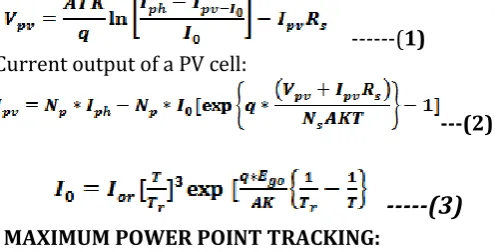
---(1)
Current output of a PV cell:
---(2)
---(3)
MAXIMUM POWER POINT TRACKING:
Studies show that a solar panel converts 30-40% of energy incident on it to electrical energy. A Maximum Power Point Tracking algorithm is necessary to increase the efficiency of the solar panel. There are different techniques for MPPT such as Perturb and Observe (hill climbing method), Incremental conductance, Fractional Short Circuit Current, Fractional Open Circuit Voltage, Fuzzy Control, Neural Network Control etc. Among all the methods Perturb and observe (P&O) and Incremental conductance are most commonly used because of their simple implementation, lesser time to track the MPP and several other economic reasons. Under abruptly changing weather conditions (irradiance level) as MPP changes continuously, P&O takes it as a change in MPP due to perturbation rather than that of irradiance and sometimes ends up in calculating wrong MPP. However this problem gets avoided in Incremental Conductance method as the algorithm takes two samples of voltage and current to calculate MPP [2]. However, instead of higher efficiency the complexity of the algorithm is very high compared to the previous one and hence the cost of implementation increases. So we have to mitigate with a tradeoff between complexity and efficiency. It is seen that the efficiency of the system also depends upon the converter. Typically it is
maximum for a buck topology, then for buck-boost topology and minimum for a boost topology [7]-[8]. When multiple solar modules are connected in parallel, another analog technique TEODI is also very effective which operates on the principle of equalization of output operating points in correspondence to force displacement of input operating points of the identical operating system. It is very simple to implement and has high efficiency both under stationary and time varying atmospheric conditions.
II. EXISTING SYSTEMS
Microcontroller Based Maximum Power Point Tracking For Photovoltaic Solar Panel : Many Solar based Concepts are published in the past and at present time which operate the solar photovoltaic (PV) panel at its maximum power point, by implementing an analogue or digital electronic circuits which are known as maximum power point trackers (MPPT). The main purpose of the researches is to obtain maximum power from the (PV) solar panel under different atmospheric conditions. In this paper a digital technique based on microcontroller type 8051 is used to design and implement the (MPPT) using maximum power point voltage method. The proposed (MPPT) consists of three major units (i) the solar (PV) panel (ii) the DC/DC step down inverter (iii) the control unit and computation of maximum power point based on microcontroller [7]-[8].
Techniques for Maximizing Efficiency of Solar
Energy Harvesting Systems : This topic examines
© 2016, IRJET | Impact Factor value: 4.45 | ISO 9001:2008 Certified Journal | Page 1015 lower cost energy harvesters to bring longer, more
stable operation to the systems.
Fabrication of a Cost effective Automatic Dual/Single Axis Active Solar Tracker with Built in Inverter Designed for Grid Connectivity and
Standalone Systems :In our Dual axis automatic solar
tracker project, AT89S52 micro-controller has been used. Four photo-sensors (LDR VAC54) are used for sensing the sunlight to know sun’s movement. Two gear motors (12V, 300 rpm) are there to rotate the solar panel (E-W and N-S) as the sun changes its direction. ADC chip 0808 is used to decode analog voltage to digital voltage. PROTEUS software coding has been used for designing and simulating the tracker. Photo sensors, battery charging level and solar panel voltage will be monitored by the micro-controller through ADC chip. Attempts have been made to make this pilot project cost-effective with successful completion for standalone systems and can be expanded further for grid connectivity.[5].
Voltage-Based Maximum Power Point Tracking Control of PV System : Photovoltaic (PV) generators exhibit nonlinear V-I characteristics and maximum power (MP) points that vary with solar isolation[4] . An intermediate converter can therefore increase efficiency by matching the PV system to the load and by operating the solar cell arrays (SCAs) at their maximum power point. An MP point tracking algorithm is developed using only SCA voltage information thus leading to current sensor less tracking control. The inadequacy of a boost converter for array voltage based MP point control is experimentally verified and an improved converter system is proposed. The proposed converter system results in low ripple content, which improves the array performance and hence a lower value of capacitance is sufficient on the solar array side. Simplified mathematical expressions for a PV source are derived. A signal flow graph is employed for modeling the converter system. Current sensor less peak power tracking effectiveness is demonstrated through simulation results [1]-[2].
Design and Hardware Implementation of Solar Power Converter with High MPP Tracking:
The system can be implemented by either voltage mode control or current mode control. This work includes a high step up voltage gain DC-DC converter for DC micro grid applications. The DC micro grid can be utilized for rural electrification, UPS support, Electronic lighting systems and Electrical vehicles. The whole system consists of a Photovoltaic panel (PV), High step up DC-DC converter with Maximum Power Point Tracking (MPPT) and DC micro grid. The entire system is optimized with both MPPT and converter separately. The MPP can be tracked by Incremental Conductance (IC) MPPT technique modified with D-Sweep (Duty ratio D-Sweep). D-sweep technique reduces the problem of multiple local maxima. Converter optimization includes a high step up DC-DC converter which comprises of both coupled inductor and switched capacitors. This increases the gain up to twenty times with high efficiency. Both converter optimization and MPPT optimization increases overall system efficiency [7]-[8].
Solar maximum power point tracking system and its application to green house : In this concept a low voltage, low cost & high efficiency based solar maximum power point tracking system for green house applications is presented. The main controlling element is the micro controller program in C language in order to extract maximum solar power point. In addition we use buck converter for MPPT. Further this maximum power is utilized to drive pumps and fans of green house [1]-[2] ,[5]-[6].
© 2016, IRJET | Impact Factor value: 4.45 | ISO 9001:2008 Certified Journal | Page 1016 network created between the nodes. The realization of
the proposed method has been stimulated using simulation at different temperature.
Implementation of Solar Power Optimizer for DC Distribution System using Coupled Inductor and Switched Capacitor : This concept proposes use of a high step up solar power optimizer (SPO) that efficiently reaps maximum energy taken from photo voltaic (PV) panel fed to a DC-micro-grid. The proposed converter employs a switched capacitor and coupled inductor, by varying duty ratio and turns ratios generally we want for the coupled inductor to achieve high step up voltage conversion; The leakage inductance energy of the coupled inductor is efficiently to the load and reduce voltage stress. A rating of low voltage and low-conduction resistance switch makes the system efficiency by employing the perturb and observe (P and O) method for the maximum power point tracking the operating principles and continuous and discontinuous modes , as well as the voltage and current stress of the active switch components are investigated in detail. [1]-[4] A 20V to 40V input voltage, 400V output voltage and 300W output power simulation configuration of the proposed system is implemented to verify the feasibility.
Development of a Microcontroller-Based,
Photovoltaic Maximum Power Point Tracking
Control System : Maximum power point tracking
(MPPT) is used in photovoltaic (PV) systems to maximize the photovoltaic array output power, irrespective of the temperature and irradiation conditions and of the load electrical characteristics. A new MPPT system has been developed, consisting of a Buck-type dc/dc converter, which is controlled by a microcontroller-based unit. The main difference between the method used in the proposed MPPT system and other techniques used in the past is that the PV array output power is used to directly control the dc/dc converter, thus reducing the complexity of the system. The resulting system has high-efficiency, lower-cost and can be easily modified to handle more energy sources (e.g., wind-generators). The experimental results show that the use of the proposed MPPT control increases the PV output power by as
much as 15% compared to the case where the dc/dc converter [7]-[8] duty cycle is set such that the PV array produces the maximum power at 1 kW/m2 and 25 C.
On the use of sun trackers to improve maximum power point tracking controllers applied to photovoltaic systems: Nowadays power supply systems based on photovoltaic cells have two main drawbacks, even the primary energy is free and renewable. They are: production co stand efficiency. In order to increase their efficiency, it should be interesting that the energy transfer between cells and load was done at maximum level. In this paper the use of a sun tracker system is presented as an additional improvement applied to a photovoltaic installation that works under a maximum power point tracking (MPPT) control technique [1]-[4]. A 50W-prototype has been assembled. Some experimental results are also included in order to validate the whole system
III. TRADITIONAL MPPT APPROACHES:
The operating point at maximum power in systems based on PV modules depends on solar-radiation level, operating temperature and load current. So that’s the reason to develop control algorithms in order to ensure that operating point achieves its optimal value.
Main techniques mostly used are:
MPPT based on voltage or current control (VMMPT and CMMPT)
Hill climbing (HC)
Perturbation and Observation (P&O)
Incremental conductance method (Inc.)
Array reconfiguration
Fuzzy logic control
Neural network
Ripple correlation control (RCC)
Current sweep IV. PROBLEM STATEMENT:
© 2016, IRJET | Impact Factor value: 4.45 | ISO 9001:2008 Certified Journal | Page 1017 the cell surface as the isolation, ambient temperature
and current flow varies. Energy conversion using solar (PV) panels is considered one of the best promising techniques in the field of renewable energy sources since photovoltaic (PV) panels uses free and non-exhaustible sunlight as the fuel. Due to pollution and maintenance free (PV) panels are getting increasing worldwide acceptance and applications in various fields. But facing all benefits of (PV) panels as a source of electrical energy in photo voltaic systems, still there are some drawbacks limiting their use at large scale such as low conversion efficiency of the cell and the high initial cost. Beside this and due to the non-linearity characteristics of the solar cell, (PV) systems need to be tracked at maximum power point (MPPT) to obtain maximum power extraction in certain conditions such as sun light, load, and surface temperature[5]-[6]. For the above reason an analogue or digital circuit known as maximum power point tracker (MPPT)[1]-[3] is developed and interfaced between the (PV)panel and the load. The System forces the system operating point towards the (MPP) under all varying operating conditions. In general, the (PV) energy conversion systems of medium and large sizes incorporate three possible approaches of maximizing power extraction. These approaches are sun tracking and (MPPT) or both, however, it is only possible/ feasible to implement (MPPT) for small size systems.
The V-I characteristics of a (PV varies drastically with solar isolation (Light intensity) and the surface temperature) panel are highly non-linear and. It can be noticed that (PV) panel gives maximum power Pmax at a particular voltage and current where the power [4]-[5].
P = V-I is maximum at different operational condition of the characteristics curve. For maximum output power, the internal resistance of the (PV) panel becomes equal the load resistance. The DC/DC step down converter normally achieves the purpose. In this point of View MPPT system has been came into existence so that maximum power can be extracted from PV panel. And the static losses can be removed. While coming to MPPT approaches there are many traditional ways which will be discussed below.
V. PROPOSED TECHNIQUE:
So, In view of all the above problems with traditional approaches we came here with sensor based solar tracking system where the implementation, design of the system is easy and cost effective. And can be implemented to Real Time Environment that is to the Grid system. In our automatic solar tracker concept, AT89C51 micro-controller has been used[6]-[7] . Three photo-sensors (LDR) are used for sensing the sunlight to know sun’s movement.
DC motor (12V, 10rpm) are there to rotate the solar panel (E-W and in center alignment) as the sun changes its direction. ADC chip 0808 is used to decode analog voltage to digital voltage. PROTEUS software coding has been used for designing and simulating the tracker. Photo sensors, battery charging level and solar panel voltage will be monitored by the micro-controller through ADC chip. Attempts have been made to make this pilot project cost-effective with successful completion for standalone systems and can be expanded further for grid connectivity where real time monitoring system is done by using serial communication where time to time alerts will be sent to server room.
© 2016, IRJET | Impact Factor value: 4.45 | ISO 9001:2008 Certified Journal | Page 1018 Figure 2: Schematic diagram of Proposed Concept
BOOST CONVERTER:
[image:6.595.305.560.113.437.2]In many technical applications, it is required to convert a set voltage DC source into a variable-voltage DC output. A DC-DC switching converter converts voltage directly from DC to DC and is simply known as a DC Converter [8] . A DC converter is equivalent to an AC transformer with a continuously variable turns ratio. It can be used to step down or step up a DC voltage source, as a transformer. DC converters are widely used for traction motor control in electric automobiles, trolley cars, marine hoists, forklifts trucks, and mine haulers. They provide high efficiency, good acceleration control and fast dynamic response. They can be used in regenerative braking of DC motors to return energy back into the supply. This attribute results in energy savings for transportation systems with frequent steps. DC converters are used in DC voltage regulators; and also are used, with an inductor in conjunction, to generate a DC current source, specifically for the current source inverter.
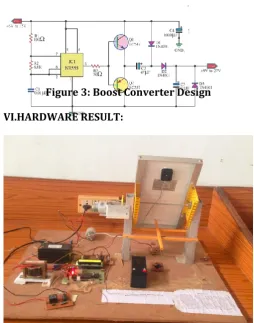
Figure 3: Boost Converter Design
VI.HARDWARE RESULT:
Fig4: solar Panel moving in west direction
© 2016, IRJET | Impact Factor value: 4.45 | ISO 9001:2008 Certified Journal | Page 1019 Fig6: solar Panel moving in center direction
Fig8: Monitoring the solar Panel moving in Center direction and Battery voltage
Fig7: solar Panel moving in East direction
Fig8: Monitoring the solar Panel moving in East direction and Battery voltage
SOLAR PANEL:
Table 1: comparison of solar panel output ranges
Sun ray’s direction
Without tracking With tracking
East Output
Voltage:10V
Output Voltage:11V
Centre Output Voltage:8V Output Voltage:10V
West Output Voltage:5V Output Voltage:10V
Table2: Comparison of Output Results of Boost Converter
Table 3: Design Specifications
SPECIFICATIONS OF COMPONENTS
1. Solar panel : Voltage = 17 V
Open Circuit voltage = 2V Short Circuit Current =0.33A Tolerance = ± 3%
2.Battery Rating: 12V 3.Microcontroller: AT89S52
4. Photo-Sensors: LDRVAC54( Light Dependent Resistor)
5. Motor : 12V, 300 rpm Two gear
motor
6. ADC : 0808
7. Timer : NE555
8. LCD : LM016L (16*2)
9. Transistors : BC 547
10. Resistors : 10 kΩ, 100 kΩ, 200 kΩ,6.5kΩ 11. Capacitors : 0.01µF,47 µF,100 nF
12. Diodes: 1N4001
Fig9 : Overview of Design Input
Voltage
With Load Without
Load
6V 11.58V 13V
7V 12.52V 13.89V
8V 13.26V 17V
9V 16.38V 20.52V
10V 17.69V 22.50V
11V 21.52V 25.06V
© 2016, IRJET | Impact Factor value: 4.45 | ISO 9001:2008 Certified Journal | Page 1020 VII. CONCLUSION
The PV array output power delivered to a load can be maximized using MPPT control systems. It consists of a power conditioner to interface the PV output to the load. In this project, the system consists of a high-efficiency, Boost type dc/dc converter, and a microcontroller based unit which controls the dc/dc converter directly from the PV. And, in this scheme we implemented direct monitoring system which supports in real world. In case of failure of supply manual switches are assembled for tracking to panel. And at discharge of battery more than 75% it will be tripped from the unit and connected to mains.
REFERENCES
1) Arash Shafiei, AhmadrezaMomeni and Sheldon S. Williamson, “A Novel Photovoltaic Maximum Power Point Tracker for Battery Charging Applications,” IEEE, 2012.
2) C.Thulasiyammal and S Sutha, “An Efficient Method of MPPT Tracking System of a Solar Powered Uninterruptible Power Supply Application,” 1st International Conference on Electrical Energy Systems, 2011
3) C. S. Chin, P. Neelakantan, et al., “Fuzzy Logic Based MPPT for Photovoltaic Modules Influenced by Solar Irradiation and Cell Temperature,” UKSim 13th International Conference on Modeling and Simulation, 2011.
4) Chintan, S.S. and Solanki, C.s., “Experimental evaluation of V-trough PV concentrator system using commercial PV modules”, Solar Energy Materials and Solar cells, vol. 91, p.453, 2007. 5) C. Sungur, “Multi-Axes Sun-Tracking System with PLC Control for Photovoltaic Panels in Turkey”, Renewable Energy, 34(2009), pp. 1119–1125.
6) Kais I. Abdul-lateef, “A Low cost single-axis sun tracking system using PIC microcontroller”, Diyala Journal of Engineering Sciences, Vol. 05, No. 01, pp.65-78, June 2012.
7) P.C. M. Bernardo, Z. M. A. Peixoto, L.V.B. Machado Neto, “A high efficient micro-controlled boost converter with maximum power point tracking for photovoltaic systems”, International Conference on Renewable Energies and Power Quality (ICREPQ’09) Spain, April2009.
8) V. Meksarik, S.Masri, S.Taib, C.M.Hadzer, “Development of high efficiency boost converter for photovoltaic application”, National Power& Energy Conference (PECon) 2004 Proceedings, 2004. 9) S.Khader, “Design and simulation of a chopper circuits energized by photovoltaic modules”, 2011 IEEE GCC Conference and Exhibition (GCC) United Arab Emirates, February2011.
BIOGRAPHIES
S. Yasaswini Shirisha, studying B.Tech
in Electrical and Electronics
Engineering Dept. Pragati Engineering College, surampalem, India. Her area of interests are Renewable energy,
Electrical drives, power electronics.
V.Uttej, studying B.Tech in Electrical and Electronics Engineering Dept.
Pragati Engineering College,
surampalem, India. His area of interests are Renewable energy, Electrical drives, power Systems.
Y .Lakshmi Pravallika, studying B.Tech
in Electrical and Electronics
Engineering Dept. Pragati Engineering College, surampalem, India. Her areas of interests are Renewable energy, Electrical drives, Embedded Systems
1’st Author