Full Length Research Article
STUDIES ON ELECTROMAGNETIC ENGINE
*Amarnath Jayaprakash, Balaji, G., Bala Subramanian, S.
and Naveen, N.
Department of Mechanical Engineering, Vel Tech engineering college, Chennai, Tamil Nadu, India
ARTICLE INFO ABSTRACT
Over the last century numerous changes were brought to the internal combustion engines. Numerous researches are carried out in hopes of improving the engine characteristics. Increasing the efficiency and reducing the exhaust gases have been the dominant in the fields of research. The volume and number of applications of engines have grown steadily, penetrating and conquering new markets relentlessly. The exhaust gases contain numerous pollutants that are extremely harmful though in chronic conditions. Hence, Electromagnetic engines were created that uses the combined power of an electromagnet as well as a permanent magnet. These engines cause no air pollution and are a dominant force when this world faces huge crisis due to inadequate fossil fuels. While these engines have already proven their worth as alternative sourced engines, non-polluting and eco-friendly, the current challenge is to make them more efficient and cost effective. This review paper discuss about worldwide review report on the various configurations and their results. Also, this paper concentrates on magnetic damping properties, residual magnetism and the effect of heat on neodymium magnets. A prototype is designed where relay switches are replaced with position sensors. The key reason behind this study is to provide a clear idea of the current existing methods in configuring an electromagnetic engine and to state the existing problems that exist in constructing these engines.
Copyright © 2014. Amarnath Jayaprakash et al. This is an open access article distributed under the Creative Commons Attribution License, which permits unrestricted use, distribution, and reproduction in any medium, provided the original work is properly cited.
INTRODUCTION
Definition of Electromagnetic Engine
An engine powering device with magnetic components that aid in the operation of piston propelled engines by attaching the device individually to the pistons, causing the pistons to perform the up and down thrusts Without the use of fuel thereby mobilizing the engine, eliminating the necessity of fuel and preventing pollution exhausting into the atmosphere. This engine has magnetic shielding safety components to protect people and other electronic devices from strong rare earth magnets and electromagnets.
Principle
An engine powering device with magnetic components that aid in the operation of piston propelled engines by attaching the device individually to the pistons, causing the pistons to perform the up and down thrusts Without the use of fuel thereby mobilizing the engine, eliminating the necessity of
*Corresponding author: Amarnath Jayaprakash,
Department of Mechanical Engineering, Vel Tech engineering college, Chennai, Tamilnadu, India
fuel and preventing pollution exhausting into the atmosphere. This engine has magnetic shielding safety components to protect people and other electronic devices from strong rare earth magnets and electromagnets. A straight current carrying conductor produces a circular magnetic field around itself at all points along its length and that the direction of rotation of this magnetic field depends upon the direction of current flow
through the conductor, the Left Hand Rule. The force that sets
up the magnetic field depends on the number of turns on the coil and the magnitude of the current flowing. This force is called the Magneto Motive Force and the unit of measurement is the Ampere-turn. This equals the current times the number of turns. (MMF = I x n). The material that the magnetic field is being built up in, in this case air, has a resistance to being magnetized. This resistance to the flux build up is called Reluctance. The magnetic field does not appear instantly, it tarts from nothing when the current is first turned on and as the current increases so the magnetic field increases. When the current is turned off the field takes a little time to decade again.
H = (I x N)/L
ISSN:
2230-9926
International Journal of Development Research
Vol. 4, Issue, 3, pp. 519-524, March,2014
International Journal of
DEVELOPMENT RESEARCH
Article History:
Received 30th December, 2013 Received in revised form 23rd January, 2014
Accepted 15th February, 2014
Published online 05th March, 2014
Available online at http://www.journalijdr.com
Key words:
Where:
H - Is the strength of the magnetic field in ampere-turns/metre, At/m
N - Is the number of turns of the coil
I - Is the current flowing through the coil in amps, A L - Is the length of the coil in metres, m
Working
The cylinder, piston and connecting rod appear similar to the conventional Internal combustion engine or it may vary in certain areas. The arrangement completely depends upon the configuration used in designing the electromagnetic engine. It has a permanent magnet, electromagnet, piston, cylinder and connecting rod. Usually Neodymium is used as the permanent magnet and is mounted on top of the piston. Neodymium is either welded or stuck using super glue to keep it from coming out of the piston, while working. The electromagnet is placed in the position of spark plug. The electromagnet is capable of changing the polarity when the direction of the current is changed. The permanent magnet responds to the pull or push of the electromagnet, thereby causing the piston to reciprocate along the length of the cylinder. This power is taken as output from the connecting rod and the crankshaft.
Merits of Electromagnetic Engines
The demand for fossil fuels keeps on increasing and there will be a time when the world will have to depend on electricity as the only source of fuels. Though electric engines are heavy and require more power, they have lesser efficiency when compared to IC engines. A magnetic engine is a promising alternative to the internal combustion engines due to the following factors.
There is no hazard to the surroundings because
electromagnetic engines cause no atmospheric pollution.
Serves as a promising alternative to the fossil fuels.
Better efficiency for operations requiring lesser torque.
Less maintenance is only required.
Lighter than an internal combustion engine.
Literature Survey
Reciprocating motors have been and continue to be used in virtually every available mode of transportation and for all types of power supply needs throughout the entire World. Generally, reciprocating motors have a piston slidably disposed in a cylinder and utilize a driving force to drive the piston in one or both directions inside the cylinder so as to rotate an output shaft, such as a crankshaft. The most commonly utilized reciprocating motor is an internal combustion engine. The typical internal combustion engine comprises a series of cylinders each having a piston reciprocating inside to drive a crankshaft in order to produce motion or power. Air and fuel are combined in the piston chamber, defined inside the cylinder by the top of the piston, and ignited by a spark from a spark plug to provide an explosive driving force that drives the piston downward. The fuel and air are fed into the piston chamber through an intake valve and, after combustion, exhaust air is forced out through an exhaust valve. To obtain proper performance of the fuel/air
igniting sequence, the valve activating mechanism must open and close the intake and exhaust valves at the proper times. Due to relatively high engine operating speeds, this process happens at a very fast rate. Due to their extensive use, the internal combustion engine has been the subject of intensive efforts in India and most countries since the beginning of their utilization to improve the engine’s operating characteristics. Despite these efforts, internal combustion engines are Well known for relatively inefficient utilization of fuel, such as gasoline and other products made from oil, and being significant contributors to the air pollution problems that exist in most cities and towns. As such, the continued use of internal combustion engines is recognized by many persons as a significant draw on the Earth’s limited natural resources and a substantial threat to human health. Other types of reciprocating devices are also well known. For instance, electromagnetic reciprocating engines utilize electromagnetic force as the driving force to move the piston inside the cylinder and rotate the output shaft.
A typical configuration for such engines comprises a plurality of electromagnets disposed around the cylinder that are actuated by electric currents to provide the electromagnetic force necessary to drive the piston in a reciprocating motion in the cylinder. It is well known that this type of electromagnetic engine must have a somewhat large supply of electrical current to power the electromagnets and typically requires complex control mechanism to provide the electrical current to the electromagnets in a manner required to operate the engine. For
these and other practical reasons, electromagnetic
reciprocating engines have generally not become very well accepted. Another source of power that has been utilized to reciprocate a piston inside a cylinder is the magnetic energy stored in permanent magnets. As is well known, when the same polarity ends of two magnets are placed near each other the repulsion force of the two magnetic fields will repel the magnets and, conversely, when the opposite polarity ends of two magnets are placed near each other the attraction force of the magnetic fields will attract the magnets toward each other, assuming one or both of the magnets are allowed to move. A known advantage of utilizing permanent magnets as the driving force for a reciprocating motor is that the energy available from these magnets is relatively constant and capable of providing a long operating life.
In order to use permanent magnets to reciprocally drive a piston inside a cylinder, however, a mechanism must be provided that first utilizes the advantage of dissimilar polarity to attract the piston to the permanent magnet and then utilize the advantage of similar polarity to drive the piston in a way from the permanent magnet. Naturally, this must be done in a very rapid manner at the proper time. The difficulties With being able to rapidly switch polarity when using permanent magnets, as opposed to electromagnetic force, has heretofore substantially limited the ability to utilize the advantages of permanent magnets as a driving force to reciprocate a piston in a cylinder so as to rotate an output shaft for the purposes of motion or the generation of electricity. Over the years, various reciprocating devices that utilize permanent magnets as the driving force to reciprocate a piston or other actuating devices, to one extent or another, have been patented. For instance, US. Pat. No. 3,676,719 to Pecci discloses an electromagnetic motor having an electromagnetic solenoid, located within a
concentric counter bore, having a coil disposed about an inner sleeve and electromagnetic insulating end Walls at the ends thereof. A ferrous metal core is slidably received in the inner sleeve and reciprocates in response to electromagnetic force to rotate a drive shaft. US. Pat. No. 3,81 1,058 to Kiniski discloses a reciprocating device comprising an open-bottomed cylinder having a piston made out of magnetic material, With a predetermined polarity, slidably disposed in the cylinder chamber. A disc that is rotatable is mounted to the engine block below the cylinder has at least one permanent magnet, of like polarity, on the surface facing the open bottom of the cylinder such that the rotation of the disc periodically aligns the permanent magnet With the piston so the repulsive force there between causes the piston to reciprocate in the cylinder chamber. US. Pat. No. 3,967,146 discloses a magnetic motion conversion motor having permanent magnets arranged With like poles facing each other and a magnetic flux field suppressor disposed between the magnets for repeatedly causing a magnetic repelling and attracting action as it is moved into alignment between the like poles of the magnets. The magnets reciprocally drive piston rods connected to crankshafts that are connected to a common drive shaft, as the main output shaft. U.S. Pat. No. 4,317,058 to Blalock discloses an electromagnetic reciprocating engine having a non-ferromagnetic cylinder With a permanent magnetic piston reciprocally disposed therein and an electromagnet disposed at the outer end of the cylinder.
A switching device, interconnecting the electromagnet to an electrical power source, causes the electromagnet to create an electrical field that reciprocates the piston within the cylinder. U.S. Pat. No. 4,507,579 to Turner discloses a reciprocating piston electric motor having a magnetic piston slidably disposed in a nonmagnetic cylinder that has wire coils wrapped around the ends thereof that are electrically activated to reciprocate the piston inside the cylinder to drive a crankshaft connected to the piston by a piston rod. U.S. Pat. No. 5,457,349 to Gifford discloses a reciprocating electromagnetic magnetic engine having fixed magnets mounted in the piston that intermittently attract and repel sequentially energized electromagnets that are radially mounted in the cylinder walls. A computerized control mechanism regulates the timing of the electromagnets to reciprocate the piston and drive a rotatable crankshaft. U.S. Pat. No. 6,552,450 to Harty, et al. discloses a reciprocating engine having a piston, Which is reciprocally disposed in a cylinder, that is driven by opposing electromagnets connected With the piston and cylinder.
A polarity switching mechanism switches polarity to reciprocate the piston. U.S. Pat. No. 7,557,473 to Butler discloses an electromagnetic reciprocating engine comprising an electro magnet with opposing magnetic poles disposed between permanent magnets mounted on either ends of a moving frame connected to a crankshaft. Magnetic attraction and repulsion forces are used to reciprocate the frame and rotate the crank shaft. One of the major disadvantages associated with previously disclosed or presently available permanent magnet reciprocating motors is that mechanism for switching polarity to reciprocally drive the piston in the cylinder generally utilizes one or more electromagnets, which use a switching mechanism interconnecting a power source with the electromagnets. A significant problem with the use of
an electromagnet to reciprocate a piston to or away from a permanent magnet is that the force field of the permanent magnet is strongly attracted to the iron core of the electromagnet. This strong magnetic attraction force makes it very difficult, if not impossible, for the magnetic repelling force to overcome the attraction between the permanent magnet and the iron core, thereby eliminating the repel step (of the attract/ repel action) that is necessary to reciprocate the piston in response to the magnetic switching. If the strong magnetic attraction between the permanent magnet and the iron core can be overcome, it requires an excessive amount of energy for the electromagnet. Other devices utilize an electric motor or other prime mover to rotate or pivot a member having the permanent magnets so as to periodically attract or repel magnets on the piston to provide the force necessary for reciprocating the piston. Naturally, the use of an external prime mover substantially reduces the energy efficiency of the magnetically actuated reciprocating motor and, therefore, one of the primary benefits of such motors.
Another major disadvantage that is associated with presently available magnetically actuated reciprocating motors is that
the switching mechanisms are generally somewhat
complicated and subject to malfunction or cessation of operation. What is needed, therefore, is an improved magnetically actuated reciprocating motor that has an improved mechanism for switching polarities so as to periodically attract and repel a piston-like magnetic actuator to reciprocally move the actuator and rotatably drive an output shaft. An improved reciprocating motor will not utilize iron core electromagnets to attract and repel the magnetic actuator toward or away from a permanent magnet so as to avoid excessive attraction between the permanent magnet and iron core. The reciprocating motor should not rely on a prime mover or the like to reciprocate permanent magnets from an attracting position to a repelling position so as to reciprocally drive a piston disposed in a cylinder. The preferred reciprocating motor should be simple to operate, require a limited number of moving components and be relatively inexpensive to manufacture. The preferred reciprocating motor should connect to a crankshaft or other output shaft to produce rotary power and be adaptable to a Wide variety of reciprocating motor uses, including vehicle motion and power generation.
Factors to Note
Residual Magnetism
In material handling applications where the steel has to pass though automated processing lines, residual magnetism in the load can cause serious problems. The load may ‘stick’ to machine parts as it travels through the production line or it may attract other small pieces of steel (washers, bolts etc). In these situations efficient demagnetization of the load is essential. Smart Pick offers configurable demagnetization for eliminating a maximum amount of residual magnetism in minimum time. Ferromagnetic materials such as such as mild or quality steel which have never been subjected to a magnetic field are made up of randomly ordered magnetic ions as represented below in Figure 1: Steel, when in this state, has no magnetic effect on its surroundings (see point a in Figure 3). When a positive magnetic field is applied, the magnetic ions
start to fall into alignment. The more powerful the magnetic field, the more tightly the ions are aligned. If all of the ions are aligned as shown in Figure 2, the material is said to be magnetically saturated (Point b in Figure 3). For steel the magnetic saturation is equal to 2.4 Tesla.
Figure 1. Ions positioned at random (material demagnetized)
Figure 2. All ions aligned (material magnetically saturated)
Figure 3. Hysteresis of soft magnetic mild steel
However, when the external magnetic field is removed, the ions do not return to their random state. This leaves some residual magnetism in the material, an effect known as remanence (Point c in Figure 3). This residual magnetism has to be removed by some external means. The actual method applied depends mainly on the magnetic properties of the material. Material such as mild steel, loses its magnetism quickly and is said to be ’soft magnetic’. Quality steel on the other hand, loses its magnetism very slowly and is therefore said to be ‘hard magnetic’.
RDS (Reverse Degauss System)
RDS demagnetization eliminates residual magnetism from mild steel. Applying a negative magnetic field causes the magnetic ions to gradually adopt a random alignment. When the opposing field is turned off (Point d in Figure 3), the ions are randomly aligned, thus eliminating the residual magnetism. RDS cannot be applied to hard magnetic material because the negative magnetic field causes all the ions to adopt a reverse alignment instead of returning to a random state.
DDS (Down cycle Degauss System)
DDS reduces the residual magnetism in hard quality steel by applying a series of polarity changes in a magnetic field of ever decreasing amplitude as shown below in Figure 4:
Figure 4. Typical magnet current behavior during DDS demagnetization
With this approach the magnetic ions are effectively ‘shaken’ into a random state, reducing the residual magnetism to around 2 mT.
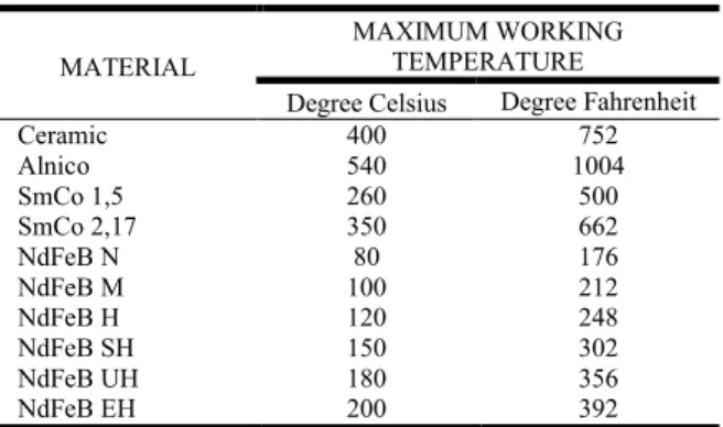
Effect of temperature on magnets
Magnetic materials have a wide range of working temperatures. The following chart lists the various materials and their maximum working temperature. NdFeB material comes in many different heat tolerances but as the heat tolerance increases the maximum available flux density decreases.
Table 1. Effect of temperature on magnets
MATERIAL
MAXIMUM WORKING TEMPERATURE
Degree Celsius Degree Fahrenheit
Ceramic 400 752
Alnico 540 1004
SmCo 1,5 260 500
SmCo 2,17 350 662
NdFeB N 80 176
NdFeB M 100 212
NdFeB H 120 248
NdFeB SH 150 302
NdFeB UH 180 356
NdFeB EH 200 392
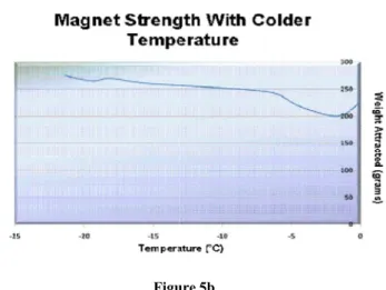
Variation of strength with Temperature
Magnet Strength with Colder Temperature
Table 2. Magnet Strength with Colder Temperature
Temperature (degrees Celsius) Weight Attracted (+/ -21.3
-19.4 -18.1 -15.3 -13.7 -6.7 -4.6 -1.7 0
Magnet Strength with Hotter Temperature
Table 3. Magnet Strength with Hotter Temperature
Time After Removal From Oven
(minutes) Weight Attracted (+/ 0
5 10 20 25 30 35 40 45 50
Figure 5a
523 International Journal of Development Research,
Magnet Strength with Colder Temperature
Magnet Strength with Colder Temperature
Weight Attracted (+/- 2.5 grams) 275
275 265 270 260 245 220 200 225
Magnet Strength with Hotter Temperature
Magnet Strength with Hotter Temperature
Weight Attracted (+/- 2.5 grams)
200 200 240 210 230 220 206 204 200 185
Figu
Figure 5a,5b. Variation of magnetic strength based on temperature
Magnetic Damping
When a magnetic field (magnet
an eddy current is induced in the conductor due to the magnetic field's movement. The fl
conductor creates an opposing magnetic field to the magnet which results in damping of the magnet and causes heating inside of the conductor similar to heat buildup inside of power cords. The loss of energy used to heat up the conduc equal to the loss of kinetic energy by the magnet. differential equation of motion of a magnet dropped vertically through or near a conductor,
Ma = Mg - Kv
Where,
“M” is the mass of the magnet, “K” is the damping coefficient, “v” is the velocity,
“g” is gravity
“a” is the acceleration of the magnet
Hazards
Neodymium magnets larger than 1.5
should be handled with extreme care since they can
high velocities. Neodymium magnets of larger sizes can pinch and even break bones as they are attracted to other
metals with great force & velocities.
Objective of this Invention
From the literature surveys, it is evident that elect
engines are not able to perform as efficient as a conventional internal combustion engine. Though a number of designs and methodologies have been proposed none of them is promising for application in an automobile. So the objective of the project is to develop a new design and methodology to obtain maximum efficiency and to test its performance under different conditions. A new design was developed to overcome the problems. In the new design, two electromagnets were used to attract and repel a piston with smaller diameter and less weight. A permanent magnet with greater force was used to increase the output torque. For more accuracy and precision,
International Journal of Development Research, Vol. 4, Issue, 3, pp. 519-524, March,2014
gure 5b
Variation of magnetic strength based on temperature
magnet) moves through a conductor is induced in the conductor due to the magnetic field's movement. The flow of electrons in the conductor creates an opposing magnetic field to the magnet which results in damping of the magnet and causes heating inside of the conductor similar to heat buildup inside of power cords. The loss of energy used to heat up the conductor is equal to the loss of kinetic energy by the magnet. The differential equation of motion of a magnet dropped vertically
“M” is the mass of the magnet, “K” is the damping coefficient,
“a” is the acceleration of the magnet
Neodymium magnets larger than 1.5 cm are very strong and should be handled with extreme care since they can shatter at high velocities. Neodymium magnets of larger sizes can pinch and even break bones as they are attracted to other magnets or metals with great force & velocities.
From the literature surveys, it is evident that electromagnetic engines are not able to perform as efficient as a conventional internal combustion engine. Though a number of designs and methodologies have been proposed none of them is promising for application in an automobile. So the objective of the t is to develop a new design and methodology to obtain maximum efficiency and to test its performance under A new design was developed to overcome the problems. In the new design, two electromagnets were ston with smaller diameter and less weight. A permanent magnet with greater force was used to increase the output torque. For more accuracy and precision,
sensors and microcontroller were used to actuate the electromagnet according to the position of the piston in the cylinder. From the measured output, application will be decided accordingly.
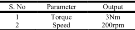
Conclusion
From the developed prototype, the following parameters were observed:
Table 4. Performance measures
S. No Parameter Output
1 Torque 3Nm
2 Speed 200rpm
Though the torque has improved considerably it cannot be used in automobiles. Some of the obstacles to use this engine in an automobile are:
Residual magnetism.
Size of the electromagnets and batteries.
Demagnetization of permanent magnets at higher
temperature.
Speed and torque depends on the size of the battery.
Complicated engine design.
Controlling the engine is difficult.
When considering the above problems, using an
electromagnetic engine in an automobile is practically not possible. But it can be used for various other applications that suit the performance of this engine.
Acknowledgement
We express our sincere thanks to our beloved parents for their invaluable love, moral support and constant encouragement in our lives. We would like to thank the Management of Vel Tech group of Institutions, Avadi, Chennai, for providing immense support throughout the research. We are glad to express our sincere thanks to Prof. J Bharani Chandar, Head of Department, Mechanical Engineering, Vel Tech College for his ceaseless support. We owe immense gratitude to our guide Dr. D. Chandra Mohan, Associate Professor, Department of Mechanical Engineering for his moral support during the course of our Research work. And we express our sincere thanks to Dr. Sumathy Muniamuthu, Associate Professor, Department of Mechanical Engineering, Vel Tech College for her valuable guidance and suggestions.
REFERENCES
[1] Miyuki Blatt & Kendall Houghton. The Effect of
Temperature on Magnet Strength
[2] National Imports LLC .Permanent magnet design and
selection handbook
[3] Vishal Abasaheb Misal, Umesh Dattatray Hajare &
Arshad Ashak Atar. Electromagnetic Engine.
International Journal on Theoretical and Applied Research in Mechanical Engineering (IJTARME). ISSN: 2319 – 3182, Volume-2, Issue-4, 2013.
[4] Gattani M.K. “Gate operated repulsive magnetic
permanent induction linear generator” International journal of Earth Sciences and Engineering, Volume 05 No 01 SPL, Page 702-706, January 2012.
[5] Gattani M. K “Fuel free engine for power generation”
Proceedings of Annual International Conference on Sustainable Energy And Environmental Sciences-2012, Global science and Technology Forum, Singapore, Page 1-5, 13-14th February,2012.
[6] Gattani M.K. “Magnetic engine: Alternate energy source
beyond oil” Proceedings of National conference on Emerging Trends in Energy Engineering-2012, Dehradun Institute of Technology, dehradun, Page 97-101, 23-24th March,2012.
PATENTS
1) Pecci Angelo A; Electromagnetic motor with plural
reciprocating members; US 3676719 A
2) Kiniski Z; Rotary-to-reciprocating device; US 3811058
A
3) Kendall C. Gosvener; Magnetically Charged Solenoid for
Use in Magnetically Actuated Reciprocating Devices; US 20120119594 A1
4) Gerald T. Howard; Magnetic motion conversion device;
US 3967146 A
5) Sherman S. Blalock; Electro-magnetic reciprocating
engine; US 4317058 A
6) Jack C. Turner; Reciprocating piston electric motor; US
4507579 A
7) Leland W. Gifford; reciprocating electromagnetic engine;
US 5457349 A
8) William Thomas Harty; John Thomas Harty;
Reciprocating engine; US 6552450 B2
9) Kala Butler; Electromagnetic reciprocating engine; US
7557473 B2
10) Muneaki Takara; Electromagnetic piston engine; US
6049146 A