© 2017, IRJET | Impact Factor value: 5.181 | ISO 9001:2008 Certified Journal
| Page 1579
Reduction of Inrush current in Three Phase Power Transformers using
SSSC Device
Avinsh Yadav
1, Krishna Kant Sharma
2, Shivani Johri
3, Jyotikant Sharma
41
M.Tech Student (Sri Balaji College of Engineering and Technology, Jaipur)
2
Assistant Professor (Global Institute of Technology, Jaipur)
3
Assistant Professor (Sri Balaji College of Engineering and Technology, Jaipur)
4
Assistant Professor (Sri Balaji College of Engineering and Technology, Jaipur)
---Abstract-
Inrush currents generated by unloaded powertransformer often reduce power quality on the system. To improve this situation, this paper proposes an active inrush current compensator that is capable of reducing the inrush current effectively during startup mode. The proposed compensator is based on an inverter-based series compensator which is comprised of a single-phase inverter and series transformer. This compensator is also called as static series synchronous compensator (SSSC). SSSCs are very frequent events with energization of transformer or starting of large motors although their duration is very short. Hence, during voltage stabilizer mode, the existing series compensator is controlled by a voltage stabilizer controller and superimposes a compensating voltage on the inverter output whenever the load voltage deviate from the nominal value. This strategy is easier to implement because it requires no information of the transformer parameters, power- on angle of circuit breaker and measurement of residual flux.
Transformers, Inrush Current, Residual Flux, SSSC
1. Introduction
Random power transformer energization can create large flux asymmetries and saturation of one or more winding cores of the transformer. This saturation results in high magnitude currents that are rich in harmonic content and have a high direct current component. These currents can cause false operation of protective relays and fuses, mechanical damage to the transformer windings from magnetic forces, and generally reduce power quality on the system. The effects of these transients are normally mitigated by de-sensitizing protective relays or over sizing fuses. Closing resistors have been used to reduce the magnitude of the inrush currents. Controlled closing, or controlling the point on the power frequency voltage wave where energization occurs, has also been employed to reduce these inrush transients.
© 2017, IRJET | Impact Factor value: 5.181 | ISO 9001:2008 Certified Journal
| Page 1580
This paper show the effect of inrush current andharmonics on a three phase transformer and also it shows the reduction of inrush current and harmonics using static synchronous series compensator (SSSC).
2. Inrush Current
[image:2.612.327.537.401.467.2]Transformer works on the principle of mutual flux. At starting when transformer is de energized and again energized the flow of flux depends on the waveform of the flux which remains in the transformer at the time of de energization it which is called residual flux. It means current and flux in the core depends on its switching angle of voltage waveform and residual flux of core. If switching angle and core residual flux are not symmetrical, a high magnitude transient inrush current can develop in the transformer core which may be 10 times greater than its rated no load current. The high magnitude inrush current is very harmful for transformers. It may cause electromagnetic shocks, mal-operation of relays, mechanical damage in brushing and core and windings etc.
Figure 1 Inrush current in transformer
3. Static Synchronous Series Compensator (SSSC)
The SSSC does not use any active power source, the injected voltage must stay in quadrature with line current. By varying the magnitude Vq of the injected voltage in quadrature with current, the SSSC performs the function of
a variable reactance compensator, either capacitive or inductive. The variation of injected voltage is performed by means of a Voltage-Sourced Converter (VSC) connected on the secondary side of a coupling transformer. The VSC uses forced-commutated power electronic devices (GTOs, IGBTs or IGCTs) to synthesize a voltage V_conv from a DC voltage source that shown in fig.2
[image:2.612.41.238.465.588.2]A capacitor connected on the DC side of the VSC acts as a DC voltage source. A small active power is drawn from the line to keep the capacitor charged and to provide transformer and VSC losses, so that the injected voltage Vs is practically 90 degrees out of phase with current I. In the control system block diagram Vd_conv and Vq_conv designate the components of converter voltage Vq_conv which are respectively in phase and in quadrature with current.
Figure 2- Connection diagram of SSSC
4. Simulation Result
4.1 Inrush Current in transformer
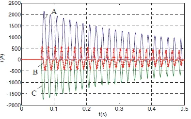
As describe earlier, inrush current generated in power transformers at no load. Inrush current is harmonics rich current. Figure 3,4 and figure 5 shows inrush current in three phase power transformer without using any mitigation technique. These are the current waveform in normal condition when transformer is re-energized.
© 2017, IRJET | Impact Factor value: 5.181 | ISO 9001:2008 Certified Journal
| Page 1581
current as compare to no load current. This inrush currentgoes till 0.4sec. in the transformer. After 0.4 sec. it takes study state condition.
Figure 3 Inrush current in phase A
Figure 4 shows the inrush current in phase B the magnitude of inrush current is 1425 Amp. This inrush current goes till 0.42 sec. in the transformer. After 0.43 sec. it takes study state condition
Figure 4 Inrush current in phase B
Figure 5 show the inrush current in phase C the magnitude of inrush current is 410 Amp. This inrush current goes till 0.35 sec. in the transformer. After 0.35 sec. it takes steady state condition.
Figure 5 Inrush current in phase C
Figure 6 shows the flux in all three phase in transformer. In starting when inrush current generate flux goes in saturation and current increase rapidly for few milliseconds.
Figure 6 Flux of uncompensated system
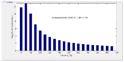
4.2 Harmonics
As discussed earlier, the inrush current is harmonics rich current so it has several harmonics. Figure 7,8 and 9 shows the harmonics in phase A, phase B and phase C.
Figure 7 shows the harmonics in phase A. Total harmonics distortion (THD) in this phase is 25.78 % fundamental component is 72 and second harmonics is 80% in this phase A as shown in figure 8.
Figure 7 Harmonics in phase A
© 2017, IRJET | Impact Factor value: 5.181 | ISO 9001:2008 Certified Journal
| Page 1582
Figure 8 Harmonics in phase BFigure 9 shows the harmonics in phase C. Total harmonics distortion (THD) in this phase is 81.38 %, fundamental component is 48 and second harmonics is 68 % in this phase B as shown in figure 10.
Figure 9 Harmonics in phase
4.3 Mitigated Current-
Figure 10, 11 and 12 shows the current after using prefluxing technique on transformer. The inrush current goes down 99 % by this technique.
Figure 10 Mitigated current in phase A.
Figure 10 shows the mitigated current in phase A. the magnitude of current is 190 Amp which is normal for transformer while without using any technique the current in phase A was 1700 Amp.
Figure 11 Mitigated current in phase B
Figure 11 shows the mitigated current in phase B the magnitude of current is 58 Amp This is normal for transformer while without using any technique, the current in phase B was 1425 Amp.
Figure 12 Mitigated current in phase C
Figure 12 shows the mitigated current in phase C the magnitude of current is 60Amp.This is normal for transformer while without using any technique the current in phase C was 410 Amp.
© 2017, IRJET | Impact Factor value: 5.181 | ISO 9001:2008 Certified Journal
| Page 1583
Figure 13 Flux of compensated system
4.4 Harmonics
[image:5.612.42.576.29.690.2]By using SSSC, the harmonics eliminate from the system. Figure 14, 15 and 16 shows the harmonics in phase A, phase B and phase C.
[image:5.612.41.253.319.425.2]Figure 14 Harmonics in phase A
Figure 14 shows the harmonic in phase A. Total harmonic distortion (THD) in phase A is 17.26 %, while THD without
using SSSC is 25.78%.
Figure 15 Harmonics in phase B
Figure 15 shows the harmonic in phase B. Total harmonic distortion (THD) in phase B is 0.02 % while THD without
using SSSC is 39.12 %.
Figure 16 Harmonics in phase C
Figure 16 shows the harmonic in phase B. Total harmonic distortion (THD) in phase B is 0.02 % while THD without using SSSC is 81.38 %.
Conclusion
The main purpose of this thesis is to mitigate the inrush current and harmonics which is generated in three phase power transformer. This inrush current is very harmful for transformer. The effect and factors of inrush current on power transformer is also described in this thesis. In this thesis, we have investigate inrush current,
harmonics, voltage and flux by using MATLAB®/simulink
model and find the high magnitude starting current and total harmonics distortion in transformer .
These paper shows that SSSC can not only reduce inrush current in power transformer but also it reduce harmonics in the transformers. This compensator can use in both purpose- to compensate transmission line voltage and also to reduce inrush current.
References
1. Gaowa Wuyun ,Po Li and Dichen Liu, “Phase
[image:5.612.33.288.500.632.2]© 2017, IRJET | Impact Factor value: 5.181 | ISO 9001:2008 Certified Journal
| Page 1584
2. A.M. Miri, C Muller, C Sihler, “Modelling of Power
Transformers by a detailed magnetic equivalent circuit” Researchgate publication 228429082.
3. Kunal J Patel, “Effect of Transformer Inrush
Current” thesis, University of Southen Queen land , PP 2539.
4. John H. Brunke, Klaus J. Fröhlich, Senior Member,
IEEE, “Elimination of Transformer Inrush
Currentsby Controlled Switching—Part II:
Theoretical Considerations” IEEE, vol. 16, April2001.
5. Ramsis S. Girgis, Ed G. Tenyenhuis, Member, IEEE,
“Characteristics of Inrush Current of Present Designs of Power Transformers” IEEE, 2007.
6. Hongkui Li1, Yan Li, Xi Sun, DongxuLi,Youteng
Jing, “Analysis of ThreePhase Power Transformer Windings Forces Caused by Magnetic Inrush and ShortCircuit Currents” IEEE, Sept.2009.
7. Chintan R Patel, Sanjay N Patel and Dr. Axay J
Mehta, “Static Synchronous Series Compensator
(SSSC): An approach for reactive power
compensation for the transmission system” National Conference on Recent Trends in Engineering & Technology, 2011.
8. Mariaraj P and Brindha Sakhti B “Enhancement of
Power Fluctuation and Voltage Permanence using FACTS Devices” IJARCSSE, 2014.
9. Raj Kumari, Sanjay Jain and Sanjay Gothwal “
Mitigation of Inrush Current of Transformer using Voltage Sag Compensator” IJARIIT, 2017.