© 2017, IRJET | Impact Factor value: 5.181 | ISO 9001:2008 Certified Journal | Page 884
UTTILITY CURRENT COMPENSATION BY PV-APF SYSTEM USING FUZZY
LOGIC CONTROLLER
B. Suresh Babu
1,C. prasanth sai
2,M.Vijaykumar
31
PG Scholar, Dept. Of Electrical & Electronics Engineering, JNTUA2CEA, Anantapuramu, A.P., India
2Lecturer, Dept. Of Electrical & Electronics Engineering, JNTUACEA, Anantapuramu, A.P., India
3Professor, Dept. Of Electrical & Electronics Engineering, JNTUACEA, Anantapuramu, A.P., India
---***---ABSTRACT- With the widespread use of powerelectronics devices such as rectifier, inverter etc. in power System causes serious problem relating to power quality due to this nonlinear loads currents drawn from the source get distorted and consist of the more no of harmonics so the source current get distorted. For eliminating these harmonics from the source an active power filter is used. In this paper a grid connected PV generator is integrated with the APF faction to eliminate the harmonics drawn from the utility. This system consist of dc/dc boost converter for extracting the maximum power from the PV generator by using the MPPT controller, and consist of dc/ac converter and a nonlinear load.APF function is implemented by using the VSC whose gate pulses is controlled by the APF controller. For designing this APF controller instantaneous power theory is used which shows the reliable performance. This combined system will extract the maximum power and eliminate source harmonics effectively. By replacing the PI controller in APF controller with the Fuzzy logic controller the performance of the system is better.
INDEX TERMS: Active power filter (APF),
instantaneous power theory, photovoltaic (PV), VSC voltage source converter, power quality, renewable energy, fuzzy logic controller.
1. INTRODUCTION
A grid connected PV system or more popular now a day’s which will extract the power in clean environment.The output of the PV unit is connected to the dc/dc boost converter which will extract the maximum power from the PV unit by adapting the maximum power point tracking. By using MPPT technique the duty ratio of dc/dc boost converter is monitored according to the variation of the VI characteristics of the PV cell. The output from the boost converter is given to the dc/ac voltage source converter (VSC). The output from the VSC is fed to the utility and to the nonlinear load. During supplying power to this nonlinear load which will cause drawing nonlinear currents from the utility which will consisting of more harmonics. In this paper the Pv generator should provided with the distorted compensation capability which makes the current drawn from the source become
linear and this functioning can be implemented with active power filter.
For implementing active power filter functioning in the system an APF controller is designed to the VSC which will act as active power filter to reduce the distributed harmonics drawn by the nonlinear loads. For implementing the APF controllers an instantaneous power theory is applied which will give the better performance. This PV system and APF controller will act as a integrated active power filter to the system which will simultaneously compensating the harmonics power factor and current imbalances in the system even there is no availability of power from the PV system this system can capable of eliminating the harmonics and improves the power quality. The basic idea of this paper is using the power references for designing the APF controller which will gives a good improvement in elimination of harmonics .by using this PV APF system gives the better solution to the elimination of harmonics instead of adapting the passive filters or a centralized APF(18).
2. PV-APF COMBINATION SYSTEM
The PV APF system is shown in figure which consists of following.
Fig.1 Proposed design of PV-APF combination.
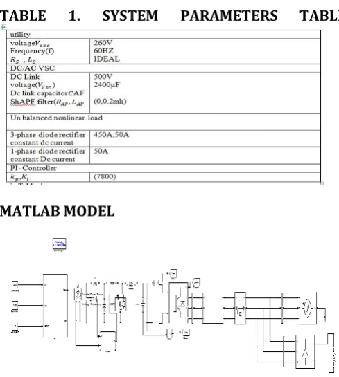
1) The PV system consisting of 5 series and 66 parallel arrays which is sun power SPR-305 delivers power of 100Kw power at 1000W/m2
© 2017, IRJET | Impact Factor value: 5.181 | ISO 9001:2008 Certified Journal | Page 885 incremental conductance method.
3) The dc output from boost converter is connected to 2-level 3-phase dc/ac VSC , this VSC converts the 500V dc to 260V ac at 60HZ then it’s output is connected to the utility and local nonlinear loads.
4) A capacitor bank of rating 10KVAR filter out the switching harmonics produced by VSC.
5) The nonlinear load is a 3-phase diode rectifier supplying current of 450A for 3-phase and 50A for 1-phase.
6) This PV APF combination is tied directly to the utility for active filter implementation.
A. DYNAMIC MODEL OF PV ARRAY
The solar cell is the basic building block of solar photovoltaic. The cell can be considered as a two terminal device which conducts like a diode in the dark and generates a photo voltage when charged by Sun. When charged by the Sun, this basic unit generates a dc photo voltage of 0.5 to 1volt and in short circuit, a photocurrent of some tens of mile amperes per
Fig4.1: Equivalent circuit of PV cell
The output current I of solar arrays is given by using the symbols in figure 4.1
(1)
The cell photocurrent is directly proportional to irradiance. Although cell performance does not degrade significantly but PV cell efficiency depends on incident solar energy. The diode saturation current at the operating-cell temperature is given by
⁄ (
( )) (2) (
⁄ ) (3)
( ) (4)
‘a’ and called the thermal voltage, the ideality factor, is considered constant. According to technology of the PV
cell. The thermal voltage “a” is presented by equation
(5)
(6)
(7)
The output current I after eliminating the diode components is expressed as
* ( ) +
(8)
B.
MPPT IN DC/DC CONVERTER
For the production of maximum power output from the PV cell the operating point of the PV cell is made to operate near knee point of the VI characteristics shown in below fig. At knee point the voltage and currents are Vmax and Imax respectively .The dc/dc boost converter is
set to operate at optimal voltage to extract maximum power . For designing the MPPT controller incremental conductance method is used which will continuously measures the (I/V) ratio. This MPPT method based on the fact that at maximum power point the (dp/dv=0). Based on change in I/V ratio the duty cycle of the boost converter is varied for extracting maximum power. Which is illustrated in below equations
Fig. VI-curve of PV cell
{
© 2017, IRJET | Impact Factor value: 5.181 | ISO 9001:2008 Certified Journal | Page 886 correction for semiconductor switches
3. CONTROLLERS FOR DC/AC CONVERTER
In this section the controllers for the dc/ac VSC is designed based on instantaneous power balance theory . By designing the APF controller to the VSC which will not effect the performance of MPPT controller during the operation. The PV APF controller is used to eliminate the distributed harmonics generated by the nonlinear loads and also extract the maximum power from PV system. Even if there is no availability of power from PV system during this condition also controller will works and compensate the harmonics. During PV APF mode controller made to power drawn from the utility is only average component i.e fundamental component only the remaining oscillating components of power is drawn from PV system. During this condition the entire reactive power is supplied from the PV system only.
A.
PV-APF CONTROLLER
The dc/ac VSC is controlled by APF controller for eliminating the harmonics and reactive power compensation and injecting the maximum power generated by PV system. For designing APF controller is based on instantaneous power theory, the input to the controller is voltages from the utility Vabc and nonlinear
load currents Iabc and currents from the Iabc VSC. The
power consumed by load is supplied by PV unit and utility as shown in below equation.
,
By Using the Clarke trans- formation, the instantaneous real power ( ) and imaginary power ( ) of the load can be calculated, as shown in the following equations:
* ( )+ √ [
√ √
] [
]
* + * + [ ]
The real and imaginary power include two parts: 1) an average (superscript -) one, and 2) an oscillating (superscript ~) one, which are realized through an LPF (or rarely a high-pass filter). The LPF cutoff frequency must be selected carefully as to the inherent dynamics of loads that lead to compensation errors during transients. Unfortunately, the unavoidable time delay of the LPF may degrade the controller performance. In practice, a fifth-order Butterworth LPF with a cutoff frequency between 20 and 100 [Hz] has been used successfully depending on
the spectral components in oscillating part that is to be compensated
{ ̅ ̃
̅ ̃
The average part of the load power is delivered from the utility the remaining oscillating component of real power is supplied from VSC. In this mode the entire reactive power is supplied from the VSC. The utility in this period supply only average component of power so it consisting of only fundamental component so the harmonics from the utility which reduces the THD of utility current
,
̅
̅
While designing the controller the power loss in the system is also considered. After finding the reference powers for VSC inverse clarks transformation is applied for finding 3-phase currents as shown below equations.
[
] √
[
] *
+ (16)
[
] √
[
√ √
] [
] (17)
B. APF CONTROLLER
The APF applications mentioned in [7] use this Akagi technique. The utility currents are not measured by this controller. Only the load currents and the output currents of the APF are measured. The greatest difference of this controller compared with the PV-APF controller is the calculated reference values generated from C VSC, which are oscillating powers as in
,
̅ ̅
̅
In this case, the utility must supply the constant dc-link voltage regulation ̅ .
4. FUZZY LOGIC CONTROLLER
© 2017, IRJET | Impact Factor value: 5.181 | ISO 9001:2008 Certified Journal | Page 887 fuzzy sets for each input and output. ii. Triangular
membership functions for simplicity. iii. Fuzzification using continuous universe of discourse. iv. Implication using Mamdani’s, ‘min’ operator. v. Defuzzification using the height method.
In this system the input scaling factor has been designed such that input values are between -1 and +1. The triangular shape of the membership function of this arrangement presumes that for any particular E(k) input there is only one dominant fuzzy subset. The input error for the FLC is given as
E(k) =
(19)
[image:4.595.57.262.254.400.2]CE(k) = E(k) – E(k-1) (20)
Fig.7. Membership functions
The set of FC rules are derived from
u=-[αE + (1-α)*C] (21)
Where α is self-adjustable factor which can regulate the whole operation. E is the error of the system, C is the change in error and u is the control variable. A large value of error E indicates that given system is not in the balanced state. If the system is unbalanced, the controller should enlarge its control variables to balance the system as early as possible. One the other hand, small value of the error E indicates that the system is near to balanced state.
5. SIMULATION RESULTS
During the period from 0.05s-0.5s simulation starts and pv unit generates power as shown in fig and during this period corresponding duty cycle variation is also shown .From the 0.05s-0.35 the MPPT controller not working from 0.35s MPPT controller extracts maximum power 100kw as shown in the output power variation at 0.35s and corresponding variation of the duty cycle also observed in duty cycle variation at 0.35sec duty cycle of the boost converter will increased at this instant and extracts the maximum power from the PV unit from 0.6s pv unit stops working at that instant power from the PV unit reduced to zero.
The variation of utility current waveform during the run time of the simulation is shown in the below, time
from 0.05s-0.6s nonlinear load draws the power from both utility and PV unit. During the simulation period from 0.05s-0.5s utility supply power to the nonlinear load. After 0.5s PV-APF controller starts working during this period current drawn from the utility will get increased this PV-APF function will stopped at the 0.6s at this instant the power drawn from the PV unit is zero it can observed in real power variation of PV system so the power drawn from the PV source is zero so the entire power will be supplied by the utility only during this mode that’s why current from utility get increased in this period..
The below figures will show the variation if the real and reactive powers of the PV system and utility and load power from 0.05s-0.5s both the utility and PV system will supply the real power to the nonlinear load during this period power drawn from the utility is zero we can observe it from the below waveforms. During the APF mode the PV unit is switched off so the power from PV unit is zero and the entire power will be supplied by the utility only a that period power from the utility is started to increase and during this mode reactive power demand is supplied by the VSC and the reactive power supplied in this period is more compared to the previous case it can observed in the below figures. At the end of 0.7s only utility will supply both real and imaginary powers to load.
TABLE
1.
SYSTEM
PARAMETERS
TABLE
MATLAB MODEL
Fig.8. Matlab model of proposed system with non-linear load.
[image:4.595.309.554.402.675.2]© 2017, IRJET | Impact Factor value: 5.181 | ISO 9001:2008 Certified Journal | Page 888
Fig.9. Matlab model of control circuit with fuzzy logic controller
Fig.10. Matlab model of fuzzy logic controller
MATLAB RESULTS
With fuzzy logic controller
Fig.11. Output power of PV during running time
(a)
(b)
Fig.12. Duty cycle and VPV changed by MPPT. (a) Output voltage of PV unit. (b) Duty cycle of MPPT
Fig.13. Utility supplied current waveform
Fig.14. PV supplied current waveform.
Fig.15. Real power from the (a) utility, (b) PV unit, and (c) load, while the utility supplies power.
Fig.16. Imaginary power from the (a) utility, (b) PV unit, and (c) load, while the utility supplies power.
Fig.17. Utility received current waveform
© 2017, IRJET | Impact Factor value: 5.181 | ISO 9001:2008 Certified Journal | Page 889 Fig.19. Imaginary power from the (a) utility, (b) PV unit,
and (c) load, while the utility receives power
6. CONCLUSION
In this paper the PV system is integrated with the APF is presented this combined system can simultaneously inject the maximum power from the PV system to utility and compensate the distributed harmonics. This PV APF system will not have any impact on MPPT controller for boost converter so this system is extracting the maximum power from the PV system. For designing APF controller instantaneous power theory is used, which will gives the better performances for eliminating the harmonic currents drawn by nonlinear load from utility. Even if there is no power availability from PV system the system can have a capability of eliminating the harmonics. By replacing the PI controller in APF controller with the fuzzy controller the THD of the source current is reduced further and improves the power quality point of view. So from the analysis it is preferably use the PV APF controller to the grid connected system to improve the power quality.
REFERENCES
[1] [1] L. Hassaine, E. Olias, J. Quintero, and M. Haddadi,
``Digital power fac- tor control and reactive power regulation for grid-connected photovoltaic inverter,'' Renewable Energy, vol. 34, no. 1, pp. 315321, 2009.
[2] N. Hamrouni, M. Jraidi, and A. Cherif, ``New control
strategy for 2-stage grid-connected photovoltaic power system,'' Renewable Energy, vol. 33, no. 10, pp. 22122221, 2008.
[3] M. G. Villalva, J. R. Gazoli, and E. R. Filho,
``Comprehensive approach to modeling and simulation of photovoltaic arrays,'' IEEE Trans. Power Electron., vol. 24, no. 5, pp. 11981208, May 2009.
[4] N. R. Watson, T. L. Scott, and S. Hirsch, ``Implications
for distribution networks of high penetration of compact fluorescent lamps,'' IEEE Trans. Power Del., vol. 24, no. 3, pp. 15211528, Jul. 2009.
[5] I. Houssamo, F. Locment, and M. Sechilariu,
``Experimental analysis of impact of MPPT methods on energy efficiency for photovoltaic power systems,'' Int. J. Elect. Power Energy Syst., vol. 46, pp. 98107, Mar. 2013.
[6] M. A. G. de Brito, L. P. Sampaio, G. Luigi, G. A. e Melo,
and C. A. Canesin, ``Comparative analysis of MPPT techniques for PV applications,'' in Proc. Int. Conf. Clean Elect. Power (ICCEP), Jun. 2011, pp. 99104.
[7] M. El-Habrouk, M. K. Darwish, and P. Mehta, ``Active
power filters: A review,'' Proc. IEE Elect. Power Appl., vol. 147, no. 5, pp. 403413, Sep. 2000.
[8] H. Akagi, Y. Kanagawa, and A. Nabae, ``Generalized
theory of the instantaneous reactive power in three-phase circuits,'' in Proc. Int. Conf. Power Electron., Tokyo, Japan, 1983, pp. 13751386.
[9] Y.W. Li and J. He, ``Distribution system harmonic
compensation methods: An overview of DG-interfacing inverters,'' IEEE Ind. Electron. Mag., vol. 8, no. 4, pp. 1831, Dec. 2014.
[10] S. Kim, G. Yoo, and J. Song, ``A bi-functional utility
connected photo voltaic system with power factor correction and UPS facility,'' in Proc. Conf. Rec. 25th IEEE Photo-volt. Specialists Conf., May 1996, pp. 13631368.
[11] Y. Komatsu, ``Application of the extension pq theory to
a mains-coupled photovoltaic system,'' in Proc. Power Convers. Conf. (PCC), vol. 2. Osaka, Japan, 2002, pp. 816821.
[12] L. Cheng, R. Cheung, and K. H. Leung, ``Advanced
photovoltaic inverter with additional active power line conditioning capability,'' in Proc. IEEE Power Electron. Specialists Conf., vol. 1. Jun. 1997, pp. 279283.
[13] T.-F. Wu, C.-L. Shen, C.-H. Chang, and J. Chiu, ``1-
grid-connection PV power inverter with partial active power lter,'' IEEE Trans. Aerosp. Electron. Syst., vol. 39, no. 2, pp. 635646, Apr. 2003.
[14] H. Calleja and H. Jimenez, ``Performance of a grid