http://dx.doi.org/10.4236/jfcmv.2015.32008
Visualization of a Laminar Necklace Vortex
System in Front of a Vertical Rectangular
Plate on a Ground Wall
Yasuhiro Nakahara, Hidemi Yamada
Department of Mechanical and Energy Systems Engineering, Oita University, Oita, Japan Email: [email protected]
Received 23 December 2014; accepted 2 March 2015; published 15 April 2015
Copyright © 2015 by authors and Scientific Research Publishing Inc.
This work is licensed under the Creative Commons Attribution International License (CC BY).
http://creativecommons.org/licenses/by/4.0/
Abstract
Various properties of a necklace vortex system formed around a rectangular plate standing verti-cally on a flat ground wall were investigated by visualizations produced by injecting fluorescent dye into a water channel flow. As a result, it was found that the necklace vortex pattern had three steady systems depending on the Reynolds number Reh, the relative height h/δ of the rectangular plate compared with the laminar boundary layer thickness and the aspect ratio w/h. As it is ex-pected that the aspect ratio of the rectangular plate will typify the projected area configuration of various three-dimensional bodies, the aspect ratio is varied widely from 0.5 to 7.0. The transition-al boundaries of Reh and h/δ in the 2-vortex, 4-vortex and 6-vortex systems for each aspect ratio decreased when w/h < 3.0, and increased when w/h ≥ 3.0 as w/h increased. The x-direction length of the main vortex position XV1/h was almost constant when w/h < 3.0, and decreased when w/h ≥
3.0 as Reh increased. Then, the separation length r1/h increased when w/h < 3.0 and Reh < 1000,
and became almost constant when w/h ≥ 3.0 and Reh ≥ 1000 as w/h and Reh increased. Moreover, the increase of r1/h is notably rapid when w/h < 3.0.
Keywords
Flow Visualization, Necklace Vortex System, Rectangular Plate, Laminar Boundary Layer
1. Introduction
76
between a three-dimensional bluff body and the flat ground wall. Such necklace vortices would be expected to control the flow field near the bluff body and to promote heat transfer between the fluid and wall surfaces.
Baker [1] showed that a steady necklace vortex system around a short cylinder whose diameter to height was 2 was classified into three patterns: a 2-vortex system, a 4-vortex system and a 6-vortex system, based on its Reynolds number and ratio of cylinder diameter to laminar boundary layer thickness by using a critical point concept. Moreover, the unsteady behavior of the necklace vortices was examined using smoke visualization and measurements of vortex frequency by Baker [2] [3] and Thomas [4]. Visbal [5] obtained streamlines of the steady necklace vortices and the unsteady process through the use of numerical calculations. Seal et al.[6] [7] studied a breakaway necklace vortex system in front of a long rectangular cylinder which protrudes through the surface of water. Therefore, the flow field was different from a three-dimensional flow field which flows over a bluff body. Subsequently, Lin et al. investigated the characteristics of a necklace vortex around a slender rec-tangular cylinder [8] and a slender rectangular plate [10] whose width to height in their projected area was from 0.25 to 2.0. They paid attention to the relationship between the primary vortex and the down flow in front of the juncture between the cylinder and the ground wall over a wide range of Reynolds numbers and boundary layer thicknesses, and also discussed the structure of the oscillation and breakaway vortex system in detail. Matsugu-chi et al. [9] displayed a classification map of the necklace vortex system in front of a rectangular cylinder with a width-to-height ratio w/h = 2 in the projected area. Wei et al.[13] [14] experimentally observed the steady necklace vortex and unsteady oscillating vortex in front of a long cylinder with various cross section shapes in-cluding circles, rectangles and prisms. On the other hand, Okamoto et al.[11] showed the existence of a neck-lace vortex at a high Reynolds number through wind tunnel testing of the pressure distributions and oil film pat-terns observed on the ground wall surface around rectangular plates with width-to-height ratios 2, 4 and 7. Moreover, Sakamoto et al.[12] measured the surface pressure distribution on rectangular plates with width-to- height ratios from 0.5 to 10 submerged in turbulent boundary layer flows, and suggested the existence of a tur-bulent necklace vortex. However, in many traditional investigations, the characteristics of the necklace vortex system over the wide range of width-to-height ratios in projected areas of three-dimensional bluff bodies have largely remained unrevealed. Then, if a rectangular plate is employed as the typical shape of three-dimen- sional bluff bodies, the width-to-height ratio in the projected area may be replaced with the aspect ratio of the plate.
Therefore, the aim of this study is to clarify the effect of the aspect ratio, the Reynolds number and the rela-tive height concerning with the rectangular plate on the characteristics of the laminar necklace vortices. A thin rectangular plate with a sharp edge standing vertically on a flat ground wall was selected as the basic bluff body and was mounted on the wall. The shape of the rectangular plate could be described by using only the aspect ra-tio w/h defined as a rara-tio of the plate width w to the plate height h. It may be expected that the characteristics of the necklace vortex system, such as the shape and locations of the separation line around the three-dimensional bluff body on the ground wall and the number and locations of the necklace vortices, strongly depend on the as-pect ratio. Therefore, the asas-pect ratio was varied widely. The overall effect of the asas-pect ratio w/h, the relative height h/δ defined as the ratio of a plate height h to the laminar boundary layer thickness δ and the Reynolds number Reh based on the plate height h and the nominal tip velocity Uh, on the characteristics of necklace
vor-tices was investigated by using visualization techniques.
2. Experimental Apparatus and Procedure
The experimental Reynolds number Reh (=Uh∙h/ν) was defined based on the plate height h and the nominal
tip velocity Uh at the same y-position as the upper tip of the plate in the approaching flow. The Reynolds number
Reh was in the range of 100 - 1800. However, because the unsteady vortex system was observed in the region of about Reh > 500 in the case of w/h = 3.0 - 7.0, the experiment was hardly carried out under these conditions, as shown in Figure 5. The nominal tip velocity Uh and the laminar boundary layer thickness δ99 was estimated
based on Blasius’ solution by using free stream velocity U0 and the length from the leading edge of the ground
wall to the rectangular plate position. U0 was determined by measuring 7 times dye moving speeds in the
x-distance of 500 mm. The patterns of the necklace vortex system on a symmetrical plane were observed as the streak lines of the fluorescent dye injected from a small tracer tube set in various positions away from the ground wall, and in the separation line around the rectangular plate being observed as a curve line formed by dye injected from small holes of 0.8 mm diameter along the center line on the ground wall. The behavior of the dye was illuminated by a metal halide light source with slit width of 2 mm. The visualization images were taken by a film still camera with a shutter speed of (1/15) second, and were digitized into a BMP format by using a scanner with resolutions of 9 - 26 pixel/mm.
3. Experimental Results and Discussions
3.1. Visualization and Classification of Necklace Vortex System
[image:3.595.173.453.374.565.2]To clarify the characteristics of the necklace vortex system produced in front of the rectangular plate, the influ- ence of the Reynolds number Reh, relative height h/δ and aspect ratio w/h upon the pattern of necklace vortices formed on the symmetrical plane was discussed.Figure 2exhibits the pattern of the necklace vortex system on the symmetrical plane upstream of a rectangular plate with the aspect ratios of w/h = 3.0, 5.0 and 7.0, respec-tively. The Reynolds number and relative height are kept at about Reh = 400 and h/δ = 1.1. It is clear that the
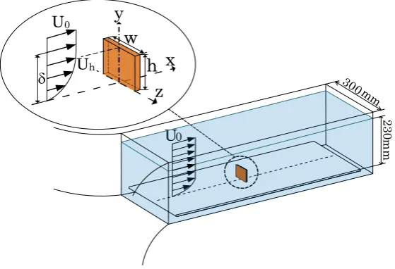
Figure 1. Schematic diagram of experimental apparatus and coordinate system.
Table 1.Variation of blockage ratio for rectangular plates used in this experiment.
Aspect ratio w/h Plate height h
10 mm 15 mm 20 mm 25 mm 35 mm 55 mm
0.5 0.07% - 0.29% - 0.89% -
1.0 0.14% - 0.58% - 1.78% 4.38%
2.0 0.29% 0.65% 1.16% 1.81% 3.55% -
3.0 0.43% - 1.74% - - -
5.0 0.72% - - - - -
7.0 1.01% - - - - -
U0
300mm
23
0m
m
h
w
z
x
y
U0
78
different necklace vortex systems are formed depending on the conditions of Reh, w/h and h/δ. Once the values of Reh, w/h and h/δ are determined, the only steady and laminar necklace vortex is formed, and other vortex system is not formed on one’s way to the only vortex system. The formed vortex system is not varied with the lapse of time. As shown inFigure 2(a), in the case of w/h = 3.0 there are two obvious clockwise vortices. From the viewpoint of flow pattern topology, it is predicted that two counter-clockwise vortices must exist in the tri-angular region that adjoins upstream of each clockwise vortex, therefore a small clockwise vortex must exist in front of these clockwise vortices, and another counter-clockwise vortex exists in the small corner between the plate and the ground wall. Here, the typical flow pattern of a 6-vortex system based on topology is shown in
Figure 3. In this case, there exists three clockwise vortices called V1, V2 and V3. Therefore, the flow pattern
shown inFigure 2(a) is considered to be almost a 6-vortex system, but as the most upstream clockwise vortex V3 is extremely small and not visualized, then it may be a vortex pattern existing between the 6-vortex and the
4-vortex systems.
In the case of w/h = 5.0, the flow separating from the ground wall forms a second clockwise vortex V2 as
shown inFigure 2(b). This signifies that the system clearly becomes a 4-vortex system. In the case of w/h = 7.0, a large clockwise vortex clearly entrains the separating flow upstream of the plate as shown inFigure 2(c). In this case, since a small counter-clockwise vortex must exist in the small corner between the plate and the ground wall, this flow pattern is called a 2-vortex system. The result above indicates that as the aspect ratio increases, the number of necklace vortices decreases.
Figure 4 shows the necklace vortex system with aspect ratio w/h = 3.0 and 7.0. Though the relative height is also considered to be close to that ofFigure 2, the Reynolds number is slightly larger than that ofFigure 2. It was noticed that the 4-vortex or 6-vortex systems in Figure 2(a) has transformed into the 6-vortex system in
Figure 4(a), and the 2-vortex system inFigure 2(c) has become the 4-vortex system inFigure 4(b). The com-parison ofFigure 2 andFigure 4 shows that even if the aspect ratio is the same, the vortex pattern has a ten-dency to change into larger vortex systems as the Reynolds number increases.
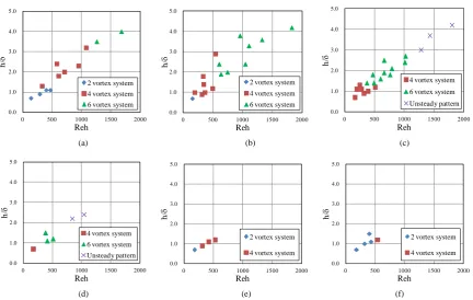
For the next step, the variation of the vortex system was systematically examined for a wide range of aspect ratios w/h, Reynolds numbers Reh and relative heights h/δ. Figures 5(a)-(f) show the classifications of the necklace vortex systems in terms of Reh and h/δ for aspect ratios w/h = 0.5, 1.0, 2.0, 3.0, 5.0 and 7.0, respec-tively. The necklace vortex pattern is classified into the 2-steady-vortex, 4-steady-vortex and 6-steady-vortex systems. The stationarity of the vortex systems were determined by the maintenance of the dye trajectory which exhibits the shape of the vortex pattern. The unsteady vortex pattern in the case of high Reynolds number and
(a) (b) (c)
Figure 2. Pattern of necklace vortex system on symmetrical plane in front of a rectangular plate: (a) w/h = 3.0, Reh = 410; (b) w/h = 5.0, Reh = 420; (c) w/h = 7.0, Reh = 440.
Figure 3. Typical flow pattern of the 6-vortex system (w/h = 2.0, Reh = 800, h/δ = 2.0).
Flow direction
h
Stagnation point
V1 V2
V3
Separation length r1
XV1
YV
the boundary between the steady and unsteady vortex patterns is not handled in this study. By and large, it was noted that the necklace vortex system occurs depending on the Reynolds number Reh, the relative height h/δ and the aspect ratio w/h. The vortex system becomes larger for each w/h with increasing Reh and h/δ. In addition, it is understood that the effect of Reh and h/δ on the transition boundary between the different vortex systems is approximately similar for each aspect ratio w/h. In the present experimental range, the 2-vortex system was not observed in the aspect ratio w/h = 2.0 and 3.0. The boundary between the steady and the unsteady regimes also shifts to small values of Reh and h/δ in the same aspect ratio condition. On the other hand, in the case of aspect ratio w/h ≥ 3.0, the 2-vortex system is observed again in the region of low Reynolds number.
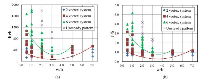
Figure 6summarizes the transitional boundaries of Reh and h/δ in the 2-vortex, 4-vortex and 6-vortex sys-tems for each as pect ratio w/h. In the case of about w/h ≤ 3.0, the transitional boundaries of Reh and h/δ shown in dotted lines decrease as w/h increases. In the case of about w/h ≥ 3.0, their transitional boundaries increase as w/h increases. Therefore, it seems that the necklace vortex system forming in front of the rectangular plate changes the formation mechanism around the aspect ratio of about w/h = 3.0.
[image:5.595.173.457.300.387.2]3.2. Variation of Necklace Vortex Position
Figure 7shows XV1/h for Reynolds number Reh at each aspect ratio w/h. XV1 is the x-direction vortex position
[image:5.595.99.532.421.695.2](a) (b)
Figure 4. Pattern of necklace vortex system on symmetrical plane in front of a rectangular plate: (a) w/h = 3.0, Reh = 510; (b) w/h = 7.0, Reh = 530.
(a) (b) (c)
(d) (e) (f)
Figure 5. Classification map of necklace vortex system for the combination of Reh and h/δ at each aspect ratio: (a) w/h = 0.5; (b) w/h = 1.0; (c) w/h = 2.0; (d) w/h = 3.0; (e) w/h = 5.0; (f) w/h = 7.0.
Flow direction
(a) (b)
0.0 1.0 2.0 3.0 4.0 5.0
0 500 1000 1500 2000
h/
δ
Reh
2 vortex system 4 vortex system 6 vortex system
0.0 1.0 2.0 3.0 4.0 5.0
0 500 1000 1500 2000
h/
δ
Reh
2 vortex system 4 vortex system 6 vortex system
0.0 1.0 2.0 3.0 4.0 5.0
0 500 1000 1500 2000
h/
δ
Reh
4 vortex system 6 vortex system Unsteady pattern 0.0 1.0 2.0 3.0 4.0 5.0
0 500 1000 1500 2000
h/
δ
Reh
4 vortex system 6 vortex system Unsteady pattern 0.0 1.0 2.0 3.0 4.0 5.0
0 500 1000 1500 2000
h/
δ
Reh
2 vortex system
4 vortex system
0.0 1.0 2.0 3.0 4.0 5.0
0 500 1000 1500 2000
h/
δ
Reh
2 vortex system
80
[image:6.595.111.537.79.232.2]
(a) (b)
Figure 6. Classification map of necklace vortex system for various aspect ratios: (a) Reynolds number Reh range; (b)
Rela-tive height h/δrange.
[image:6.595.142.492.270.431.2](a) (b)
Figure 7. The x-direction vortex position length XV1 for Reynolds number Reh: (a) w/h = 0.5 and 1.0; (b) w/h ≥ 2.0.
length from the rectangular plate to the center position of main necklace vortex V1. A center position of the
vor-tices is defined as the center of the fluorescent dye that was rotating in the vorvor-tices on a symmetrical plane. In the case of w/h ≤ 1.0, XV1/h is constant over a wide range in terms of the Reynolds number Reh, but gradually
decreases as Reh increases in the case of w/h ≥ 2.0. In addition, XV1/h decreases with w/h decreasing under w/h
< 2.0. The flow approaching the plate forms a stagnation point on the plate front surface. A down-reverse flow from the stagnation point pushes the necklace vortices upstream, and then causes the formation of the necklace vortex system. By decreasing w/h, the flow in the plate side direction becomes dominant, and the down-reverse flow becomes relatively weak. Therefore, it is thought that XV1/h is low value with w/h decreasing. On the other
hand, XV1/h is slightly decreased in the case of w/h > 2.0, because the vortex tube is stretched in the plate width
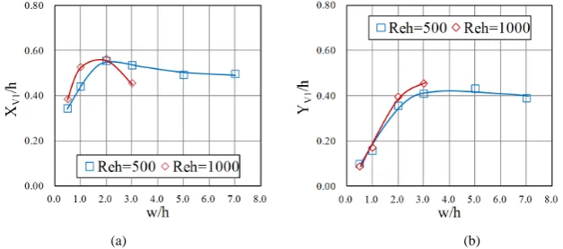
direction with increasing w/h. It seems to indicate that the formation mechanics of necklace vortices has gradu-ally altered in the case of w/h > 2.0. The tendency that XV1/h shifts in the case of w/h = 2.0 is clearly observed in Figure 9(a) which shows the variations of XV1/h at Reh = 500 and 1000.
Figure 8shows YV1/h for Reynolds number Reh at each aspect ratio w/h. YV1 is the y-direction vortex
posi-tion length from the ground wall to the center posiposi-tion of main necklace vortex V1. YV1/h has a tendency to alter
the variation of Reh. In the case of w/h = 0.5 and 1.0, YV1/h decreases as Reh increases. On the other hand, in
the case of w/h = 2.0, YV1/h increases and peaks at about Reh = 800, and then decreases as Reh increases.
Fur-ther variation of YV1/h seems to produce a similar tendency for the aspect ratios of w/h ≥ 2.0.Figure 9(b) shows
YV1/h for the various w/h at Reh = 500 and 1000. YV1/h rapidly increases with increasing w/h in the case of w/h
≤ 2.0, and becomes gradually constant in the case of about w/h ≥ 2.0. These results show that the variation in the necklace vortex formation position is light for the Reynolds number and rapid for small aspect ratios as shown in Figure 8andFigure 9,and suggest that the transition of the vortex system hardly affects the formation posi- tion and scale of the main necklace vortex.
0 400 800 1200 1600 2000
0.0 1.0 2.0 3.0 4.0 5.0 6.0 7.0
R
eh
w/h
2 vortex system
4 vortex system
6 vortex system
Unsteady pattern
0.0 1.0 2.0 3.0 4.0 5.0 6.0
0.0 1.0 2.0 3.0 4.0 5.0 6.0 7.0
h/
δ
w/h
2 vortex system
4 vortex system
6 vortex system
(a) (b)
Figure 8. The y-direction vortex position length YV1 for Reynolds number Reh: (a) w/h = 0.5 and 1.0; (b) w/h ≥ 2.0.
(a) (b)
Figure 9. Vortex position length for various aspect ratios at Reh = 500 and 1000: (a) XV1/h; (b) YV1/h.
3.3. Variation of Separation Line
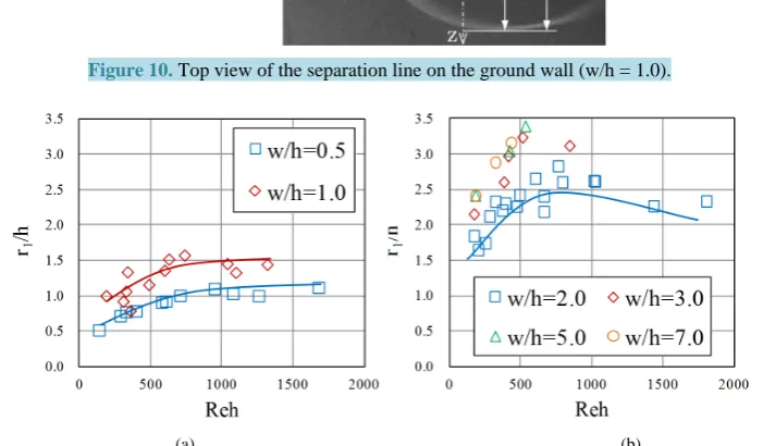
The spread of the necklace vortices region can be known by observing a separation line on the ground wall.
Figure 10shows the top view of a separation line around the rectangular plate (w/h = 1.0). The visualization dye was injected from a small hole just downstream of the separation point on the wall surface along x-axis. It moves once upstream of the hole, and surrounds the rectangular plate on the wall surface. In this study, the shape of the separation line is determined by separation lengths r1 and r2 from the coordinate origin to the
sepa-ration point, measured as the outer edge of the dye in the x and z-directions, and the sepasepa-ration length r3 from
the side edge of the plate to the separation point in the z-direction.
Figure 11 shows the relative separation length r1/h in the x-direction for Reynolds number Reh in various
as-pect ratios w/h. In the case of w/h = 0.5 and 1.0, r1/h gradually increases with increasing Reh, and becomes
al-most constant under Reh ≥ 1000. In the case of w/h = 2.0 r1/h becomes large and has a gentle peak at about Reh
= 800, and then in the case of w/h ≥ 2.0 it seems to have the same tendency as the case of w/h = 2.0. This ten- dency of r1/h is similar to that of YV1/h of decreasing as Reh increases. The rapid increase of r1/h in w/h = 2.0 is
due to the increase in the rate of the down-reverse flow as the plate width increases.Figure 12shows the rela-tive separation length r3/h in the z-direction for each Reh. The separation length r3/h increases with increasing
Reh, and becomes almost constant in the region of about Reh ≥ 1000.Figure 13 shows the separation lengths r1/h and r3/h for each aspect ratio at Reh = 500 and 1000. Both r1/h and r3/h show the same variation patterns that
increases with increasing w/h in the case of w/h < 3.0 and approach constant values in the case of w/h ≥ 3.0. The value of r1/h and r3/h is almost equal in the case of w/h < 1.0, but r3/h is always smaller than r1/h in the case of
w/h ≥ 1.0. By and large, it is noted that variation of r1/h and r3/h for w/h is similar to that of XV1/h and YV1/h.
It is considered that the separation length r1 and the main vortex position length XV1 are closely related. The
relationship between r1 and XV1 was examined in terms of the Reynolds number Reh for each aspect ratio as
[image:7.595.157.471.259.398.2]82
Figure 10. Top view of the separation line on the ground wall (w/h = 1.0).
[image:8.595.138.489.187.392.2](a) (b)
Figure 11. The x-direction separation length r1 for Reynolds number Reh: (a) w/h = 0.5 and 1.0; (b) w/h ≥ 2.0.
(a) (b)
Figure 12. The z-direction separation length r3 for Reynolds number Reh: (a) w/h = 0.5 and 1.0; (b) w/h ≥ 2.0.
XV1/r1 decreases slightly with increasing Reh in the region of Reh < 1000 and becomes almost constant at about
Reh ≥ 1000. Moreover, XV1/r1 decreases slightly with increasing w/h in the case of about w/h < 3.0 and
ap-proaches a constant value of about 0.15 in the case of w/h ≥ 3.0.
4.
Conclusions
[image:8.595.133.497.423.587.2](a) (b)
Figure 13. The x-direction separation length r1 for various aspect ratios at Reh = 500 and 1000: (a) r1/h; (b) r3/h.
(a) (b)
Figure 14. Relationship between the vortex position length and the separation length in x-direction for Reynolds number Reh: (a) w/h = 0.5 and 1.0; (b) w/h ≥ 2.0.
Figure 15. Relationship between the vortex position length and the separation length in x-direction for various aspect ra-tios at Reh = 500 and 1000.
[image:9.595.132.495.271.426.2] [image:9.595.207.422.463.648.2]84
system is large at each w/h with increasing Reh and h/δ.
2) The transitional boundaries of Reh and h/δ forming the 2-vortex, 4-vortex and 6-vortex systems for each aspect ratio decrease in the case of w/h < 3.0, and increase in the case of w/h ≥ 3.0 as w/h increases.
3) The x-direction main vortex position length XV1/h is almost constant in the case of w/h < 3.0, and decreases
in the case of w/h ≥ 3.0 with increasing Reh.
4) The x-direction separation length r1/h increases in the case of w/h < 3.0 as w/h increases, and becomes
al-most constant in the case of w/h ≥ 3.0. Moreover, r1/h increases in the case of Reh < 1000 as Reh increases, and
becomes almost constant in the case of Reh ≥ 1000.
5) The ratio XV1/r1 of the main vortex position length to the separation length gradually approaches a constant
value of 0.15 in the case of w/h ≥ 3.0 and Reh ≥ 1000.
Acknowledgements
The authors would like to thank T. Shibata, Y. Furukawa and N. Arisawa for their helpful discussion during the course of this experiment.
References
[1] Baker, C.J. (1979) The Laminar Horseshoe Vortex. Journal of Fluid Mechanics, 95, 347-367.
http://dx.doi.org/10.1017/S0022112079001506
[2] Baker, C.J. (1980) The Turbulent Horseshoe Vortex. Journal of Wind Engineering Industrial Aerodynamics, 6, 9-23.
http://dx.doi.org/10.1016/0167-6105(80)90018-5
[3] Baker, C.J. (1991) The Oscillation of Horseshoe Vortex Systems. Journal of Fluids Engineering, 113, 489-495.
http://dx.doi.org/10.1115/1.2909523
[4] Thomas, A.S.W. (1987) The Unsteady Characteristics of Laminar Juncture Flow. Physics of Fluid, 30, 283-285.
http://dx.doi.org/10.1063/1.866374
[5] Visbal, M.R. (1991) Structure of Laminar Juncture Flows. AIAA Journal, 29, 1273-1281.
http://dx.doi.org/10.2514/3.10732
[6] Seal, C.V., Smith, C.R., Akin, O. and Rockwell, D. (1995) Quantitative Characteristics of a Laminar Necklace Vortex System at a Rectangular Block-Flat Plate Juncture. Journal of Fluid Mechanics, 286, 117-135.
http://dx.doi.org/10.1017/S002211209500067X
[7] Seal, C.V., Smith, C.R. and Rockwell, D. (1997) Dynamics of Vorticity Distribution in Endwall Junctures. AIAA Journal, 35, 1041-1047. http://dx.doi.org/10.2514/2.192
[8] Lin, C., Ho, T.C. and Dey, S. (2008) Characteristics of Steady Horseshoe Vortex System near Junction of Square Cy-linder and Base Plate. Journal of Engineering Mechanics, 134, 184-197.
http://dx.doi.org/10.1061/(ASCE)0733-9399(2008)134:2(184)
[9] Matsuguchi, A., Kagawa, N., Tsuda, N. and Tsuruno, S. (1999) Study on Transition Process of Horse-Shoe Vortex.
Transaction of the Japan Society of Mechanical Engineers, Series B, 65, 28-35. (In Japanese)
http://dx.doi.org/10.1299/kikaib.65.28
[10] Lin, C., Chiu, P.H. and Shieh, S.J. (2002) Characteristics of Horseshoe Vortex System near a Vertical Plate-Base Plate Juncture. Experimental Thermal and Fluid Science, 27, 25-46. http://dx.doi.org/10.1016/S0894-1777(02)00215-7
[11] Okamoto, S., Kobayashi, M., Kadono, T., Kagaya, H. and Shimane, A. (2005) Flow Past a Plate of Finite Width Placed Vertically on a Ground Plane. Transaction of the Japan Society of Mechanical Engineers, Series B, 71, 2663-2670. (In Japanese) http://dx.doi.org/10.1299/kikaib.71.2663
[12] Sakamoto, H., Moriya, M., Taniguchi, S. and Arie, M. (1981) Flow around a Normal Plate of Finite Width Immersed in Turbulent Boundary Layer: 1st Report, Pressure and Drag Acting on Plate. Transaction of the Japan Society of Me-chanical Engineers, Series B, 48, 1674-1682. (In Japanese) http://dx.doi.org/10.1299/kikaib.48.1674
[13] Wei, Q.D., Chen, G. and Du, X.D. (2001) An Experimental Study on the Structure of Juncture Flows. Journal of Visu-alization, 3,341-348. http://dx.doi.org/10.1007/BF03181728
Nomenclatures
h: Height of rectangular plate [m] h/δ: Relative height of rectangular plate Reh: Experimental Reynolds number
r1 and r2: x- and z-direction separation lengths from the origin to the separation points [m]
r3: z-direction separation length from the rectangular plate side edge to the separation point [m]
Uh: Nominal tip velocity [m/s]
U0: Free stream velocity [m/s]
w: Width of rectangular plate [m] w/h: Aspect ratio of rectangular plate (x, y, z): Cartesian coordinate system
XV1 and YV1: x-direction and y-direction lengths from the origin to the center position of main vortex V1 [m]
δ: Laminar boundary layer thickness(=δ99) [m]