Continuous Phase Modulation for Digital Video
Broadcasting
Khaled A. Ramadan
1, Emad S. Hassan
2, Xu Zhu
3, Mohammed Abd-Elnaby
2, EL-Sayed M.
El-Rabaie
2, Fathi E.Abd El-Samie
21
ERTU, Cairo, Egypt.
2
Department of Electronics and Electrical Communications, Faculty of Electronic Engineering, Menoufia University, Menouf, 32952, Egypt.
3
Department of Electrical Engineering and Electronics, University of Liverpool, L69 3GJ, U.K.
ABSTRACT
In this paper, we study the performance of the Digital Video Broadcasting- Terrestrial (DVB-T) system with Continuous Phase Modulation Orthogonal Frequency Division Multiplexing (CPM-OFDM). The proposed structure combines the advantage of mitigating the Peak-to-Average Power Ratio (PAPR) problem in the Power Amplifier (PA)in addition to exploiting the channel frequency diversity and power efficiency of CPM. The proposed CPM-OFDM DVB-T system is implemented with Frequency-Domain Equalization (FDE) to avoid the complexity of the equalization. Two types of frequency domain equalizers are considered and compared for performance evaluation of the system; the Zero-Forcing (ZF) equalizer and the Minimum Mean Square Error (MMSE) equalizer. Simulation results show that the performance of the CPM-OFDM DVB-T system with multi-path fading is better than its performance with single-path fading.
Keywords
DVB-T; OFDM; CPM; ZF Equalizer; MMSE Equalizer; PAPR.
1.
INTRODUCTION
In the terrestrial transmission of digital TV signals according to the DVB standard, it was decided that the most appropriate modulation method to cope with transmission problems would be OFDM [1].OFDM is an effective multicarrier transmission technique for wireless communications, because it provides a high degree of immunity to multi-path fading and impulsive noise, and it eliminates the need for complicated equalizers [2,3]. One of the major drawbacks of multicarrier transmission is the high PAPR of the transmitted signals. This problem makes OFDM sensitive to nonlinear distortions caused by the transmitter PA[4]. Without sufficient power back-off, the DVB-T system suffers from spectral broadening, intermodulation distortion, and consequently, performance degradations. These problems can be solved by increasing the Input Power Back-off (IBO), but this leads to a reduction in the efficiency of the PA [5, 6].
Several techniques have been proposed to solve the PAPR problem such as clipping and filtering, coding, Tone Reservation (TR), Tone Injection (TI), and multiple signal representation techniques, such as the Partial Transmit Sequence (PTS) technique, the selective mapping (SLM) technique, and the interleaving technique[7–13]. These techniques achieve a PAPR reduction at the expense of an increase in the transmitted signal power, the Bit Error Rate
(BER), and the computational complexity. An alternative approach to mitigating the PAPR problem is based on signal transformations. This technique involves a signal transformation prior to amplification, then an inverse transformation at the receiver prior to demodulation. In [14,15], a Phase Modulator (PM) transform was considered to generate signals with CPM. This scheme is attractive for wireless communications because of the constant envelope of the generated signals, which is needed for power efficient transmitters, and its ability to exploit the diversity of the multi-path channel, which is needed to improve the BER performance. In the CPM-OFDM DVB-T system, the OFDM signal is used to phase-modulate the carrier. This system shares many of the same functional blocks with the conventional DVB-T system. This makes the existing DVB-T systems capable of providing an additional CPM-OFDM DVB-T mode, easily.
The objective of this paper is to study the performance of the CPM-OFDM for the DVB-T system in addition of comparing performance with the conventional DVB-T system performance. The rest of this paper is organized as follows. Section 2 presents the CPM-OFDM DVB-T system model. In Section 3, the design of the frequency-domain equalizers is discussed. Section 4, presents the phase demodulator. Section 5presents both the bandwidth efficiency and multi-pathdiversity of CPM Signals. Section 6 provides the numerical results and the discussion. Finally, Section 7 provides some concluding remarks.
2
.
The CPM-OFDM for DVB-T System
Model
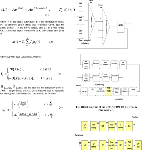
The block diagram of both CPM-OFDMDVB-T system and CPM-OFDM system are shown in Figs. (1)and(2). Let X(k) denote the M-ary quadrature amplitude-modulated (QAM) data symbols. During each T-second block interval, an NDFT points Inverse Discrete Fourier Transform (IDFT) is used to give the block of time samples x(n) corresponding to X(k). After that, the generated OFDM sequence, x(n), passes through a PM to give the constant envelope sequence s(n)=exp(jCx(n)), where C is a scaling constant. After the CPM, a Cyclic Prefix (CP) is added at the beginning of each data block to help mitigating the Inter-Block Interference (IBI), which is assumed to have a longer length than the channel impulse response. The continuous-time CPM-OFDM signal s(t) is then generated at the output of the Digital-to-Analog (D/A) converter.
T
t
T
Ae
Ae
t
s
(
)
j(t)
j[2hx(t)],
g
(1)
where A is the signal amplitude, h is the modulation index, is an arbitrary phase offset used toachieve CPM, Tgis the guard period, T is the block period, and x(t) is a real-valued OFDMmessage signal composed of K subcarriers and given as
K k k k nI
q
t
C
t
x
1)
(
)
(
(2)
whereIkare the real-valued data symbols:
2
/
)},
2
/
(
{
2
/
)},
(
{
K
k
K
k
X
K
k
k
X
I
k(3)
{X(k)},
{X(k)} are the real and the imaginary parts of{X(k)}, respectively, and qk(t )is a function used to represent the orthogonal subcarriers and is expressed as follows:
2 , ) 2 / ( 2 sin 2 , 2 cos ) ( K k T t K k K k T kt t qk
(4)
Video coder Audio coder Data coder P r o g r a m m u x t r a n s p o r t m u x splitter Mux adaptation Energy dispersal Mux adaptation Energy dispersal Outer coder Outer coder Outer interleaver Outer interleaver Inner coder Inner coder Inner interleaver Mapper Frame adaptation Pilot&Tps Signals CPM-OFDM Guard interval insert D/A Program mux Transport mux 1 2 n
Source coding and multiplexing
Channel coding
modulation To antenna
[image:2.595.53.554.75.602.2]Front end
Fig. 1Block diagram of the CPM-OFDM DVB-T system (Transmitter). I/P Data QAM mapping IDFT Phase modulation CP Insertion D/A X(k) X(n) S(n) S(t)
To antenna A/D CP Removal FDE Phase Demodula-tion DFT QAM De-mapping O/P Data From antenna
R(t) R(n) ś (n) X(n) X (k)
Fig. 2 Block diagram of the CPM-OFDM system.
Using Equations (3) and (4), Eq. (2) can be
rewritten as:-
2 /1 /21
2
/
2
sin
)
(
2
cos
)
(
)
(
K k K K k nT
t
K
k
k
X
T
kt
k
X
C
t
x
whereCn is a normalization constant used to normalize the variance of the message signal (i.e., σ2x = 1), and consequently the variance of the phase signal, σ2φ = (2πh)2.This requirement is achieved by setting Cnas follows :
2
2
I nK
C
(6)
where σ2I is the variance of the data symbols. The assumption that the data are independent and
identically distributed leads to
M l IM
M
l
M
k
X
E
1 2 2 2 23
1
)
1
2
(
1
)
(
(7)
where M is the number of constellation points.
If J denotes the oversampling factor, there will be NDFT= J K samples per block. Then, with the help of Eqs. (1) and (5), the discrete-time version of s(t) at the output of the phase modulator can be expressed as:
/21 /2 1
2
/
2
sin
2
cos
2
exp
)
(
K k K K k DFT k DFT k nN
n
K
k
I
N
kn
I
hC
j
A
n
s
(8)
with
n
=0
,
1
, . . ., J K
−1.
Then, the transmitted signal s(t) passes through the multi-path channel. The channel impulse response is modeled as a Wide-Sense Stationary Uncorrelated Scattering (WSSUS) process consisting of L discrete paths:
1 0)
(
)
(
)
(
L l lt
l
h
t
h
(9)
where h(l) and τl are the channel gain and delay of the lth path, respectively. The continuous-timereceived signal r (t )is expressed as:
1 0)
(
)
(
)
(
)
(
L ll
n
t
t
s
l
h
t
r
(10)
wheren(t) is an Additive White Gaussian Noise (AWGN) with single-sided power spectral density N0. The output of the A/D converter is sampled at a sampling rate fs = JK/T samples/sec. The nth(n = -Ng, …,0,…, NDFT - 1) sample of the received signal r(t) is given by:
1
0
( )
( ) (
)
( )
LJ
i
r n
h i s n
i
v n
(11)
whereNg is the number of samples in the guard interval, and NDFT is the number of samples perblock. After the A/D, the CP samples are discarded and the remaining samples are equalized with an FDE process. Defining NDFT= JK, the received signal r(n) is transformed into the frequency domain using an NDFT-points DFT. The received signal on the mth(m = 0, 1,…,NDFT - 1) subcarrier is given by:
( )
( ) ( )
( )
R m
H m S m
V m
(12)
where R(m), H(m), S(m), and V(m) are the NDFT-points DFT of r(n), h(n), s(n), and v(n), respectively.
3. FREQUENCY-DOMAIN EQUALIZER
DESIGN
In this section, the design of the frequency-domain equalizers is discussed. As shown in figure (3), the received signal is equalized in the frequency domain after the DFT block. The equalized signal is then transformed back into the time domain using the IDFT.
DFT W(m) IDFT
r(n) R(m) S(n)=IDFT{R(m)W(m)}
Fig.3 Frequency-domain equalizer.
Let W(m), (m = 0, 1,…,NDFT -1), denote the equalizer coefficients for the mth subcarrier, the time-domain equalized signal (n), which is the soft estimate of s(n), can be expressed as follows:
1 0 / 21
,...,
1
,
0
,
)
(
)
(
1
)
(
~
DFT DFT N m DFT N mn j DFTN
n
e
m
W
m
R
N
n
s
(13)
The equalizer coefficients W(m) are determined to minimize the Mean Square Error (MSE) between the equalized signal (n) and the original signal s(n). The equalizer coefficients are computed according to the type of the FDE as follows[18].
The ZF equalizer:
1
,...,
1
,
0
,
)
(
1
)
(
m
N
DFT
m
H
m
W
(14)The MMSE equalizer:
1 0 2
)
/
(
)
(
)
(
)
(
N
E
m
H
m
H
m
W
b(15)
trade-off between channel inversion and the noise enhancement.
4.
PHASE DEMODULATOR
In this section, the design of the phase demodulator is discussed. Its block diagram is illustrated in Fig. (4). It starts with a Finite Impulse Response (FIR) filter to remove the out-of-band noise. The filter is designed using the windowing technique [19]. If the filter impulse response has a length Lfand a normalized cut-off frequency fnor(0 < fnor ≤1), it can be expressed as follows:
1
0
,
2
1
2
1
2
sin
)
(
f f f norL
i
L
i
L
i
f
i
g
(16)
In Eq. (16), if
i
= (
L
f-1)/2,
g
(
i
) =
2πf
nor/
π
. The
output of FIR filter can be expressed as:
1 0)
(
~
)
(
)
(
f L ii
n
s
i
g
n
f
(17)
Afterwards, the phase of the filtered signal f(n) is obtained:
(
)
(
)
(
)
arg
)
(
n
f
n
n
n
(18)
whereϕ(n) denotes the phase of the desired signal, and δ(n) denotes the phase noise. Then, a phase unwrapper is used to minimize the effect of any phase ambiguities and to make the receiver insensitive to phase offsets caused by the channel nonlinearities.
Finally, a bank of K matched filters is used to obtain the soft estimates of the data symbols, which are then passed through a group of decision devices to obtain hard estimates of the data.
FIR Filter
g(i),i=0,1,..Lf-1 Arg(.)
Phase Unwrapper Qo(m) m=0,1,..NDFT-1 Qk(m) m=0,1,..NDFT-1 Qn-1(m) m=0,1,..NDFT-1 Matched filters X0 Xk XN-1 S(n)
Fig.4Phase demodulator.
5. BANDWIDTH EFFICIENCY AND
MULTI-PATH DIVERSITY OF CPM
SIGNALS
The bandwidth efficiency is an important quality metric for a modulation format, since it quantifies how many information bits per second can be loaded per unity of the available bandwidth. To evaluate the bandwidth efficiency of a signal, its bandwidth needs to be estimated. Using Taylor expansion, the CPM signal described in Eq. (1), when θ = 0, can be rewritten as:
)
(
!
2
)
(
0 ) ( 2t
x
n
h
j
A
Ae
t
s
n n n t hx j
(19)
(
)
...
!
3
)
2
(
)
(
!
2
)
2
(
)
(
2
1
3 3 2 2t
x
h
j
t
x
h
t
hx
j
A
The subcarriers are centered at the frequencies ± i/T Hz, i = 1, 2,…, K/2. The effective double-side bandwidth of the message signal, x(t), is defined as W = K/T Hz. According to (19), the bandwidth of s(t) is at least W, if the first two terms only of the summation are considered. Depending on the modulation index value, the effective bandwidth can be greater than W. A useful bandwidth expression for the CPM signal is the Root-Mean-Square (RMS) bandwidth [20]:
Hz
)
1
,
2
max(
BW
h
W
(20)
As shown in Eq. (20), the signal bandwidth grows with 2πh, which in turn reduces the bandwidth efficiency. Since the bit rate is R = K(log2M)/T bps, the bandwidth efficiency of the CPM signal, η, can be expressed as:
bps/Hz
)
1
,
2
max(
log
BW
2h
M
R
(21)
The bandwidth efficiency of a CPM signal is controlled by two parameters, M and 2πh. On the other hand, the bandwidth efficiency of an OFDM signal is log2M, which depends only on M. The Taylor expansion given in Eq. (19) reveals how a CPM signal exploits the frequency diversity in the channel for a large modulation index. This is not necessarily the case, however. For a small modulation index, only the first two terms in Eq. (19) contribute:
1
2
(
)
)
(
t
A
j
hm
t
s
(22)
CPM signal does not have the ability to exploit the frequency diversity of the channel.
6. NUMERICAL RESULTS AND
DISCUSSION
In this section, simulation experiments are carried out to demonstrate the performance of the CPM-OFDM DVB-Tsystem and compareit to the conventional DVB-T system. QPSK modulation was employed in all simulation. The simulation parameters are demonstrated in Table (1).These parameters are derived from ETS 300744 in connection with the DVB-T project[1].
Table1
.
Specifications of the system under consideration.Two types of the frequency domain equalizers are used in these experiments; the ZF equalizer and the MMSE equalizer. The 2K mode (DVB-T) for a 2048-points IFFT without coding is used in the simulations. The channel is assumed to be perfectly known at the receiver. The SNR is defined as the ratio between the average received signal power and the noise power. Simulations are performed using two frequency-selective fading channel models as :
1.Channel A, which has an exponential delay power spectral density described by the following equation:
2
1
exp(
l/
rms),
0
l
max
sec
e l
C
h
E
(23)
where,
NCl
rms l e
C
0
)
/
exp(
, Nc represents the number of channel taps, and τmax is the channel maximum propagation delay.
2. Channel B, which has a Rayleigh channel model without line of sight.
For each of the considered channel models, the guard period is of sufficient duration, Tg>τmax. The multi-path diversity of CPM-based systems can be explained using the Taylor series expansion. The Taylor expansion of the CPM signal given in Equation (1), when = 0, can be written as:
)
(
!
2
)
(
0 )
( 2
t
x
n
h
j
A
Ae
t
s
nn
n t
hx
j
(24)
The higher-order terms, n 2, result in an n-fold convolution in the frequency domain, and hence a bandwidth expansion. However, for small modulation indices, the first two terms in Eq. (19) exist leading to
s(t )
≈
A
[1+j2
hm(t )
]
(25)
It can be deduced that the performance of the CPM-OFDM DVB-T system over a multi-path channel is better than its performance over a single path channel for 2 h>0.4, which clarifies that the proposed CPM-OFDM DVB-T system exploits the multi-path diversity of the channel for large modulation indices. For small modulation indices between 0 and 0.4, the performance over a single path channel constitutes a lower bound for the performance over a multi-path channel.
On the other hand, the useful bandwidth expression for an M-ary CPM signal is given by:-
BW=max
(
2
h,
1
)W
Hz (26)
whereW =K/T is the effective bandwidth of the message signal, m(t ). It is clear from Eq. (21) that the signal bandwidth grows with (2 h), which in turn reduces the bandwidth efficiency.Since the bit rate R=K(log2 M)/T bps, the bandwidth efficiency can be expressed as:-
bps/Hz
)
1
,
2
max(
log
BW
2
h
M
R
(27)
Fig.5BER performance of the CPM-OFDM DVB-T system over single- and multi-path channels, using
the channel model B and an MMSE equalizer.
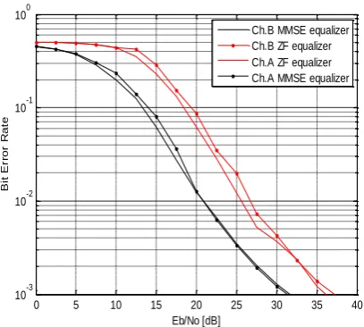
[image:6.595.322.539.78.268.2]Figure (6) shows a comparison in performance between the CPM-OFDM DVB-T system over the two above-mentioned channel models using the ZF equalizer and the MMSE equalizer. The results show that the MMSE equalizer is better than the ZF equalizer in two cases, due to the noise enhancement effect resulting from the ZF equalizer. The results also show the impact of the multi-path diversity on the CPM-OFDM DVB-T system.
Fig.6 Performance of the CPM-OFDM DVB-T system using ZF and MMSE equalizers.
Fig.7A comparison in the performance between the CPM-OFDM DVB –T system,
and the conventional DVB-T system.
Figure (7), shows a comparison in performance between the traditional DVB-T system and the proposed CPM-OFDM DVB-T system in the presence of power amplifier nonlinearities, with IBO = 3 dB, which is the optimum IBO for OFDM systems [14]. The proposed CPM-OFDM DVB-T system outperforms the conventional DVB-T system at high SNR values.
7. CONCLUSIONS
In this paper, a CPM-OFDM DVB-T system has been presented and the performance of this system has been compared with the conventional DVB-T system. The proposedsystem has given a better BER performance than the conventional DVB-T system. The effect of the modulation index on CPM-OFDM DVB-T system has been studied. The simulation experiments have shown that CPM-OFDM DVB-T system exploits the frequency diversity of multi-path channels. So, the proposed CPM-OFDM DVB-T system has given a better performance, a better utilization of the channel frequency diversity, and abetter bandwidth efficiency than the conventional DVB-T system. A trade-off can be made between the BER performance and the bandwidth efficiency in the proposed CPM-OFDM DVB-T system by the appropriate selection of the modulation index value.
REFERENCES
[1] W. Fischer, “Digital video and audio broadcasting technology”, A Practical Engineering Guide, Springer, Third Edition, 2009.
[2] R.V. Nee and R.Prasad, "OFDM for wireless multimedia communications", Artech House: Boston, London, 2000.
[3] H. Schulze and C. Luders, "Theory and application of OFDM and CDMA wideband wireless communication", Wiley, New York, 2005.
[4] P. Banelli, "Theoretical analysis and performance of OFDM signals in nonlinear fading channels", IEEE Transactions on Wireless Communications 2003,
2(2):284–293.
[5] D.Dardari, V.Tralli and A Vaccari, "A theoretical characterization of nonlinear distortion effects in OFDM systems", IEEE Transactions on Communications 2000,
48(10):1755–1764.
0 5 10 15 20 25 30 35 40
10-3 10-2 10-1 100
Eb/No [dB]
B
i
t
E
r
r
o
r
R
a
t
e
Multipath,modulation index=1.1 Multipath,modulation index=0.1 singlepath,modulation index=1.1 singlepath,modulation index=0.1
0 5 10 15 20 25 30 35 40 10-3
10-2 10-1 100
Eb/No [dB]
B
it
E
rr
o
r
R
a
te
Ch.B MMSE equalizer Ch.B ZF equalizer Ch.A ZF equalizer Ch.A MMSE equalizer
0 5 10 15 20 25 30
10-3 10-2 10-1 100
Eb/No dB
B
E
R
[image:6.595.64.268.449.632.2][6] P. Banelli, G. Baruffa,S. Cacopardi. "Effects of HPA non linearity on frequency multiplexed OFDM signals", IEEE Transactions on Broadcasting 2001, 47(2):123–136.
[7] S. Han, J. Lee, "An overview of peak-to-average power ratio reduction techniques for multicarrier transmission", IEEE Transactions on Wireless Communications 2005,
12:56–65.
[8] Y. Lee, Y. You, W. Jeon, J. Paik and H. Song, "Peak-to-average power ratio in MIMO-OFDM systems using selective mapping", IEEE Communications Letters 2003,
7:575–577.
[9] E.S. Hassan, S.E. El-Khamy, M.I. Dessouky, S.A. El-Dolil and F.E. Abd El-Samie, "Peak-to-average power ratio reduction in space–time block coded input multi-output orthogonal frequency division multiplexing systems using a small overhead selective mapping scheme", IET Communications 2009; 3:1667–1674.
[10]H. Chen, H. Liang, "Combined selective mapping and binary cyclic codes for PAPR reduction in OFDM systems", IEEE Transactions on Wireless Communications 2007, 6:3524–3528.
[11] E.S. Hassan, S.E. Khamy, M. I. Dessouky, S.A. El-Dolil and F.E. Abd El-Samie, "A simple selective mapping algorithm for the peak to average power ratio in space time block coded MIMO-OFDM systems", Proceedings of HPCNCS-08, Orlando, FL, U.S.A., July 2008, 103–106.
[12] S. Sengar, P. P. Bhattacharya, "Performance improvement in OFDM system by PAPR reduction", International Journal of Computer Networks & Communications(IJCNC), April 2012.
[13] G. Sikri, Rajni, "Acomparison of different PAPR reduction techniques in OFDM using various modulations" International Journal of Computer Networks & Communications(IJCNC), August 2012.
[14] S.C. Thompson, A.U. Ahmed, J.G. Proakis, J.R. Zeidler, "Constant envelope OFDM phase modulation: spectral containment, signal space properties and performance", Proceedings of IEEE Milcom, vol. 2, Monterey, October 2004, 1129–1135.
[15] M. Kiviranta, A. Mammela, D. Cabric, D.A. Sobel, R.W. Brodersen, "Constant envelope multicarrier modulation performance evaluation in AWGN and fading channels". Proceedings of IEEE Milcom, vol. 2, October 2005, 807– 813.
[16] S.C.Thompson, A.U.Ahmed, "Constant-envelope OFDM", IEEE Transactions on Communications2008,
56:1300–1312.
[17] E.S. Hassan, Xu Zhu, S.E. El-Khamy, M.I. Dessouky, S.A. El-Dolil, F.E. Abd El-Samie,"Performance evaluation of OFDM and single-carrier systems using frequency domain equalization and phase modulation", Int. J. Commun. Syst. 2010.
[18] H. Sari, G. Karam, and I. Jeanclaude, "Transmission techniques for digital terrestrial TV broadcasting, " IEEE Commun. Mag., Feb. 1995.
[19] J. G. Proakis and D. G. Manolakis, "Digital signal processing: principles, algorithms, and applications", 3rd ed. NJ: Prentice Hall, 1996.
[20] J. G. Proakis and M. Salehi, "Communication systems ". New Jersey:Prentice Hall, 1994.
AUTHORS
KhaledRamadanwas born in Menoufia, Egypt, in 1980. He received the B.Sc. degree inelectronics, and electrical communication engineering from Menoufia University, Menoufia,Egypt, in 2002. Currently, he is a Broadcast engineer at ERTU(Egyptian Radio & TV Union), Cairo,
Egypt. His research interests include wireless communications, broadband technologies, and broadcast
communications.
Emad Hassan received the B.Sc. and M.Sc. degrees in ElectricalEngineering from Menoufia University, Egypt in 2003 and 2006, respectively.And Ph.D. from the Faculty of Electronic Engineering, Menoufia University,Menouf, Egypt, He is currently a Lecturer in the Dept.of Electronics and Electrical Communications, Faculty of Electronic Engineering, Menoufia Universit His areas of interests are CDMA, OFDM, SC-FDE, MIMO and CPMbased systems.
Xu Zhu received the B.Eng. degree (with first class honors) from the Huazhong University of Science and Technology, Wuhan, China, in 1999, and the Ph.D. degree from the Hong Kong University of Science and Technology, Hong Kong, in 2003, both in Electrical and Electronic Engineering. Since May 2003, she has been with the Department of Electrical Engineering and Electronics, the University of Liverpool,Liverpool, U.K., where she is currently a lecturer. Dr. Zhu was the vice chair of the 2006 and 2008 ICA Research Network International Workshops, which were held in Liverpool, U.K. She has served as a session chair and atechnical program committee member for various conferences, such as IEEE GLOBECOM 2009 and IEEE VTCSpring-2009. Her research interests include MIMO, OFDM, equalization, blind source separation, cooperative communications and cross-layer optimization, etc.
Mohammed Abd-Elnabyreceived the B.S.(Hons.), M.S., and Ph.D. degrees in electronic engineering from MenoufiaUniversity, Menouf, Egypt in 2000, 2004 and 2010, respectively. Currently, he is working as lecturer at the Department of Electronics and Electrical Communication, Faculty of Electronic Engineering, MenoufiaUniversity, Menouf, Egypt. His research interests include wireless networks, wireless resource management, MAC protocols, cognitive radio, and cooperative communication.
FathiAbd El-Samiereceived the B.Sc. (Honors), M.Sc., and Ph.D. from the Faculty of Electronic Engineering, Menoufia University, Menouf, Egypt, in 1998, 2001, and 2005, respectively. He joined the teaching staff of the Department of Electronics and Electrical Communications,Faculty of Electronic Engineering, Menoufia University, Menouf, Egypt, in 2005. He is a co-author of about 200 papers in national and international conference proceedings and
journals. He has received themost cited paper award from Digital Signal Processing journal for 2008. His current research areas of interest include image enhancement, image restoration, image interpolation, super resolution reconstruction of images, data hiding, multimedia communications, medical image processing, optical signal processing, and digital communications.