Divide and Conquer Steganography Model
V.Raja
S.Rajalakshmi
Research Scholar, Department of Computer Science, Department of Computer Science Bharathiar University, Coimbatore, India. Engineering, SCSVMV University, India
ABSTRACT
Steganography is one of the vital topics in the field of information security. In this paper we propose, a new Steganography algorithm that generates and brings out steganographic secret information hidden in images. In the proposed algorithm, the cover image is partitioned into four non overlapping blocks and the confidential data bits are also divided. The data bits are embedded in scattered way into the four blocks. In each pixel either single colour channel or two colour channels are used to embed the confidential data bits depending upon the size of the data bits. The proposed method generates low MSE value and high PSNR value. The experimental outcome shows, the algorithm can overcome drawbacks of many existing algorithms.
Keyword
- Steganography, MSE, PSNR.1. INTRODUCTION
In the current world, high level protection is required to secure confidential messages at the time of transmission. Today we have two methods, namely cryptography and steganography. Cryptography is the procedure of encoding the secret message which will be decoded only by the right person with the right key. Steganography [1]-[4],[28]-[34] is the method which hides the secret message into cover medium and after embedding secret message the cover medium has a minimal change which is not noticeable by the human eye[6],[8]. Steganography has been used to secretly communicate the information between people in the recent historical times and the present days. Steganography is implemented computationally, with covering medium as text, audio, image or video files used to embed the secret message. Therefore the generic description of steganography process is Cover medium + Secret message + Stego Key = Stego_medium. The resultant files in stego_medium will be of same type of file as cover medium. This paper focuses on image files as cover medium.
1.1 Image Steganography Techniques
Coding secret message in digital image is by far the most widely used of all methods in digital world of today. Many image steganography methods are proposed during the last three years. Out of these algorithms most of them use the substitution methods [8]-[10]. Before entering into these algorithms, images and its architecture are analyzed and then the compression methods on image file and color pattern of Image file are studied [27].Gray scale images are preferred because the shades change very gradually from byte to byte, and the value changes are less between palate entries. They can hide information better when dealing with 8 bit image. The information can be hidden in many ways in images. To hide information, secret message insertion may encode every bit of information in the image or selectively embed the message in noisy areas, which draw less attention [15], [23]; those areas where there is great deal of natural color variation. The message may also be scattered
randomly throughout the image. Redundant pattern encoding wallpapers are used as the cover image with the message. Number of ways exists to hide the information in digital image. The common approaches are
1.2 LSB Image Steganography
The LSB method encoding is by far the most popular of coding techniques [8]-[10], [12]-[14], [16] used for digital images. By using LSB of each byte (8 bits) in an image for a secret message, one can store three bits of data in each pixel for 24 bit images and 1 bit in each pixel for 8 bit images. More information can be stored in a 24 bit image file. For example a grid of 3 pixels of a 24 bit image can be as follows:
00100100 00011000 00011101
01010101 11001010 11100011
11100011 00010100 10001000
78 in binary 1001110 are embedded into the LSB of this part of the image.
00100101 00011000 00011100
01010101 11001011 11100011
11100010 00010100 10001000
On an average only half of the bits in the image will need to be changed according to the embedded message. Using this method we can embed more data in a single image file. Masking & Filtering Image Steganography techniques are very popular for a digital encoding such as digital water masking with lossy compression techniques. The technique also extends image data by masking the secret data over the original data as opposed to hiding information inside the data. The beauty of this masking and filtering technique are that they are immune to image manipulation which makes them very robust.
1.3 Transform Domain Techniques
We have seen that LSB modification techniques are easy ways to embed information, but they are highly vulnerable to even small cover modifications. An attacker can simply apply signal processing techniques in order to destroy the secret information entirely. In many cases even the small changes resulting out of lossy compression systems yield to total information loss. It has been noted early in the development of steganography systems that embedding information in the frequency domain of a signal can be much more robust than embedding rules operating in the time domain. Most robust steganography systems known today actually operate in some sort of transform domain.
transforms. Transformations can be applied over the entire image, to blocks throughout the image, or other variations. However, a trade-off exists between the amount of information added to the image and the robustness obtained. Many transform domain methods are independent to image format and may survive conversion between lossless and lossy formats.
This paper is organized as follows. Section II describes the related work. The proposed algorithm is given in section III. In this section data embedding and data recover algorithms are described. Section IV explains the experimental results and is compared with existing methods. We give a justification of the proposed method. Finally we end the paper with some concluding remarks.
2. RELATED WORK
R.Amirtharaj [7] has proposed the adaptive random k-bit embedding scheme using four different cover images with pixel rate of 256x256. The cover images were divided into 1024 blocks of 8x8 pixels. The confidential message was encrypted and by using raster scan [2],[6],[11],[16],[17],[20],[35],[36] four random scan paths [2],[18],[19],[31],[37] (Z scan SFC, Hilbert SFC, Zigzag SFC, Moore SFC ) message were embedded. The path which results least MSE and Maximum PSNR has been found for each block.
A random pattern key 00,01,10,11 was allotted to four random paths and a particular key was provided to each block thereby all the blocks has a particular key to attain the total embedding capacity. The total key size is found to be 2048 = ((256 x 256) / (8 x 8) )x2 for 8 x 8 blocks and the same procedure has been done for block size 4x4 pixels as well. Therefore, for k=1 bit embedding, 65536 bits can be embedded. For k=2 bits, 3 bits and 4 bits per pixel embedding, the maximum number of possible bits are 131072, 196608 and 262144 respectively.
The maximum capacity limit varies on the basis of total number of key bits to be embedded along with the confidential data. For k=4 embedding , the key occupies 0.98% of the total number of pixels of cover image, and the rest 99.02% was occupied by the confidential data. SFC [5],[11] was chosen to hide the data in cover since it has an unpredictable traverse path through the image. In General, a key is needed in the receiver end to retrieve the data; to avoid and overcome this drawback SFC is adopted.
In the Adaptive Random (AR) k-bit embedding the quality of stego image was estimated initially by adapting Zscan SFC, Hilbert SFC, Zigzag SFC, Moore SFC individually for all 8x8 blocks of a cover image. To prove that the quality of the cover image produced by the AR process has been enhanced, the obtained MSE and PSNR values of the image are compared with results of Individual random traversing path approaches and thus the quality of the AR process stego image does enhanced.
The AR approach has better MSE and PSNR values than the Individual random traversing [2] path approaches and this is possible due to the adaptive selection of a particular random traversing path for every block. The cover image had 1024 blocks of 8x8 pixels in total and thus the required key size would be 2048 bits. The same procedure was adopted for 4x4 pixels but the key size would be 8192 bits respectively.
Additionally, an Adaptive Random Inverted Pattern (ARIP) [14] method had also been implemented in cover images, in order to check whether the quality has enhanced or not. The obtained results were compared with the results of Optimal Pixel Adjustment Process [16] (OPAP) and Inverted Pattern [25] (IP) approaches.
Both the confidential data and key are included in maximum embedding capacity of ARIP. Since the key is embedded in same cover it takes 0.98% of pixels from the total but it can be avoided by sending the key through the key distribution system instead of using regular procedure.
Even though the Adaptive Random (AR) approach has high security level, the obtained PSNR value is still lesser than the values estimated in IP approach. Therefore IP and AR approach are combined to form ARIP approach and the estimated PSNR and MSE values are more satisfactory and better than the values obtained from simple IP and OPAP approaches. In case of 4x4 the performance is further increased by increasing key size. In ARIP approach the required key size which is 3 bits per 8x8 blocks, where 2 bits for selected random traversing path and 1 for IP [14] approach and thus the total key size is 3072 bits and therefore the ARIP approach showed dominance over other approaches.
For achieving maximum embedding capacity a different confidential text has been concerned with different keys in Data Encryption Standard[38] and size of actual confidential message is 8192 characters and they can be pure text, pure number, mixture of text and number and pseudo random inputs. Based on the results generated for each of those cases, PSNR and MSE values are found and the best random path is selected and due to random input the key changes for some covers that increase the security level.
An algorithm has been used to select 8x8 or 4x4 blocks of cover in random order using Pseudo-Random Noise Generator (PRNG). The values of SFC and the starting point changes as soon as the first part of encoded confidential data was embedded in. Thus it eliminates the bias between image and confidential data and this process doesn’t alter the nature of embedded data but alters the embedded path and size of key concerning the retrieval.
3. PROPOSED METHOD
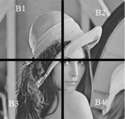
In the proposed scheme a cover image is considered. The cover image is divided into four non overlapping equal size blocks namely B1, B2, B3, and B4 respectively. The confidential message is encrypted using Data Encryption Standard (DES) and it is converted into equivalent binary sequence. The length of the binary sequence depends upon the confidential data size.
is embedded in G&B respectively. Since the data is located in a scattered way in each block, it increases the security level as well as high capacity [21], [22]. In general LSB algorithm, three colour palettes are used but in this proposed method only two colours are used thus it decreases the distraction in the image.
Before the transmission of image the sender generates a key file which would contain confidential data binary sequence length and size of the image. The content of the key file is encrypted using DES algorithm and then it is sent through Key Distribution Center [32] (KDC) along with the image.
On the other hand, the receiver receives the key file and decrypts using DES algorithm, and obtains the message length & image size. After the decryption process, the receiver will verify the size of the image whether it is same as that was specified in image file. If it is false, the receiver would know that the data has been hacked by someone, otherwise the receiver will initiate the reconstruction process. Then receiver collects the data from the image file in the same manner, as it was embedded. Now message is arranged in correct order. Then it will be decrypted using DES. Now the receiver will get the original message.
3.1Data Embedding
Input
1. Cover image 2. Confidential message Output
1. Stego image 2. Key file Algorithm
1. Encrypt the confidential data using DES and convert into binary bits. L= Length of the binary bits.
2. Divide the cover image into 4 equal non overlapping (128 x 128) blocks. These blocks are named as B1, B2, B3 and B4 respectively. 3. Let H = CoverImageHeight
4. Let W = CoverImageWidth
5. // Steps For Embedding the DataBits in Block1 6. Let Cnt = 0;
7. // Counter Variable for Each Block 8. for R = 1 to H/2 do
9. // R is a Row Control Variable in Each Block 10. { for C = 1 to W/2 do
11. // C is a Column Control Variable in Each //Block
12. { for CP = 1 to 2 do
13. // CP is a ColourPalate Control Variable in //Each Block
14. { Call EmbedProcedure(R,C,CP); 15. }}}
16. // similarly Block2,Block3,Block4 will embed //the binary bits of confidential data
17. Repeat step 6 to 15 till BinaryBits End 18. EmbedProcedure( R , C, CP)
{ Pix = CoverImage(R, C, CP); // Obtain the Pixel Value from Coverimage
LSB(Pix) = BitData(Cnt,Cnt+1); // 2BitsfromConfidentialData
Cnt = Cnt + 8;
// Next 6 bits has to be Embed the following //Three Blocks
}
19. Calculate SizeofImage = H * W 20. Calculate MSE Value
21. Calculate PSNR Value
22. Create the Keyfile which Contain SizeofImage,L
23. Transmit the StegoImage and KeyFile.
3.2 Data Recovery
Input
1. Stego image
2. Key file Output
1. Confidential message Algorithm
1. Decrypt the content of the key file using DES algorithm
2. Now receiver obtain the length of binary bits, and size of original image
3. If size != stegoimagesize Return // Stop the process Else
4. Let H = CoverImageHeight 5. Let W = CoverImageWidth 6. // Steps For DataRecovery in Block1 7. Let Cnt =0;
8. for R = 1 to H/2 do
9. // R is a Row Control Variable in Each Block 10. {for C = 1 to W/2 do
11. // C is a Column Control Variable in Each //Block
12. {for CP = 1 to 2 do
13. // CP is a ColourPalate Control Variable in //Each Block
14. { Call DataRecoveryProcedure(R,C,CP); 15. }}}
16. // similarly Block2,Block3,Block4 will recover //the binary bits
17. Repeat step 4 to 15 until binary bit length 18. Procedure DataRecoveryProcedure(R,C,CP)
{ Pix = image(R, C, CP) // obtain the pixel value
Msgbit =bitdata(Cnt,Cnt+1) = LSB (Pix) // Cnt pick the last two bit data
Cnt = Cnt + 8; }
Figure 1. Lena 256x256 Gray (Block B1 – B4)
Position Data
1 0
2 0
3 1
4 1
5 1
6 0
7 0
8 1
9 1
10 0
11 0
….. 1/0
n 1
Table 1. Sample Data
Data embedding in block1.Pix (B1 firstpixel) = (Pixel Red = 77 Pixel Green = 77 Pixel Blue = 77); Pix (B1 firstpixel’s Red) = 77 Binary value for 77 = 1001101; Embed the data (0th and 1st bits from sample data) = 1001101 become 1001100
(76);Pix (B1 firstpixel’s R) becomes 76;Cnt will be increment by 8 // next 6 bits has to be embed the following three block. Pix (B1 firstpixel’s G) = 77 Binary value for 77 = 1001101; Embed the data (8th and 9th bits from sample data) = 1001101
become 1001110 (78);Pix(B1 firstpixel’s G) becomes 78 ;Finally we obtain Pixel Red = 76 Pixel Green = 78 Pixel Blue = 77;Likely all Binarybits will be embed in each Blocks.This cycle will execute till the length of the binary bits.
Data recovery in block1.Pix (B1 firstpixel) = (Pixel Red = 76 Pixel Green = 78 Pixel Blue = 77) ; Pix (B1 firstpixel’s Red) = 76 Binary value for 76 = 1001100;Recover the data from the Last two bits = 1001100 Msgbit= ‘00’;Cnt will be increment by 8 // next 6 bits has to be embed the following three blocks. Pix (B1 firstpixel’s G) = 78 Binary value for 78 = 1001110; Recover the Data from the Last Two Bits = 1001110 Msgbit = ‘0010’; Likely all Binary bits will be recovering from each Blocks. This cycle will execute till the length of the binary bits. Finally we obtain all Msgbit. Arrange the Msgbit in sequential order. Decrypt the Msgbit using DES Algorithm. Receiver gets the original confidential message.
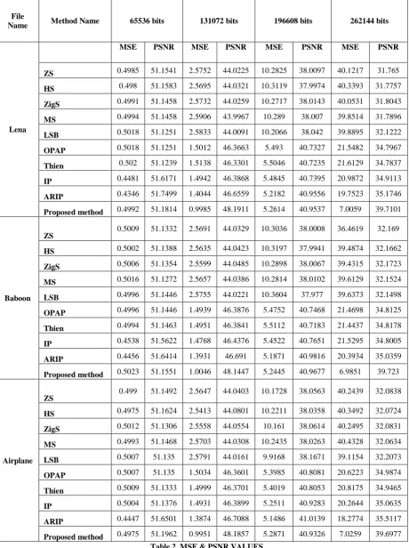
4. RESULT
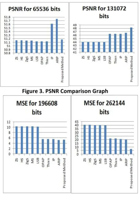
The proposed method has been implemented in three different cover images. The quality of the stego image has been calculated using MSE formula and PSNR formula. The values are listed in Table 2. Stego Image quality is compared with Table1 from [7] four different types scan methods are used namely Zscan SFC, Hillbert SFC, Zigzag SFC , Moore SFC , Adaptive Random and different method of embedding values to be considered, they are LSB, OPAP, [14],[16],[17] Then, IP and ARIP.
These values are taken into account when the image is split only 8x8, because it produces good result compared with image split by 4x4. In the proposed method were the data size is 65536, 131072 one bit data will be embedded into one colour palate. In the rest of the two sizes of data, two bits are embedded into two selected pixels in the colour palate. Thus the proposed method shows a good result, when the data size is 131072bits and 262144 bits. But if the data size is 6553bits or 196608 bits, then the proposed method produces the nearest value to the IP and ARIP. When confidential data bits are embedded into image, either one or two primary colour palates are used. It may be either red, green or green, blue combinations. In every pixel one colour palate is left as it is. It will help to decrease the distraction of the image, so it produce less MSE value and higher PSNR value compared to the other methods in Table 2[7].
File
Name Method Name 65536 bits 131072 bits 196608 bits 262144 bits
Lena
MSE PSNR MSE PSNR MSE PSNR MSE PSNR
ZS 0.4985 51.1541 2.5752 44.0225 10.2825 38.0097 40.1217 31.765
HS 0.498 51.1583 2.5695 44.0321 10.3119 37.9974 40.3393 31.7757
ZigS 0.4991 51.1458 2.5732 44.0259 10.2717 38.0143 40.0531 31.8043
MS 0.4994 51.1458 2.5906 43.9967 10.289 38.007 39.8514 31.7896
LSB 0.5018 51.1251 2.5833 44.0091 10.2066 38.042 39.8895 32.1222
OPAP 0.5018 51.1251 1.5012 46.3663 5.493 40.7327 21.5482 34.7967
Thien 0.502 51.1239 1.5138 46.3301 5.5046 40.7235 21.6129 34.7837
IP 0.4481 51.6171 1.4942 46.3868 5.4845 40.7395 20.9872 34.9113
ARIP 0.4346 51.7499 1.4044 46.6559 5.2182 40.9556 19.7523 35.1746
Proposed method 0.4992 51.1814 0.9985 48.1911 5.2614 40.9537 7.0059 39.7101
Baboon
ZS 0.5009 51.1332 2.5691 44.0329 10.3036 38.0008 36.4619 32.169
HS 0.5002 51.1388 2.5635 44.0423 10.3197 37.9941 39.4874 32.1662
ZigS 0.5006 51.1354 2.5599 44.0485 10.2898 38.0067 39.4315 32.1723
MS 0.5016 51.1272 2.5657 44.0386 10.2814 38.0102 39.6129 32.1524
LSB 0.4996 51.1446 2.5755 44.0221 10.3604 37.977 39.6373 32.1498
OPAP 0.4996 51.1446 1.4939 46.3876 5.4752 40.7468 21.4698 34.8125
Thien 0.4994 51.1463 1.4951 46.3841 5.5112 40.7183 21.4437 34.8178
IP 0.4538 51.5622 1.4768 46.4376 5.4522 40.7651 21.5295 34.8005
ARIP 0.4456 51.6414 1.3931 46.691 5.1871 40.9816 20.3934 35.0359
Proposed method 0.5023 51.1551 1.0046 48.1447 5.2445 40.9677 6.9851 39.723
Airplane
ZS 0.499 51.1492 2.5647 44.0403 10.1728 38.0563 40.2439 32.0838
HS 0.4975 51.1624 2.5413 44.0801 10.2211 38.0358 40.3492 32.0724
ZigS 0.5012 51.1306 2.5558 44.0554 10.161 38.0614 40.2495 32.0831
MS 0.4993 51.1468 2.5703 44.0308 10.2435 38.0263 40.4328 32.0634
LSB 0.5007 51.135 2.5791 44.0161 9.9168 38.1671 39.1154 32.2073
OPAP 0.5007 51.135 1.5034 46.3601 5.3985 40.8081 20.6223 34.9874
Thien 0.5009 51.1333 1.4999 46.3701 5.4019 40.8053 20.8175 34.9465
IP 0.5004 51.1376 1.4931 46.3899 5.2511 40.9283 20.2644 35.0635
ARIP 0.4447 51.6501 1.3874 46.7088 5.1486 41.0139 18.2774 35.5117
[image:5.595.70.531.73.690.2]Proposed method 0.4975 51.1962 0.9951 48.1857 5.2871 40.9326 7.0259 39.6977
Figure 3. PSNR Comparison Graph
Figure 4. MSE Comparison Graph
Hence same function can be used for true colour image instants of gray level images. The confidential data are scattered in the image pixel’s primary colour palate and it will help to give the security to the data. In ARIP, AR method in the related work paper, the size of the key file in [7] is very lengthy when compared with this proposed method. The data set will be created by the random number generator and embedded as well as recovered from the image successfully. The proposed method is implemented in MATAB R 2010a version.
5. CONCLUSION
The proposed method produces high PSNR and low MSE values than the other methods, it depicts that the difference between the original cover image and stego cover image is very less. The proposed method embeds the confidential data in the scattered way in four blocks, so hackers can’t identify the data in sequential order. Two different types of embedding procedure are used. Before embedding, the confidential data is encrypted using Data Encryption Standard. The receiver can identify whether the stego image has to be resized or not, through the Key file. The content of the Key file is also encrypted using the DES algorithm. In table2, the proposed method produces good result at data size (131072, 262144), however in the two cases (65536, 196608) it produces values in the neighborhood of the ARIP method, and hence the proposed method is better than the existing method considered.
6. REFERENCES
[1] Rabah Kefa, “Steganography-The Art of Hiding Data”, Information Technology Journal 3 (3), 2004, 245-269.
[2] N. Provos, P. Honeyman, “Hide and seek: an introduction to Steganography”, IEEE Security & Privacy Magazine 1 ,2003,32–44.
[3] W. Bender, W. Butera, D. Gruhl, R. Hwang, F.J. Paiz, S. Pogreb, “Applications for data hiding”, IBM Systems Journal 39 (3&4) ,2000, 547–568.
[4] Mehdi Kharrazi, Husrev T. Sencar, and Nasir Memon, “Image Steganography: Concepts and Practice” ,WSPC/Lecture Notes Series, 2004.
[5] Hans Sagan, “Space-Filling Curves”, Springer-Verlag, New York, 1994.
[6] W. Bender, D. Gruhl, N. Morimoto, “A. Lu, Techniques for data hiding”, IBM Systems Journal 35 (3&4) ,1996, 313–336.
[7] R.Amitharajan,J.B.BalaguruRayappan , “An intelligent chaotic embedding approach to enhance stego-image quality”, information science Volume 193, 2012, Pages 115–124.
[8] B.Karthikeyan,S.Ramakrishnan,V.Vaithiyanat han,S.Sruti,M.Gomathymeenakshi,”An Improved Steganographic Technique Using LSB Replacement on a Scanned Path Image”, International Journal of Network Security, 15(1), 2013, 314-318.
[9] V. Tyagi, A. Kumar, R. Patel, S. Tyagi, S. S. Gangwar,”Image Steganography using Least Significant Bit with Cryptography”, Journal of Global Research in Computer Science, 3(3), 2012, 53-55.
[10] V. Reddy, A. Subramanyam and P. Reddy, “Implementation of LSB steganography and it's evaluation for various file formats", International Journal of Advanced Networking & Applications, 2011,vol. 2, no. 5, 868-872.
[11] A. Westfeld E.J. Delp, III, P.W. Wong (Eds), “Space filling curves in steganalysis, in Security, Steganography and Watermarking of Multimedia Contents”, VII SPIE 5681, 2005, pp. 28–37.
[12] N. Tiwari, M. Shandilya, “Evaluation of Various LSB based Methods of Image Steganography on GIF File Format”, International Journal of Computer Applications, 6(2), 2010, 1-4.
[13] H.B.Kekre, Archana Athawale and Pallavi N.Halarnkarg, “Increased Capacity of Information Hiding in LSB’s Method for Text and Image”, International Journal of Electrical, Computer and Systems Engineering, 2008, pp.246-249.
[14] C.H. Yang, “Inverted pattern approach to improve image quality of information hiding by LSB substitution”, Pattern Recognition 41 2008, 2674–2683.
[16] C.K. Chan, L.M. Chen, “Hiding data in images by simple LSB substitution”, Pattern Recognition 37 (3) 2004,469–474.
[17] C.C. Thien, J.C. Lin, “A simple and high-hiding capacity method for high-hiding digit-by-digit data in images based on modulus function”, Pattern Recognition 36 (11) ,2003, 2875–2881.
[18] C.C. Chang, T.S. Chen, L.Z. Chung, “A steganographic method based upon JPEG and quantization table modification”, Information Sciences 141, 2002, 123–138.
[19] Chin-Chen Chang, Pei-Yan Pai, Chia-Ming Yeh, Yung-Kuan Chan, “A high payload frequency-based reversible image hiding method”, Information Sciences 180,2010, 2286–2298.
[20] Chin-Chen Chang, The Duc Kieu, “A reversible data hiding scheme using complementary embedding strategy”, Information Sciences 180 ,2010, 3045– 3058.
[21] F. Zhang, Z. Pan, K. Cao, F. Zheng, F. Wu, “The upper and lower bounds of the information-hiding capacity of digital images”, Information Sciences 178 (14–15),2008, 2950–2959.
[22] Tse-Hua Lan and Ahmed H. Tewfik, “A Novel High-Capacity Data-Embedding System”, IEEE Transactions on Image Processing, Vol.15, 2006, pp.2431-2440.
[23] Young-Ran Park, Hyun-Ho Kang, Sang-Uk Shin, Ki-Ryong Kwon, “An image steganography using pixel characteristics”, CIS 2005, Part II, LNAI, vol. 3802, Springer-Verlag, Berlin Heidelberg, 2005, pp. 581–588.
[24] M. Singh, R. Sharma, D. Garg, “A New Purposed Issue for Secure Image Steganography Technique Based On 2-D Block DCT and DCT”, International Journal of Advanced Research in Computer Science and Software Engineering, 2(7), 2012, 29-34.
[25] Po-Yueh Chen, Hung-Ju Lin, “A DWT based approach for image Steganography”, International Journal of Applied Science and Engineering ,2006, 275– 290.
[26] Tolba, M.F.; Ghonemy, M.A.-S.; Taha, I.A.-H.; Khalifa,A.S., “High Capacity Image Steganography using Wavelet-Based Fusion“,Computers and Communications, 2004. Proceedings, ISCC 2004. Ninth International Symposium on Volume, Issue, 28 June-1 July 2004 ,Vol.1, 430-435.
[27] R. González and R. Woods, “Digital image processing”, 2008, Prentice Hall.
[28] Owens, M., “A discussion of covert channels and Steganography”, SANS Institute, 2002.
[29] Silman, J., “Steganography and Steganalysis: An Overview”, SANS Institute, 2001.
[30] Johnson, N.F. and S. Jajodia, “Exploring steganography: Seeing the unseen”, IEEE Computer, 31, 1998, 26-34.
[31] Tuomas Aura, “Practical invisibility in digital communication”, Proceedings of the Workshop on Information Hiding, LNCS 1174, 1996, pp. 265–278.
[32] Bruice Schneier, “Applied Cryptography Protocols”, second ed., Algorithm and Source Code in C, Wiley India Edition, 2007.
[33] Stefan Katzenbeisser, Fabien A.P. Petitcolas:, “Information Hiding Techniques for Steganography and Digital Watermarking”, Artech House,Inc, 2000.
[34] F. A. P. Petitcolas, R. J. Anderson, and M. G. Kuhn, “Information hiding—a survey”, Proc. IEEE, vol. 87, no. 7,1999, pp. 1062–1078.
[35] W. Bender, W. Butera, D. Gruhl, R. Hwang, F.J. Paiz, S. Pogreb, “Applications for data hiding” , IBM Systems Journal 39 (3&4),2000 547–568.
[36] Xiang-Yang Luo, Dao-Shun Wang, Ping Wang, Fen-Lin Liu, “A review on blind detection for image Steganography”, Signal Processing 88,2008, 2138–2157.
[37] F. Zhang, Z. Pan, K. Cao, F. Zheng, F. Wu, “The upper and lower bounds of the information-hiding capacity of digital images”, Information Sciences 178(14–15),2008, 2950–2959.