Improving Congestion Performance in WSN by using
Enhanced Algorithm
P.S.Raghavendran
Assistant Professor (Senior Grade),
Dept. of EEE Kongu Engineering College,
Perundurai 638 052
R.Asokan,
Ph.D Principal, Kongunadu College ofEngineering, Thottium, Trichy Dt,
Tamil Nadu
V.Praveenkumar
, PG Scholar Dept. of EEE, Kongu Engineering College,Perundurai 638 052
ABSTRACT
Wireless sensor networks (WSNs) have expanded their monitoring and tracking applications in wide areas, such as military, medical, and aerospace fields. Although they are used in many important fields, their performance under harsh conditions still remains to be improved, especially when a WSN experience a congestion, the packets reaching the base station (BS) from the near-by node will be higher when compared with the packets delivered from the far-away node reaching the base station. Since the goal of WSN applications is to monitor the whole designated area, such unfairness is not suitable. In addition, the average latency during congestion is very long, failing to fulfil the data freshness requirement of WSN applications. To improve the performance the mostly FIFO (First-In, First-Out) technique is used. In this Technique packets reaching first will be delivered first and the packets coming from faraway node will reach lately than the nearby node hence they are delivered after delivering the nearby node packets. So during this process packets from faraway nodes will get losed more than the nearby nodes. To further improve the fairness performance, the single queue in each node is divided into multiple weighted sub-queues logically, and the packets in each Sub queue are forwarded based on its weight. By doing so the data receptions from other nodes at the BS get balanced. The simulation is done in Qualnet simulator. Both theoretical analysis and extensive experiments verify the performance improvement of our approach.
Index Terms
Wireless sensor network, Queueing, Latency, Base station, Qualnet.
1.
INTRODUCTION
Wireless sensor networks (WSNs) have been used in monitoring and tracking applications in wide areas, such as civil, military, and aerospace fields. Their performance under critical conditions still remains to be improved though they are used in many fields, specifically when congestion occurs in a WSN. The base station can hardly receive any data from the far-away sensor nodes while it still gets a moderate amount of data from the near-by nodes. The main aim of the WSN applications is to monitor the fairness of the entire network. In addition, the average latency during congestion is very long and it spoils the data freshness requirement of WSN applications. The fairness and latency performance of congested WSNs is very important for WSN applications. To improve the performance during congestion a multi-queue-FIFO (First-In, First-Out) approach is being proposed, instead of the frequently employed single-queue FIFO. The
use of multi-queue will reduce delay and improve the fairness performance in congested WSNs when comparing with the single-queue FIFO. To further enhance the fairness performance, the single queue in each node is divided into multiple weighted sub-queues logically, and forward packets in each sub-queue depending upon its weight. Using multi-queue FIFO, the packets received from all nodes will be the increased. Both theoretical analysis and extensive experiments verify the performance improvement of the proposed approach.
The rest of the paper is designed as follows. Section II describes the related work. Section III proposes single-queue FIFO queuing mechanism in overloaded WSNs and improvement in delay and fairness performance during congestion. Section IV proposes a multi-queue algorithm and proves it fairness advantages over single queue. Simulation results are provided in Section V. The conclusion is summarised in section VI.
2.
RELATED
WORK
Many theories for congested queueing system has been developed. Rashmi Ranjan Rout, Student Member and Soumya K. Ghosh, studies the wireless sensor networks lifetime and also to improve the lifetime of WSN by improving the efficiency of bottleneck in WSN. Movaghar studies two different queueing systems with m different servers [7]. They are either designed in a single queueing system or on star shaped systemand they cannot be applied to congested WSN. Chonggang Wang, Kazem Sohraby studies the congestion control in each network depending upon data arrival time and service time [6]. Jang-Ping Sheu, Li-Jen Chang and Wei-Kai Hu studies the hybrid congestion control protocol to maintain the buffer management and also to control the packet delivery [4]. Sang-Hun Han and Sang Kyu Park studies the channel variation due to the motion of human body and to reduce the channel variation by placing an antenna[2].In addition no method is used to control congestion by means of the queueing mechanism. Hence this paper uses a queueing method that helps to improve the performance degradation during congestion. Since the simulation is done in
technique and also the delay is less in multi queue technique when compared with the single queue technique.
3.
SINGLE
QUEUE
FIFO
In a single queue FIFO the packets reaching first will be delivered first. To know the working procedure of single queue FIFO a simple WSN architecture as shown in Figure 1 is taken as an example.
Fig.1.Tree Node Topology of WSN
Considering the case that the WSN employs FIFO, 3 is the farthest from the BS may never have any data received by the BS. Before getting in to the experiment the service time is set at Ts = 3s, transmitting interval is set as Ti = 1s and the delay time is set Td = 30s. The 3-node WSN is overloaded (because Ts=Ti > 1) and will congest in a short period. Here each parent node will transmits a packet and receives a packet earlier from another node than receiving the forwarding packets from its child. Then at 3s(seconds), node 1 has already produced 3 packets, and its first packet has got served and arrived at the BS, and node 2’s first packet is en-queued at the tail of node 1’s queue. As time goes by all the queues are filled with more and more packets and each forwarded packets is queued at the tail of its parent’s queue. So this makes the packets from faraway node to experience more and more packets before it as it travel near to the base station. The first packet generated by node 3 takes 3s for it to arrive at the queue of node 2, though it takes another 9s for the packets to arrive at node 1’s queue. The packets reaches nide 1 at time 12s, it is enqueued at the tail of the queue as the 12th packet. Then it has to wait another 36s (i.e. 3 _ 12) to be the served by node1. However, since the deadline is 30s, it cannot arrive at the BS in time. As for node 3’s following packets, they will also fail to arrive at the BS because the network will become more congested by the time of their generation and forwarding. As a result the packets from the faraway node 3s will get lose before they reaching the base station. In single Queue only one node can transmit one packet at a time hence all the nodes will remain idle at that time. Hence the single-queue FIFO will experience more delay and packet loss. So the packet loss in FIFO will varies depending upon the location of nodes from the base station.
4.
MULTI
QUEUE
FIFO
The multi queue FIFO technique allows the different nodes to send packets at a same time. Although ultra-traditionally by employing multi queue FIFO in WSN improves the congestion performance well when compared to the single queue technique. Since the real sensor node only has a single queue, the multiple sub-queues are maintained logically and thus it’s easy to implement without extra hardware requirement.
[image:2.595.321.553.74.279.2]
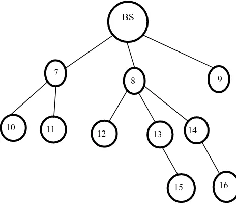
Fig. 2 Tree Topology of WSNs
In order to show the basic mechanism of multi-queue FIFO a tree topology of a WSN is shown in Figure 2.According to FIFO mechanism farther the node is away from the base station, the lower the probability that it packets are received by the base station. In multi-queue mechanism each node is allocated V/N reception capacity and hence it is fairer. In Figure 2, the BS has 3 sub trees rooted at its 3 child nodes, the first sub tree is rooted at node 7 with size 3, the second is rooted at node 8 with size 6, and the third is rooted at node 9 with size 1. Larger sub tree size means more data to be sent to the parent node. When there is no congestion in the network, it is ideal that the child node with larger sub tree will have more data received by the BS. However, in congested situation, since the MAC layer allows fair competition for the channel, the BS will receive almost similar amount of packets from its children. As the reception capacity of the BS is V, then each sub tree is allocated V=3. Thus, each node in sub tree 9 is allocated V=3, each node in sub tree 7 is allocated V=9. In the sub tree 8, node 8, 12, and 13 are allocated V=12, and node 14, 15, and 16 are allocated V=36. This is very unfair to the nodes in sub tree 8.
Our proposed queueing mechanism cannot change the underlying un-fairness caused by unbalanced deployment and routing. For example, node 8 has a larger subtree than the node 7 and 9.However, our multi-queue mechanism can improve the fairness performance by giving overall higher capacity to packets from the larger subtrees, the probability of forwarding packets from children is in proportion with the sizes of the subtrees rooted at the children. In this way, data generated by each node will obtain an equal chance of transmission at the forwarding nodes. For example, the BS allocates its reception capacity V to its children according to their subtree sizes. As a result, subtree 7 is allocated 3V=10, subtree 8 is allocated 6V=10, and subtree 9 is allocated V=10. Finally, each node in all the subtrees is allocated V=10 capacity. It is much fairer than just relying on LIFO or FIFO disciplines. The algorithm consists of a step by step process.
Algorithm 1 Multi-queue-FIFO algorithm at node
ni.
1: calculate Wz, 8z 2 f0; 1; 2; _ _ _ ;Kig. 2: while true. do
3: if node ni finishes the current forwarding. then
BS
3 1 2
BS
7
8 9
10 11
12 13 14
4: remove timeout packets from the queue. 5: if node ni’s queue is not empty. then
6: dequeue a packet from the head of SubQz with probabil- ity Pz; 8z 2 f0; 1; 2; _ _ _ ;Kig.
7: end if 8: end if
9: if a packet arrives at node ni. then 10: remove timeout packets from the queue. 11: if the queue is full. then
12: randomly drop the last packet of a sub-queue. 13: end if
14: enqueue the packet to the head of the queue and updates the corresponding sub-queue.
15: end if 16: end while
By controlling the number of packets to be forwarded for each sub-queue, the fairness is improved. The multi queue-FIFO algorithm at node ni is shown in Algorithm 1.
5.
PERFORMANCE
EVALUATION
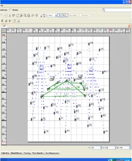
[image:3.595.322.549.101.352.2]The simulation is done by using Qualnet 5.0 as the simulation environment. The performance is carried under different 802.11 MAC layer under AODV routing protocol. The proposed network is designed as a wireless sensor networks which consists of a number of nodes. As shown in the parameter table (Table 1) the environment of the network scenario is created under the dimension of 1500*1500 Meters. Three individual wireless sensor netwoks are placed in the environment and each network has a number of nodes on their own. To initiate the communication between the nodes of different wireless networks the access points are used and without the access points the connection between different nodes of different wireless networks is not possible. The basic design of the network is shown in Fig 3.The nodes are being connected to their respective networks and the network connections toward the access point from the wireless networks are done. In this scenario these fifty nodes are connected through nodes and the nodes are connected through CBR(Constant Bit Rate).The network model shown in Figure 3 is used for both single-queue and multi-queue techniques. Further parameters are designed as shown in the Table 1.
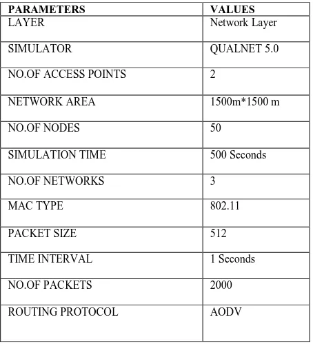
TABLE 1.SIMULATION PARAMETER
The network scenario used for the simulation is shown in Figure 3. The same network is used for single queue and multi queue FIFO and only the channel properties are varied for the simulation. In this scenario three wireless networks are connected through access points and each wireless networks send packets to a node on another network. The transfer of packets takes place in network layer and the protocol used for routing is the AODV. In order to explain the necessary of using 802.11 MAC layer the simulation is also done and it is proved to be the better layer for wireless sensor network. As shown in the figure a number of nodes can be placed within the environment and the connections between the nodes are made in terms of constant bit rate. The Qualnet has a number of components that are capable of performing specified scenario properties. In order to enhance the connections between different wireless networks a access point is used. Here the wireless networks are connected to the access points so that the access point can act as a medium for the transfer of packets between different wireless networks. Without the access point the communication within a home network is possible but the communication from one network to another network is not possible. The transmission of packets are taking place in the network layer and incase if the packets are used in a large amount then a buffer is added in every receiving end of the nodes in order to store the packets and arrange them in queue. The designed network scenario for both queueing techniques is shown in Fig.3.
PARAMETERS VALUES
LAYER Network Layer
SIMULATOR QUALNET 5.0
NO.OF ACCESS POINTS 2
NETWORK AREA 1500m*1500 m
NO.OF NODES 50
SIMULATION TIME 500 Seconds
NO.OF NETWORKS 3
MAC TYPE 802.11
PACKET SIZE 512
TIME INTERVAL 1 Seconds
NO.OF PACKETS 2000
Fig.3 Network Model for Single-queue and Multi-queue
FIFO
A. AODV Routing Protocol
The routing protocol used for the scenario is AODV (Ad-hoc On Demand Distance Vector protocol. The Ad hoc On Demand Distance Vector (AODV) routing algorithm is used for mobile networks AODV can perform both unicast and multicast routing. In AODV, the network will remain silent when a connection is not needed. At a point when a node needs a connection it will broadcast a request for establishing a connection. Other AODV nodes forward this request and record the node that they heard it from. This makes the identification of the needy node easier. Thus the route is provided to the needy node. When a node receives a connection request and already has a route to the desired node, then it sends the message backward through a temporary route to the requesting node. If the number of packets needed to transmit is high then a buffer is used at the receiving nodes to store the packets and to maintain the queue. The advantage of AODV is that it creates no extra traffic for communication along existing links. Also, distance vector routing is simple, and doesn't require much memory or calculation. However AODV requires more time to establish a connection, and the initial communication to establish a route is heavier than some other approaches.
B. Jitter
Jitter is defined as the variation in the time between packets arriving, caused by network congestion. Jitter causes delay in packet delivery. As the number of packets increases the jitter also increases. In mobile communication the jitter causes the crosstalk error and jitter can cause a display monitor to flicker which affects the ability of the processor in a personal
[image:4.595.41.301.72.389.2]computer from performing a intended work. As the jitter level decreases the delay in the packets arrival time can be minimized. So for an efficient network technique the jitter experienced must be low. From the simulated results it is obvious that the packet arrival time in 802.11 multi queue FIFO shows less delay when compared with the single queue FIFO technique.
Fig 4. Jitter Level of Different MAC Layers.
C .Packets Delivery Ratio
Packet delivery ratio is defined as the ratio of the average number of data packets received by the destination node to the number of data packets transmitted by the source node. Selecting a route with less congestion will increase the packet delivery ratio. As the value of packet delivery ratio is higher means the performance of the protocol will be better.
PDR = (1)
Call success ratio is defined as the ratio of number of calls generated by the source to the number of calls accepted by the destination node. The call success ratio is a prime factor used in telecommunication system and also it can be used to detect the number of connected calls in terms of the number of attempts carried on to make a connection. Every time a route is used to forward a data packet and it is said to be a valid route. If the route is unknown or expired then it is considered to be a invalid route.
Success ratio= (2)
[image:4.595.331.501.150.309.2]Fig. 5 Packets Delivery Ratio in Different MAC Layers
D. Throughput Efficiency
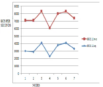
[image:5.595.340.513.70.224.2]Throughput of different MAC layers by using AODV as the routing protocol is simulated. Figure 5.9 shows the variation in throughput for various techniques. From the graph it is clear that 802.11 multi-queue FIFO technique is more efficient in throughput when compared with the 802.11 single queue techniques. The multi-queue technique improves the system fairness more when compared with the single-queue technique and also the delay loss in multi-queue FIFI is less when compared with the single-queue FIFO technique. The increase in sub queues in multi-queue FIFO makes it more efficient than the single-queue FIFO.
Fig. 6 Throughputs of Different MAC Layer
E. End-To-End Delay
It is defined as the average of the time taken by all the multicast packets to reach its destination. First, average delay for packet delivery for each source destination pair is computed. Then the whole average delay is determined from each paired average delay. For congestion less system the end-to-end delay must be low. From the obtained results it is obvious that the multi-queue FIFO shows less end-to-end delay than the single-queue FIFO.
Fig.7. End-to-End-Delay of Different MAC Layers
6.
CONCLUSION
In this paper, to reduce the delay and to improve the fairness performance of congested WSNs the multi-queue-FIFO mechanism is used instead of frequently used single-queue FIFO mechanism. First it is proved that the multi-queue FIFO provides better delay and fairness performance than the single-queue FIFO in congested WSNs. Then to further improve the fairness, it is also implemented a multi-queue algorithm by dividing the real queue of a node into multiple sub-queues and adjusting the serving probability for packets from different sub-queues. Simulation is done by using the Qualnet simulator. On comparing the simulation results of multi-queue-FIFO mechanism with the single-queue FIFO mechanism, it confirms that multi-queue-FIFO reduces delay and improves the fairness performance while maintaining similar throughput better than the single-queue FIFO mechanism.
7.
REFERENCES
[1] Akyildiz, W. Su, Y. Sankarasubramaniam, and E. Cayirci, “A survey on wireless sensor networks,”IEEE Communications Magazine, vol. 40, pp. 102–114, 2002. [2] W.Li and J. Han, “Dynamic wireless sensor network
parameters optimization adapting different node mobility,” in Proc. of the IEEE Aerospace Conference, 2010.
[3] E.Reusens, W.Joseph, G.Vermeeren and J.Martens Ghent University Belgium (2012), “On-Body Measurement and Characterization of Wireless Communication Channel for Arm and Torso of Human”. [4] “Hybrid Congestion Control Protocol in Wireless Sensor Networks” JANG-PING SHEU, LI-JEN CHANG2 AND WEI-KAI HU Department of Computer Science National Tsing Hua University Hsinchu, 300 Taiwan. [5] “An Ultra-Wideband Body Area Propagation Channel
Model—From Statistics to Implementation” Andrew Fort, Student Member, IEEE, Claude Desset, Member, IEEE, Philippe De Doncker,Piet Wambacq, Member, IEEE, and Leo Van Biesen, Member, IEEE.
[image:5.595.85.258.372.518.2][7] “On queueing with customer impatience until the beginning of service,” Queueing Systems Theory and Applications, vol. 29, pp. 337–350, 1998.
[8] L. Schwiebert, S. Gupta, and J. Weinmann, “Research challenges in wireless networks of biomedical sensors,” in Proceedings of the International Conference on Mobile Computing and Networking, 2001, pp. 151-165. [9] Zdarsky, and L. Thiele, “A comprehensive worst-case
calculus for wireless sensor networks with in-network processing,” in Proc. of the IEEE Real-Time Systems Symposium (RTSS), Dec 2007.
[10]“Qualnet 4.5 Network Emulation Interface Model Library” from Scalable Technologies 2008.
[11]Qualnet 5.1 Advanced Model Library” from Scalable Network Technologies September 2012.
[12]O. M. Al-Kofahi and A. E. Kamal, “Network coding-based protection of many-to-one wireless flows,” IEEE J. Sel. Areas Communication., vol. 27,no. 5, pp. 797– 813, 2009.
[13]V. N. Q. Bao, H. Y. Kong, and S. W. Hong, “Performance Analysis of MPAM and M-QAM with Selection Combining in Independent but Non-Identically Distributed Rayleigh Fading Paths,” in Proc. VTC'08, pp. 1-5, Sep. 2008.