R E S E A R C H
Open Access
Wavelet-based color modification detection
based on variance ratio
Jong Ju Jeon and Il Kyu Eom
*Abstract
Color modification is one of the popular image forgery techniques. It can be used to eliminate criminal evidence in various ways, such as modifying the color of a car used in a crime. If the color of a digital image is modified, the locations of the interpolated and original samples may be changed. Because the original and interpolated pixels have different statistical characteristics, these differences can serve as a basic clue for estimating the degree of color modification. It is assumed that the variance of original samples is greater than that of the interpolated samples. Therefore, we present a novel algorithm for color modification estimation using the variance ratio of color difference images in the wavelet domain. The color difference model is used to emphasize the differences between the original and interpolated samples. For color difference images, we execute a wavelet transform and use the highest frequency subband to calculate variances. We define a variance ratio measurement to quantify the level of color modification. Additionally, changed color local regions can be efficiently detected using the proposed algorithm. Experimental results demonstrate that the proposed method generates accurate estimation results for detecting color modification. Compared to the conventional method, our method provides superior color modification detection performance.
Keywords:Color modification, Image forgery, Color difference, Demosaicing, Variance ratio, Wavelet transform, Color filter array
1 Introduction
Using image forgery techniques requires minimal expert-ise because digitized images are easily replicated or manip-ulated. Furthermore, it is difficult to verify the authenticity of images using only the human eye. Therefore, develop-ing reliable image forgery detection methods to determine the authenticity of images has become an important issue [1, 2]. A trace of image manipulations can be used as a clue for detecting altered images. If we can uncover evi-dence indicating image alterations, we can conclude that an image has been forged. There have been several studies on detecting various image forgery techniques, such as copy-move [3–5], image splicing [6–8], scaling [9,10], ro-tation [11], blurring [12, 13], contrast change [14], and color modification [15].
Color modification is one of the commonly used image forgery techniques. It is often exploited to obfus-cate a person by changing their face color, eliminate criminal evidence by modifying the color of a car used
in a crime, or mislead customers by changing the color of a product. Forensic approaches that can detect color modification have not been extensively studied. In 2013, Choi et al. introduced a basic color modification detec-tion method [15]. They defined a color modification at-tack as a change in the ratio between red, blue, and green channels. According to this definition, brightness adjustment, which modifies the luminance of an image, is not a color modification attack. However, hue and white balance adjustments are included in this defin-ition. They designed a color modification detection algo-rithm based on the fact that color filter array (CFA) patterns change if the color of a digital image is modi-fied. They achieved good color modification detection performance using an advanced intermediate value counting (AIVC) algorithm [16]. However, their algo-rithm is only valid for intra-channel demosaicing methods, such as bilinear and bicubic interpolations. Be-cause many demosaicing approaches tend to emphasize high-frequency components by using the correlations between color channels [17–20], the color change detec-tion accuracy of Choi’s algorithm may be reduced. * Correspondence:[email protected]
Department of Electronics Engineering, Pusan National University, 2, Busandaehak-ro 63 beon-gil, Geumjeong-gu, Busan 46241, South Korea
In this paper, we present a novel color modification detection method using the variance ratio in the wavelet domain. For a suspicious image, we first decompose the image into four sub-images. The decomposition process is performed in an even-odd manner in the vertical and horizontal directions. Next, we construct four color dif-ference images in the form of a Bayer CFA pattern: in-terpolated green minus original red, inin-terpolated green minus interpolated red, interpolated green minus ori-ginal blue, and interpolated green minus interpolated blue. For the color difference images, we execute a wave-let transform to extract high-frequency components and then use the highest frequency subband to calculate vari-ances. We define a variance ratio measurement to quan-tify the level of color modification. Through various experiments, we demonstrate that the proposed method generates accurate estimation results for detecting color modification. Compared to the conventional method, our method achieves superior results.
The remainder of this paper is organized as follows: Section 2 describes the color modification detection method based on CFA pattern changes. The proposed color modification detection method and localization algorithm for changed color regions are presented in Section3. Section 4reports the experimental results ob-tained using the proposed approach, and Section5 sum-marizes our conclusions.
2 Estimation of color modification
2.1 Color sample changes through color modification
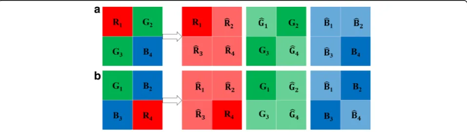
Most commercial image acquisition devices, such as digital cameras, use an inexpensive CFA with a specific shape to acquire color images. The CFA is placed over the image sensor in a digital camera. Each pixel uses only one color from the available choices of red, green, and blue because the image sensor can only measure one color per pixel. Each color channel has missing pixels and requires interpolation. The process of esti-mating missing pixels is referred to as demosaicing. Figure1apresents an example of demosaicing using the
RGGB Bayer pattern [21]. As shown in the left-most 2 × 2 square in Fig. 1a, the red value in the top-left position (R1), green values in the top-right position
(G2 andG3), and blue value in the bottom-right
posi-tion (B4) are all original values. The remaining three
red, two green, and three blue values are interpolated. In the RGGB Bayer pattern, demosaicing is the interpolation process used to estimate fR_2;R
_
3;R
_
4;G
_
1;
G _
4;B
_
1;B
_
2;B
_
3gfrom the original {R1,G2,G3,B4} pattern.
If the colors of an image have been modified, we can observe that the locations of the interpolated pixels and original pixels are changed. Figure 1b presents the color location changes resulting in modifying the hue angle by 120°. In this case, red is changed to green, green is chan-ged to blue, and blue is chanchan-ged to red. The originalR1
in the top-left position is changed to an interpolatedR_1,
while the interpolated R_4 in the bottom-right position is
changed to the originalR4. The other color channels
fol-low a similar pattern. The changed characteristics of color samples are important clues for detecting altered images.
2.2 Conventional color change detection method
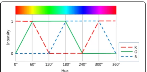
In general, an image generated by the demosaicing process is represented in the RGB color space. Because color modification is related to color information, rather than intensity and saturation, handling images in the hue (H), saturation (S), and intensity (I) color space (HSI color space) is more efficient than handling images in the RGB color space. The hue valueH can be obtained by usingR,G, andBas follows:
H¼ tan−1 ffiffiffi 3 p
G−B
ð Þ
2R−G−B
: ð1Þ
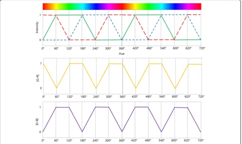
H represents color information as an angle, in the range of H is 0°≤H< 360°. Figure 2 illustrates the rela-tionship between RGB values and hue angles. As shown in Fig. 2, RGB values change in a periodic manner ac-cording to hue changes. If the color of an image is
modified, then the angle of the hue changes. Conversely, a hue change caused by color modification results in an RGB value change.
The conventional algorithm for estimating color modi-fication [15] exploits the color sample changes caused by color modification. This method is based on the idea that the trace of a CFA pattern, which is closely related to color information, changes when the color of an image is modified. If a pixel is interpolated, then its value exists between maximum and minimum values within a pre-defined window with a very high probabil-ity. For a given green sample value G(i,j) at pixel loca-tion (i,j), the maximum value (Gmaxði;jÞ) and minimum value (Gmin
ði;jÞ) within the pre-defined window surrounding G(i,j) are obtained as follows:
Gmaxð Þi;j ¼ max
G kð Þ;l∈W ið Þ;j G kð ;lÞ; ð2Þ
Gminð Þi;j ¼G kð Þ;lmin∈W ið Þ;j G kð ;lÞ; ð3Þ
where W(i,j) is the pre-defined window surrounding
G(i,j). If Gmin
ði;jÞ<Gði;jÞ<Gmaxði;jÞ, thenG(i,j) can be con-sidered as an interpolated green sample. In this case, the count value for interpolated samples is incremented by one. Otherwise, G(i,j) is very likely to be an original sample. In this case, the count value for original samples is incremented by one.
For a given hue angleH, let Ni(H) be the accumulated total count value of interpolated green pixels in the image. Let No(H) be the accumulated total count value of original green pixels. That is, for a givenH,
Nið ÞH ←Nið Þ þH 1; ð Þmini;j <G ið Þ;j <Gmaxð Þi;j
Noð ÞH ←Noð Þ þH 1; otherwise
: ð4Þ
To normalize the total count value, the ratio between two count valuesR(H) is defined as follows: for a given H,R(H) is
R Hð Þ ¼Nið ÞH Noð ÞH :
ð5Þ
If a green sample is an original, then Ni(H) is small and No(H) is large. By rotating the hue angle from 0° to 359°, we can find the hue angle,Hmin for which R(H) is
minimized as follows:
Hmin¼ arg min 0≤H<359 R H
ð Þ: ð6Þ
The shifted hue angle is estimated as follows:
HF ¼360−Hmin ð7Þ
where HF is the altered hue angle. Let us assume that
the modified hue angle is 30°. To estimate the changed hue angle, we can find an angle with minimumR(H) by rotating the angle from 0° to 359°. Assuming an accur-ate estimaccur-ate, the angle with the minimum variance is
Hmin= 330. Therefore, the shifted hue angle is esti-mated as HF= 360−330 = 30. If an image is not
chan-ged, thenHF= 0.
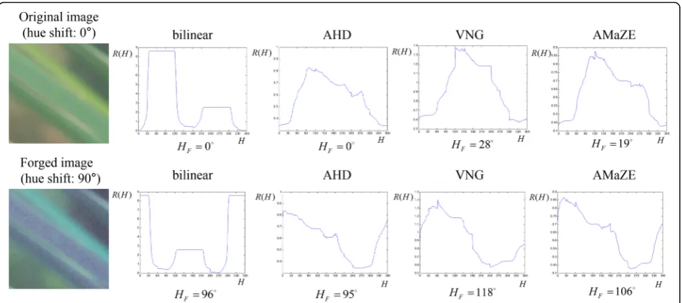
Figure3depicts theR(H) values of an original image (the shifted hue is 0°) and a forged image (the shifted hue is 90°) based on their hue angles. The estimated values ofHFfor various demosaicing methods are pre-sented in Fig.3. We tested four demosaicing methods: bilinear interpolation, the adaptive homogeneity-di-rected (AHD) method [22], variable number of gradients (VNG) algorithm [23], and aliasing mini-mization and zipper elimination (AMaZE) [24]. The demosaiced images are obtained by using the Raw-Therapee [25] tool. As shown in Fig.3, the estimation errors are small for bilinear interpolation, which ex-ploits only the information of its own color channel to interpolate missing color values, because the AIVC method checks the number of pixels outside of the range between the minimum and maximum pixel values.
inter-channel demosaicing method with a color differ-ence model.
3 Proposed method
Basically, an interpolator kernel has the characteristics of a low-pass filter. Therefore, it can be easily deduced that the variance of the original block is larger than that of the interpolated block. Consequently, in the edge re-gions, the original and interpolated pixels have different characteristics. On the contrary, in the background re-gions, these pixels have similar characteristics. There-fore, background regions can have an adverse influence on estimating color modification. The conventional methods employ an inefficient estimation process be-cause they use the same block regardless of the charac-teristics of the image. To remove an adverse influence of background region, we exploit the wavelet transform. Furthermore, to emphasize the effect of high-frequency components, we use the highest frequency subband (HH) in the wavelet domain.
Many demosaicing algorithms employ color differ-ences and attempt to enhance edges. Accordingly, com-mon demosaicing approaches use spectral and spatial correlation for estimating missing pixels using neigh-boring color pixels [26]. Therefore, the majority of color interpolation algorithms are based on the differ-ences between the original sample and filtered sample or between two interpolated samples. Based on this fact, we introduce a novel estimation algorithm for color change detection using color difference images in the wavelet domain. Recently, the variance measure-ment of the color difference model has been success-fully exploited in Bayer CFA pattern identification [27].
Let DGR1 and DGR4 be the color difference images
(green minus red) for an RGGB Bayer CFA pattern, re-spectively. That is,
DGR1 ¼G
_
1−R1; ð8Þ
DGR4 ¼G
_
4−R
_
4: ð9Þ
DGR1 is obtained from the difference between the
in-terpolated green samples and original red samples.DGR4
is calculated from the interpolated green and red sam-ples. We can expect the variance of DGR4 to be smaller
than that ofDGR1. Similarly, we construct two difference
images using green and blue components as follows:
DGB1 ¼G
_
1−B
_
1; ð10Þ
DGB4 ¼G
_
4−B4; ð11Þ
where DGB1 and DGB4 are the color difference images
(green minus blue) for the RGGB Bayer CFA pattern. As shown in (10), DGB1 is calculated by using interpolated
green and blue samples. DGB4 is the difference between
the interpolated green samples and original blue sam-ples. Similar to the case of the differences between the green and red samples, we can assume that the variance ofDGB1 is smaller than that ofDGB4.
Let DWT(X) be the wavelet transform for the image, X, that produces four subbands. Let DCD(H) be the color difference image with hue shift angle H, where CD∈{GR1,GR4,GB1,GB4}. We obtain four
WLL
CDð ÞH WLHCDð ÞH WHLCDð ÞH WHHCDð ÞH
¼DWTðDCDð ÞH Þ;
ð12Þ
whereWLLCDðHÞ,WLHCDðHÞ,WHLCDðHÞ, andWHHCDðHÞ repre-sent four subbands with a hue shift angleHin the wave-let domain. In the wavewave-let transform domain, the highest frequency components exist in the finest fre-quency subband in the diagonal direction. Therefore, the variances of the four difference images in the finest diagonal subband serve as a good measure-ment for detecting color modification. In this paper, we propose two variance ratio measurements using the variances in the diagonal subbands of the color difference images as follows:
VGRð Þ ¼H
σ2 WHH GR4ð ÞH
σ2 WHH GR1ð ÞH
; ð13Þ
VGBð Þ ¼H
σ2 WHH GB1ð ÞH
σ2 WHH GB4ð ÞH
; ð14Þ
where VGR(H) and VGB(H) are the variance ratios for a
given hue angle, H. The denominators in (13) and (14) are obtained from the differences between the fil-tered green samples and original red or blue samples, respectively. The numerators in (13) and (14) are cal-culated from the differences between the two interpo-lated color samples. Therefore, we can expect that the variance ratios will have a smaller value for the original sample. If the image is modified through hue
shifting, the minimum value will occur at the position of the shifted hue angle.
Finally, we define the estimation measurement for de-tecting color modification,VE(H) as follows:
VEð Þ ¼H VGRð Þ þH VGBð ÞH : ð15Þ
To estimate a changed hue angle, the hue of a suspi-cious image is changed from 0° to 359° in increments of a pre-defined interval factor. For eachH,VE(H) is calcu-lated.Hminis the hue angle whereVE(H) yields the mini-mum value, which is written as follows:
Hmin¼ arg min 0≤H<359 VE H
ð Þ: ð16Þ
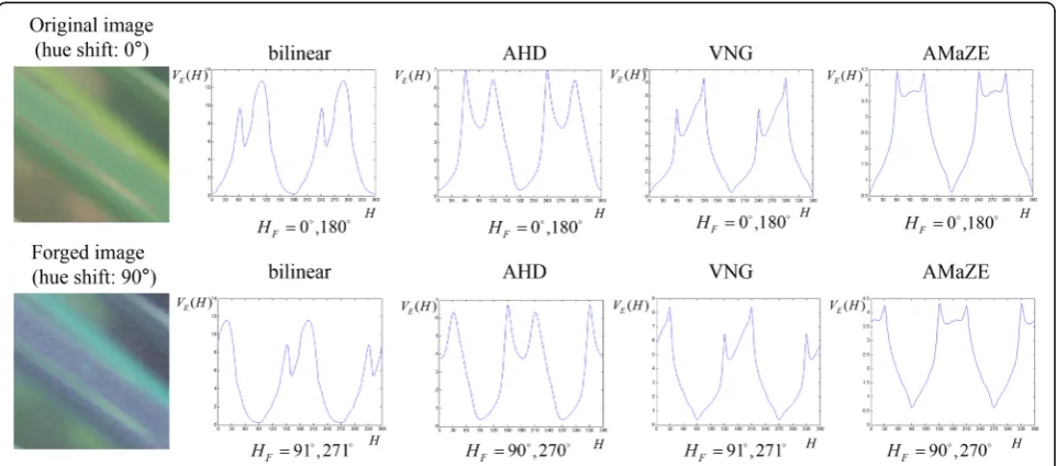
Figure 4 presents the graphs of VE(H) for the hue shifted image and estimated as HF= 360−Hmin. The
test conditions are the same as in Fig. 3. As shown in Fig. 4, the estimation errors obtained by the proposed method are smaller than those obtained by the AIVC algorithm. The average estimation error of the pro-posed method for the eight sample images is 0.25°. The average estimation error of the AIVC algorithm for the eight sample images is 12.75°, as shown in Fig.3. How-ever, we notice that the minimum value occurs twice at Hmin and Hmin+ 180° in our method. This is because
our algorithm is based on the variance of color differ-ence values. The absolute values of color differdiffer-ence have periodicity because blue and red color values are shifted from the green value by 120° and 240°, respect-ively, as shown in Fig. 5. This situation yields conflict-ing results. Because the minimum value occurs twice at HminandHmin+ 180°, we can trace only half of the total
angle range to estimate the exact shifted hue angle.
Therefore, we can cut the estimation time in half based on the periodicity of Hmin. However, we need an
add-itional decision process to determine which of the an-gles is the real shifted hue angle.
In this paper, we introduce the following refinement process to resolve the situation of having two minimum values. The hue value of a suspicious image is changed from 0° to 179° in increments of the pre-defined inter-val factor. The hue angle having the minimum VE(H) value is obtained by changing the hue angle from 0° to 179° as follows:
Hr¼ argmin
0∘≤H≤179∘VE H
ð Þ; ð17Þ
where H
r is the estimated hue angle. We know that
H
r+ 180° is also the minimum angle. To select the
ac-tual minimum value, we use the AIVC algorithm. The angle, H
F from among the minimum values of R(Hr)
and R(H
r+ 180°) can be considered as the real shifted
hue angle. We can determine the final shifted hue angle by using the AIVC algorithm for only the two angles obtained by the proposed method.
The proposed algorithm is summarized in Table 1. As in existing methods, we determine the size of a square image block to estimate the level of color modification and set the hue angle to zero (H= 0). We choose the square image block located at the center of the image and construct four color difference images DGR1, DGR4,
DGB1, and DGB4. For these four difference images, we
Fig. 5The 180° periodicity of the absolute values of color differences
Table 1Summarization of the proposed method
Input: A suspicious image.
Input parameters: Size of a block from the image. Output: Estimated modified hue angleHF.
1) Choose the image block located at the center of the given image. A. SetH= 0.
B. Compute the color differences using (8), (9), (10), and (11). C. Perform the wavelet transform.
D. Calculate the two variances for the highest frequency subbands using (12) and (13)
E. ComputeVE(H) using (15).
F. Increase the hue value byΔH(we useΔH= 5) for the selected image block,
ifH> 360, then go to 2); otherwise, go to B. 2) Find the minimum hue valueHrusing (17) 3) Execute the AIVC algorithm forHrandHr+ 180°. 4) ObtainHFby taking the minimum ofHrandHr+ 180
°
.
Table 2Camera models and image information for the experiments
Camera model Number of images Image size
NIKON D200 728 3904 × 2616
NIKON D70 361 3040 × 2014
perform a discrete wavelet transform and compute the variances of the HH subbands corresponding to the four difference images. We then calculate two variance ratios using (13) and (14). Next, the estimation measurement, VE(H) for detecting color modification is obtained using (15). VE(H) is calculated by repeating the same process until Hbecomes 360°. After obtaining Hrusing (17), we
estimate the modified hue angle HF using the AIVC algorithm.
4 Simulation results
4.1 Test image sets and simulation conditions
In this paper, we used 1460 raw images provided by the Dresden Image Database [28] to evaluate the
Table 3Mean error value comparison between AIVC and the proposed method for various demosaicing methods and shifted hue angles in a 256 × 256 centered block
Demosaicing method Shifted hue degree 0° 45° 90° 135° 180° 225° 270° 315°
Bilinear AIVC 0.02 0.27 0.24 0.24 0.24 0.32 0.34 0.24
Proposed 1.26 1.26 1.26 1.26 1.26 1.26 1.26 1.26
AHD AIVC 12.06 17.42 17.26 17.52 17.94 18.35 18.01 17.62
Proposed 6.26 6.38 6.14 6.38 6.38 6.26 6.14 6.14
AMaZE AIVC 19.66 21.51 21.50 21.65 21.61 21.74 21.78 21.49
Proposed 10.88 11.00 11.00 11.00 11.00 11.00 11.00 11.00
DCB AIVC 22.06 34.26 35.36 36.08 36.76 37.41 35.03 34.20
Proposed 2.23 2.85 2.59 2.85 2.96 2.60 2.72 2.48
LMMSE AIVC 12.24 15.60 15.90 16.27 15.98 16.23 16.09 15.79
Proposed 13.51 13.51 13.51 13.51 13.51 13.51 13.51 13.51
VNG AIVC 8.50 10.71 10.62 10.98 10.76 11.08 10.92 10.61
Proposed 4.95 4.95 4.95 4.95 4.95 4.95 4.95 4.95
HPHD AIVC 30.28 31.55 31.49 31.53 32.06 31.76 31.76 31.75
Proposed 21.87 21.87 21.87 21.87 21.86 21.65 21.76 22.10
Average AIVC 14.97 18.76 18.91 19.18 19.34 19.56 19.13 18.81
Proposed 8.71 8.83 8.76 8.83 8.83 8.75 8.76 8.78
Table 4Mean error value comparison between AIVC and the proposed method for various demosaicing methods and centered blocks with a shifted angle of 45°
Demosaicing method Shifted hue degree 32 × 32 64 × 64 128 × 128 256 × 256 512 × 512
Bilinear AIVC 5.37 2.45 0.79 0.27 0.13
Proposed 2.97 2.01 1.55 1.26 1.29
AHD AIVC 31.50 23.18 19.90 17.42 15.03
Proposed 14.07 9.03 7.30 6.38 5.68
AMaZE AIVC 33.65 26.18 23.22 21.51 17.68
Proposed 21.19 15.12 13.50 11.00 9.85
DCB AIVC 36.26 35.96 35.72 34.26 33.14
Proposed 11.17 6.90 4.40 2.85 1.58
LMMSE AIVC 34.81 24.76 19.42 15.60 12.68
Proposed 34.13 22.40 16.17 13.51 11.84
VNG AIVC 19.28 14.98 12.18 10.71 10.44
Proposed 9.71 7.62 6.49 4.95 5.21
HPHD AIVC 48.95 41.66 36.01 31.55 28.39
Proposed 36.86 26.35 22.07 21.87 20.39
Average AIVC 29.97 24.17 21.04 18.76 16.81
performance of the proposed method. The camera types and detailed information regarding the images used in our experiments are contained in Table2. CFA in-terpolations were performed using RawTherapee [25], which is a well-known cross-platform raw image process-ing program. Seven CFA interpolation algorithms were used in our experiments: bilinear interpolation, AHD interpolation [22], AMaZE interpolation [24], DCB demosaicing [29], linear minimum mean square error (LMMSE) demosaicing [30], VNG algorithm [23], and heterogeneity-projection hard-decision (HPHD) color interpolation [31].
To estimate the shifted hue angles, the center regions of the sample images were cropped into square blocks of
various sizes, such as 512 × 512, 256 × 256, 128 × 128, 64 × 64, and 32 × 32. The hue of the sample images was shifted from 0° to 359° in 45° increments to generate a test image set. In total, 408,800 (1460 × 5 × 8 × 7) test images were generated in our simulations. The mean values of estimation errors, as well as standard devia-tions, were calculated to evaluate the estimation per-formance for altered hue angles.
4.2 Results of color modification detection
Table 3 shows the hue shift estimation performance for the proposed and conventional methods. The mean error values were drawn from the results of the seven demosaicing algorithms, which used a 256 × 256
Table 5Mean error value comparisons between our method and the AIVC algorithm for various hue shift angles
Demosaicing method Shifted hue degree 0° 45° 90° 135° 180° 225° 270° 315°
Bilinear AIVC 1.00 1.80 1.77 1.74 17.74 1.84 1.82 1.71
Proposed 1.82 1.82 1.84 1.84 1.82 1.82 1.82 1.82
AHD AIVC 16.38 21.41 21.41 21.57 21.88 22.40 22.01 21.34
Proposed 8.10 8.49 8.83 8.46 8.46 8.37 8.39 8.30
AMaZE AIVC 22.55 24.48 24.74 24.69 24.61 24.70 24.42 24.20
Proposed 14.17 14.13 14.15 14.02 14.08 14.14 14.12 14.02
DCB AIVC 24.84 35.07 36.00 36.31 37.04 37.38 35.44 34.62
Proposed 4.70 5.38 5.20 5.38 5.34 5.31 5.11 5.17
LMMSE AIVC 18.78 21.45 21.83 21.94 21.93 22.03 21.74 21.40
Proposed 19.48 19.61 19.53 19.58 19.38 19.44 19.32 19.18
VNG AIVC 11.22 13.52 13.67 13.69 13.56 13.90 13.73 13.42
Proposed 6.84 6.80 6.85 6.82 6.79 6.80 6.77 6.82
HPHD AIVC 35.75 37.31 37.34 37.27 37.16 37.23 36.87 37.06
Proposed 25.67 25.51 25.58 25.73 25.54 25.31 25.58 25.37
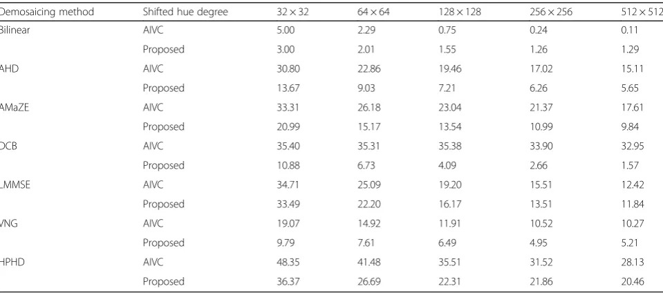
Table 6Mean error value comparisons between our method and the AIVC algorithm for various block sizes
Demosaicing method Shifted hue degree 32 × 32 64 × 64 128 × 128 256 × 256 512 × 512
Bilinear AIVC 5.00 2.29 0.75 0.24 0.11
Proposed 3.00 2.01 1.55 1.26 1.29
AHD AIVC 30.80 22.86 19.46 17.02 15.11
Proposed 13.67 9.03 7.21 6.26 5.65
AMaZE AIVC 33.31 26.18 23.04 21.37 17.61
Proposed 20.99 15.17 13.54 10.99 9.84
DCB AIVC 35.40 35.31 35.38 33.90 32.95
Proposed 10.88 6.73 4.09 2.66 1.57
LMMSE AIVC 34.71 25.09 19.20 15.51 12.42
Proposed 33.49 22.20 16.17 13.51 11.84
VNG AIVC 19.07 14.92 11.91 10.52 10.27
Proposed 9.79 7.61 6.49 4.95 5.21
HPHD AIVC 48.35 41.48 35.51 31.52 28.13
centered block. As shown in Table 3, the mean values of the estimation errors obtained by the proposed al-gorithm are slightly larger than those of the AIVC method in the case of bilinear interpolation. However, our estimation method is superior to the AIVC algo-rithm for AHD, AMaZE, DCB, LMMSE, VNG, and HPHD interpolations. The averaged mean error values achieved by the proposed method for the shifted hue angles ranged from 8.71 (for 0°) to 8.83 (for both 45° and 135°). On the other hand, the averaged mean error values obtained by the AIVC method ranged from 14.87 (for 0°) to 19.56 (for 225°). These results indicate that the AIVC method based on intermediate value counting is only suitable for bilinear interpolation. In summary, our method achieves better estimation per-formance than the AIVC method when considering various demosaicing methods and altered hue angles. In particular, the estimation errors in our algorithm
are nearly independent of the altered hue angles. The AIVC algorithm has superior estimation performance only when image forgeries are not created.
Table4contains the color forgery detection perform-ance results for the proposed and conventional methods. For a shifted hue angle of 45°, the mean error values are calculated based on the various cropped cen-ter block sizes. As shown in Table4, the averaged mean error values of the proposed method for various cropped center block sizes ranged from 7.98 (for a 512 × 512 block) to 18.59 (for a 32 × 32 block). The averaged mean error values obtained by the AIVC method ranged from 16.81 (for a 512 × 512 block) to 29.97 (for a 32 × 32 block). The size of the cropped cen-ter block can affect both estimation performance and computational cost. A larger block size can provide bet-ter estimation performance but suffers from high com-putation time.
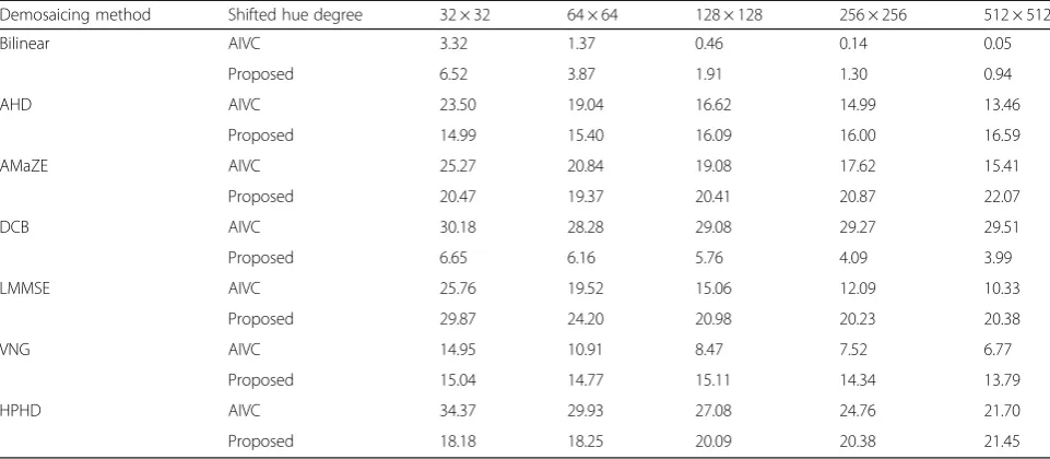
Table 7Mean error value comparisons between our method and the AIVC algorithm after white balancing and gamma correction for various block sizes
Demosaicing method Shifted hue degree 32 × 32 64 × 64 128 × 128 256 × 256 512 × 512
Bilinear AIVC 3.32 1.37 0.46 0.14 0.05
Proposed 6.52 3.87 1.91 1.30 0.94
AHD AIVC 23.50 19.04 16.62 14.99 13.46
Proposed 14.99 15.40 16.09 16.00 16.59
AMaZE AIVC 25.27 20.84 19.08 17.62 15.41
Proposed 20.47 19.37 20.41 20.87 22.07
DCB AIVC 30.18 28.28 29.08 29.27 29.51
Proposed 6.65 6.16 5.76 4.09 3.99
LMMSE AIVC 25.76 19.52 15.06 12.09 10.33
Proposed 29.87 24.20 20.98 20.23 20.38
VNG AIVC 14.95 10.91 8.47 7.52 6.77
Proposed 15.04 14.77 15.11 14.34 13.79
HPHD AIVC 34.37 29.93 27.08 24.76 21.70
Proposed 18.18 18.25 20.09 20.38 21.45
Mean error value comparisons between our method and the AIVC algorithm for various shifted hue angles are presented in Table5. The error values were averaged according to the cropped center block sizes. As shown in Table5, our method achieves superior estimation per-formance compared to the AIVC method, except for bi-linear interpolation. Table6 shows the mean error value comparisons between our method and the AIVC algo-rithm for various block sizes. The error values were averaged from all shifted angles. As shown in Table 6, our color change detection algorithm is superior to the conventional AIVC method, except for the three bilinear interpolation examples that have center block sizes lar-ger than 128 × 128.
In general, images are captured and then used through image pipelines such as white balancing, gamma correc-tion, and noise reduction. In this paper, we also tested our method for white-balanced and gamma-corrected images. For white balancing, we exploited“white patch” algorithm [32]. We used“lin2rgb”function inMatlabto obtain gamma-corrected images. Table 7 shows the mean error value comparisons between our method and the AIVC algorithm after white balancing and gamma correction for various block sizes. As shown in Table7, we can see that the white balancing and gamma correc-tion have some influence on the color forgery deteccorrec-tion. Unlike Table6, the AIVC method shows better detection performance than the proposed algorithm in the bilin-ear interpolation, LMMSE, and VNG demosaicing method. The AIVC algorithm has a positive effect, while the proposed method is negatively affected. It is considered that the white balancing and gamma correc-tion affect the variance, and the performance of the proposed method will be degraded because our algo-rithm is based on the variance. However, the proposed method still achieves better detection results for other demosaicing algorithms.
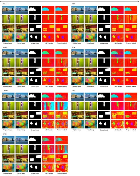
4.3 Forged color region detection
For this paper, we generated four forged color images usingAdobe Photoshop CS4 (64 bit) as shown in Fig. 6. The castle in “sample 1” was altered with a 180° hue shift, and the poster on the door in “sample 2” was shifted by−90°. In“sample 3”, two regions (the fish tank and the pictures on the wall) were altered by −45°. Fi-nally, two countries on the globe in sample 4 were shifted by −45° and 90°. The test sample images were sliced into 32 × 32 blocks. The test was performed by shifting the hue angle in 5° increments. Figure7presents the forged color region detection results for the seven demosaicing methods. For all demosaicing methods, our proposed method outperforms the conventional AIVC algorithm. As shown in Fig. 7, it is hard to estimate color shift angles or detect a forged region using the
AMaZE, LMMSE, VNG, and HPHD demosaicing methods. This indicates that forged color detection still requires significant research.
5 Discussion
The proposed algorithm has a reasonable accuracy in es-timating the level of color modification. The results of the proposed method are superior to those obtained using the conventional method for all demosaicing algo-rithms except bilinear interpolation. In addition, the pro-posed approach can be applicable to localize forged color regions. However, the area of color modification detection still needs a lot of research based on the re-sults of the previous and our studies.
6 Conclusions
In this paper, we presented a new color modification de-tection algorithm using the variance ratio of color differ-ence images in the wavelet domain. We generated a color difference model to emphasize the differences be-tween original pixels and interpolated pixels. We also in-troduced a variance ratio measurement using the highest frequency subband in the wavelet domain to quantify the level of hue angle modification. Experimental results demonstrated that the proposed method generates accur-ate estimation results for detecting color modification. Compared to the conventional method, our method pro-vides superior color modification detection performance. In addition, we verified that modified color regions could be efficiently detected using the proposed algorithm.
Abbreviations
AHD:Adaptive homogeneity-directed; AIVC: Advanced intermediate value counting; AMaZE: Aliasing minimization and zipper elimination; CFA: Color filter array; H: Hue; HPHD: Heterogeneity-projection hard-decision; I: Intensity; LMMSE: Linear minimum mean square error; S: Saturation; VNG: Variable number of gradients
Funding
This research was supported by Basic Science Research Program through the National Research Foundation of Korea (NRF) funded by the Ministry of Education (NRF-2015R1D1A3A01019561), and BK21PLUS, Creative Human Resource Development Program for IT Convergence.
Availability of data and materials Please contact the author for data requests.
Authors’contributions
JJJ proposed the framework of this work, carried out the whole experiments, and drafted the manuscript. IKE initiated the main algorithm of this work, supervised the whole work, and wrote the final manuscript. Both authors read and approved the final manuscript.
Competing interests
Both authors declare that they have no competing interests.
Publisher’s Note
Received: 16 November 2017 Accepted: 29 May 2018
References
1. H Farid, A survey of image forgery detection. IEEE Signal Process. Mag. 2(26), 16–25 (2009)
2. B Mahdian, S Saic, A bibliography on blind methods for identifying image forgery. Signal Process. Image Commun.25(6), 389–399 (2010)
3. B Xiuli, P Chi-Man, Fast reflective offset-guided searching method for copy-move forgery detection. Inf. Sci.418-419, 531–545 (2017)
4. D Cozzolino, G Poggi, L Verdoliva, Efficient dense-field copy–move forgery detection. IEEE Trans. Inf. Forensics Secur.10, 2284–2297 (2015) 5. R Davarzani, K Yaghmaie, S Mozaffari, M Tapak, Copy-move forgery
detection using multiresolution local binary patterns. Forensic Sci. Int. 231, 61–72 (2013)
6. X Zhao, S Wang, S Li, J Li, Passive image-splicing detection by a 2-D noncausal Markov model. IEEE Trans. Circuits Syst. Video Technol.25(2), 185–199 (2015)
7. Z He, W Lu, W Sun, J Huang, Digital image splicing detection based on Markov features in DCT and DWT domain. Pattern Recogn.45(12), 4292–4299 (2012) 8. JG Han, TH Park, YH Moon, IK Eom, Efficient Markov feature extraction
method for image splicing detection using maximization and threshold expansion. J. Electron. Imaging.25(2), 023031 (2016)
9. AC Popescu, H Farid, Exposing digital forgeries by detecting traces of resampling. IEEE Trans. Signal Process.53(2), 758–767 (2005) 10. B Mahdian, S Saic, Blind authentication using periodic properties of
interpolation. IEEE Trans. Inf. Forensics Secur.3(3), 529–538 (2008) 11. W Wei, S Wang, Estimation of image rotation angle using
interpolation-related spectral signatures with application to blind detection of image forgery. IEEE Trans. Inf. Forensics Secur.5(3), 507–517 (2010)
12. G Liu, J Wangb, S Lian, Y Dai, Detect image splicing with artificial blurred boundary. Math. Comput. Model.57, 2647–2659 (2013)
13. G Cao, Y Zhao, R Ni, Edge-based blur metric for tamper detection. J. Inf. Hiding Multimedia Signal Process.1(1), 20–27 (2010)
14. G Cao, Y Zhao, R Ni, X Li, Contrast enhancement-based forensics in digital images. IEEE Trans. Inf. Forensics Secur.9(3), 515–525 (2014)
15. CH Choi, HY Lee, HK Lee, Estimation of color modification in digital images by CFA pattern changes. Forensic Sci. Int.226, 94–105 (2013)
16. CH Choi, JH Choi, HK Lee,CFA pattern identification of digital cameras using intermediate value counting, Proceedings of ACM Workshop in Multimedia and Security (2011), pp. 21–26
17. DR Cok, Signal processing method and apparatus for producing interpolated chrominance values in a sampled color image signal. US Patent 4642678, (1987).
18. WT Freeman, Median filter for reconstructing missing color samples. US Patent 4724395, (1988)
19. CA Laroche, MA Prescott, Apparatus and method for adaptively interpolating a full color image utilizing chrominance gradients. US Patent 5373322, (1994)
20. JF Hamilton, JE Adams, Adaptive color plan interpolation in single sensor color electronic camera. US Patent 5629734, (1997)
21. BE Bayer, Color imaging array. US Patent 3971065, (1976) 22. K Hirakawa, TW Parks, Adaptive homogeneity directed demosaicing
algorithm. IEEE Trans. Image Process.14(3), 360–369 (2005)
23. E Chang, S Cheung, DY Pan,Color filter array recovery using a threshold-based variable number of gradients, Proceedings of SPIE, Sensors, Cameras, and Applications for Digital Photography (1999), pp. 36–43
24. E Martinec, P Lee,AMAZE demosaicing algorithm.http://www.rawtherapee.com/. Accessed 15 June 2017
25. G Horvath,http://www.rawtherapee.com/. Accessed 22 Apr 2017. 26. K HS, SS Kim, IK Eom, Wavelet-domain demosaicking using linear estimation
of interchannel correlation. Opt. Eng.47(6), 067002 (2008)
27. HJ Shin, JJ Jeon, IK Eom, Color filter array pattern identification using variance of color difference image. J. Electron. Imaging.26(4), 0243303015 (2017) 28. T Gloe, R Bohme,The‘Dresden Image Database’for benchmarking digital
image forensics, Proceedings of the 25th Symposium on Applied Computing (2010), pp. 1585–1591
29. J Gozd, DCB demosaicing algorithm.http://www.linuxphoto.org/html/dcb.html. Accessed 15 June 2017
30. L Zhang, X Wu, Color demosaicking via directional linear minimum mean square-error estimation. IEEE Trans. Image Process.14(12), 2167–2178 (2005) 31. CY Tsai, KT Song, Heterogeneity-projection hard-decision color interpolation using spectral-spatial correlation. IEEE Trans. Image Process.16(11), 78–91 (2007) 32. EH Land, JJ McCann, Lightness and retinex theory. J. Opt. Soc. Am.