Section 9.36. Energy Efficiency
9.36.1. General
9.36.1.1. Scope
1) This Section is concerned with the energy used by buildings as a result of a) the design and construction of the building envelope, and
b) the design and construction or specification of systems and equipment for i) heating, ventilating or air-conditioning, and
ii) service water heating. (See AppendixA.) 9.36.1.2. Definitions
1) For the purpose of this Section, the term “common space” shall mean all spaces required to be conditioned spaces in accordance with the requirements of the Code that are not within a suite but shall not include crawl spaces and vertical service spaces. (See A-9.36.1.3.(3) in Appendix A.) 2) For the purpose of this Section, the term “overall thermal transmittance,” or U-value, shall mean the
rate, in W/(m2·K), at which heat is transferred through a building assembly that is subject to
temperature differences. (See AppendixA.)
3) For the purpose of this Section, the term “effective thermal resistance,” or RSI value, shall mean the inverse of the overall thermal transmittance of an assembly, in (m2·K)/W. (See AppendixA.)
4) For the purpose of this Section, the term “fenestration” shall mean all building envelope assemblies, including their frames, that transfer visible light, such as windows, clerestories, skylights, translucent wall panels, glass block assemblies, transoms, sidelights, sliding, overhead or swinging glass doors, and glazed inserts in doors, etc. (See AppendixA.)
9.36.1.3. Compliance and Application (See AppendixA.)
1) Except as provided in Sentences(2) to(5), buildings shall comply with a) the prescriptive or trade-off requirements in Subsections9.36.2. to9.36.4., b) the performance requirements in Subsection9.36.5., or
c) the NECB.
2) Subsections9.36.2. to9.36.4. apply to
a) buildings of residential occupancy to which Part 9 applies,
b) buildings containing business and personal services, mercantile or low-hazard industrial occupancies to which Part 9 applies whose combined total floor area does not exceed 300 m2, excluding parking
garages that serve residential occupancies, and
January 2015 - This PDF is for information purposes only, and does not form the replacement package of the BC Building Code print product. These revisions were effective December 19, 2014 and have been consolidated within the online BC Building Code product.
c) buildings containing a mix of the residential and non-residential occupancies described in Clauses(a) and (b).
3) Subsection9.36.5. applies only to
a) houses with or without a secondary suite, and
b) buildings containing only dwelling units and common spaces whose total floor area does not exceed 20% of the total floor area of the building.
(See AppendixA.)
4) Buildings containing non-residential occupancies whose combined total floor area exceeds 300 m2 or medium-hazard industrial occupancies shall comply with the NECB.
5) Buildings or portions of buildings that are not required to be conditioned spaces are exempted from the requirements of this Section. (See AppendixA.)
9.36.2. Building Envelope
9.36.2.1. Scope and Application1) Except as provided in Sentence(2), this Subsection is concerned with the loss of energy due to heat transfer and air leakage through materials, components and assemblies, including their interfaces, forming part of the building envelope where it separates conditioned space from unconditioned space, the exterior air or the ground.
2) The requirements of this Subsection also apply to components of a building envelope assembly that separate a conditioned space from an adjoining storage garage, even if the storage garage is intended to be heated. (See AppendixA andA-9.36.1.3.(5) in Appendix A.)
3) Except for skylight shafts addressed in Sentence9.36.2.6.(3), for the purpose of this Subsection, wall assemblies inclined less than 60° from the horizontal shall be considered as roof assemblies, and roof assemblies inclined 60° or more from the horizontal shall be considered as wall assemblies.
4) The properties, performance and installation of windows, doors and skylights shall also conform to Section9.7.
5) The properties, location and installation of thermal insulation, air barrier systems, vapour barriers, and materials with low air or vapour permeance shall also conform to Section9.25.
9.36.2.2. Determination of Thermal Characteristics of Materials, Components and Assemblies
1) The thermal characteristics of materials shall be determined by calculation or by testing in accordance with the applicable product standards listed in the Code or, in the absence of such standards or where such standards do not address the determination of thermal resistance, in accordance with
a) ASTM C 177, “Steady-State Heat Flux Measurements and Thermal Transmission Properties by Means of the Guarded-Hot-Plate Apparatus,” or
b) ASTM C 518, “Steady-State Thermal Transmission Properties by Means of the Heat Flow Meter Apparatus.”
(See TableA-9.36.2.4.(1)D. in Appendix A for the thermal characteristics of commonly used materials.) 2) Calculations and tests performed in accordance with Sentence(1) shall be carried out at an average
temperature of 24±2°C and under a temperature differential of 22±2°C.
3) The thermal characteristics of windows, doors and skylights shall be determined by calculation or testing in accordance with
a) CSA A440.2/A440.3, “Fenestration Energy Performance/User Guide to CSA A440.2-09, Fenestration Energy Performance,” for the reference sizes listed therein, or
b) NFRC 100, “Determining Fenestration Product U-factors,” and NFRC 200, “Determining Fenestration Product Solar Heat Gain Coefficient and Visible Transmittance at Normal Incidence,” for the reference sizes listed therein.
(See AppendixA.)
4) The effective thermal resistance of opaque building assemblies shall be determined from a) calculations conforming to Article9.36.2.4., or
b) laboratory tests performed in accordance with ASTM C 1363, “Thermal Performance of Building Materials and Envelope Assemblies by Means of a Hot Box Apparatus,” using an indoor air temperature of 21±1°C and an outdoor air temperature of –35±1°C.
5) The thermal characteristics of log walls shall be determined by calculation in accordance with Section 305 of ICC 400, “Design and Construction of Log Structures.” (See AppendixA.)
9.36.2.3. Calculation of Ceiling, Wall, Fenestration and Door Areas
1) The gross roof-ceiling assembly area shall be calculated as the sum of the interior surface areas of insulated roof-ceiling assemblies and of skylight openings.
2) Except as permitted by Sentence (3), the gross wall area shall be calculated as the sum of the interior surface areas of all exterior building envelope assemblies above the finished ground level that are inclined 60° or more from the horizontal, including
a) rim joists,
b) fenestration and opaque portions of doors,
c) insulated walls extending from finished ground level to the interior side of the insulated roof-ceiling assembly, and
d) the exposed areas of below-ground building envelope assemblies, where fenestration or doors are located below the plane of the adjacent finished ground.
(See AppendixA.)
3) Where a building of residential occupancy contains more than 2 dwelling units, the gross wall area enclosing conditioned space shall be permitted to include the interior surface areas of walls that enclose a suite, measured from the top surface of the lowest floor to the underside of the highest ceiling in the suite. (See AppendixA.)
4) Fenestration and door areas shall be the actual sizes of windows, doors and skylights including all related frame and sash members.
5) The fenestration area made of flat panes that are not all in the same plane or curved panes shall be measured along the surface of the glass. (See AppendixA.)
9.36.2.4. Calculation of Effective Thermal Resistance of Assemblies
1) In calculating the effective thermal resistance of assemblies for the purpose of comparison with the requirements of Articles9.36.2.6. and9.36.2.8., the thermal bridging effect of closely spaced, repetitive structural members, such as studs and joists, and of ancillary members, such as lintels, sills and plates, shall be accounted for. (See AppendixA.)
2) Minor penetrations through assemblies, such as pipes, ducts, equipment with through-the-wall venting, packaged terminal air conditioners or heat pumps, shelf angles, anchors and ties and associated fasteners, and minor structural members that must partially or completely penetrate the building envelope to perform their intended function need not be taken into account in the calculation of the effective thermal resistance of that assembly.
3) Major structural penetrations, such as balcony and canopy slabs, beams, columns and ornamentation or appendages that must completely penetrate the building envelope to perform their intended function, need not be taken into account in the calculation of the effective thermal resistance of the penetrated assembly, provided
a) the insulation is installed tight against the outline of the penetration, and
b) the sum of the areas of all such major structural penetrations is limited to a maximum of 2% of the gross wall area calculated as described in Sentence9.36.2.3.(2).
(See AppendixA.)
4) Where a component of the building envelope is protected by an enclosed unconditioned space, such as a sun porch, enclosed veranda, vestibule or attached garage, the required effective thermal resistance of the building envelope component between the building and the unconditioned enclosure is permitted to be reduced by 0.16 (m2·K)/W. (See AppendixA.)
9.36.2.5. Continuity of Insulation
1) Except as provided in Sentences(2) to(9) and in Sentence9.36.2.4.(3) regarding balcony and canopy slabs, and except for clearances around components required for fire safety reasons, interior building components that meet building envelope components and major structural members that partly penetrate the building envelope shall not break the continuity of the insulation and shall not decrease the effective thermal resistance at their projected area to less than that required in Articles9.36.2.6. and9.36.2.8. (See AppendixA.)
2) Where an interior wall, foundation wall, firewall, party wall or structural element penetrates an exterior wall or insulated roof or ceiling and breaks the continuity of the plane of insulation, the penetrating element shall be insulated
a) on both of its sides, inward or outward from the building envelope, for a distance equal to 4 times its uninsulated thickness to an effective thermal resistance not less than that required for exterior walls as stated in Table9.36.2.6.A. or9.36.2.6.B.,
b) within the plane of insulation of the penetrated element to an effective thermal resistance not less than 60% of that required for the penetrated element, or
c) within itself to an effective thermal resistance not less than that required for the penetrated element. (See AppendixA.)
3) Where a masonry fireplace or flue penetrates an exterior wall and breaks the continuity of the plane of insulation, it shall be insulated within the plane of insulation of the wall or within itself to an effective thermal resistance not less than 55% of that required for the exterior wall as stated in Table9.36.2.6.A. or9.36.2.6.B. (See AppendixA.)
4) Where an ornamentation or appendage penetrates an exterior wall and breaks the continuity of the plane of insulation, the penetrating element shall be insulated
a) on both of its sides, inward or outward from the building envelope, for a distance equal to 4 times the insulated thickness of the exterior wall to an effective thermal resistance not less than that required for the wall as stated in Table9.36.2.6.A. or9.36.2.6.B.,
b) within the plane of insulation of the wall to an effective thermal resistance not less than 55% of that required for the exterior wall, or
c) within the penetrating element to an effective thermal resistance not less than that required for the exterior wall.
5) Except as provided in Sentences(8) and(9), where two planes of insulation are separated by a building envelope assembly and cannot be physically joined, one of the planes of insulation shall be extended for a distance equal to at least 4 times the thickness of the assembly separating the two planes. (See AppendixA.)
6) Where mechanical, plumbing or electrical system components, such as pipes, ducts, conduits, cabinets, chases, panels or recessed heaters, are placed within and parallel to a wall assembly required to be insulated, the effective thermal resistance of that wall at the projected area of the system component shall be not less than that required by Tables9.36.2.6.A.,9.36.2.6.B.,
9.36.2.8.A. and9.36.2.8.B. (See AppendixA.)
7) Except as permitted by Article9.36.2.11., where mechanical ducts, plumbing pipes, conduits for electrical services or communication cables are placed within the insulated portion of a floor or ceiling assembly, the effective thermal resistance of the assembly at the projected area of the ducts, pipes, conduits or cables shall be not less than 2.78 (m2·K)/W.
8) Joints and junctions between walls and other building envelope components shall be insulated in a manner that provides an effective thermal resistance that is no less than the lower of the minimum values required for the respective adjoining components. (See AppendixA.) 9) Sentence(1) does not apply where the continuity of the insulation is interrupted
a) between the insulation in the foundation wall and that of the floor slab,
b) by an integral perimeter footing of a slab-on-grade (see Sentences9.25.2.3.(5) and9.36.2.8.(8)), or c) at the horizontal portion of a foundation wall that supports masonry veneer and is insulated on the
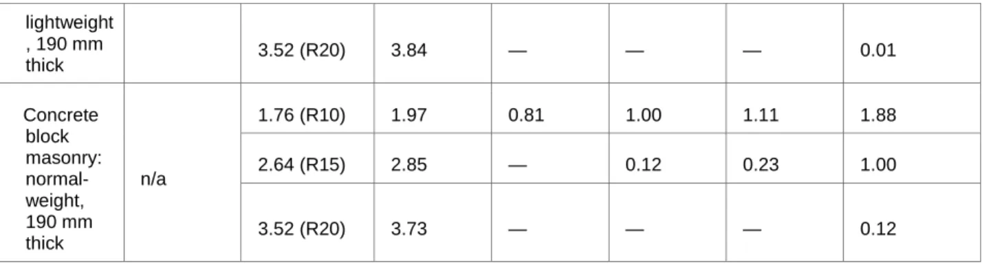
9.36.2.6. Thermal Characteristics of Above-ground Opaque Building Assemblies 1) Except as provided in Sentences(2) and9.36.2.8.(3) and Articles9.36.2.5. and9.36.2.11., the effective
thermal resistance of above-ground opaque building assemblies or portions thereof shall be not less than that shown for the applicable heating degree-day category in
a) Table9.36.2.6.A., where the ventilation system does not include heat-recovery equipment, or b) Table9.36.2.6.B., where the ventilation system includes heat-recovery equipment conforming to
Article9.36.3.9. (See AppendixA.)
Table 9.36.2.6.A.
Effective Thermal Resistance of Above-ground Opaque Assemblies in Buildings without a Heat-Recovery Ventilator
Forming Part of
Above-ground Opaque
Sentence 9.36.2.6.(1)
Building Assembly
Heating Degree-Days of Building Location,(1) in Celsius Degree-Days
Zone 4 < 3000 Zone 5 3000 to 3999 Zone 6 4000 to 4999 Zone 7A 5000 to 5999 Zone 7B 6000 to 6999 Zone 8 ≥ 7000 Minimum Effective Thermal Resistance (RSI), (m2·K)/W
Ceilings below attics 6.91 8.67 8.67 10.43 10.43 10.43
Cathedral ceilings and flat
roofs 4.67 4.67 4.67 5.02 5.02 5.02
Walls(2) 2.78 3.08 3.08 3.08 3.85 3.85
Floors over unheated spaces 4.67 4.67 4.67 5.02 5.02 5.02
Notes to Table 9.36.2.6.A.:
(1) See (2)
See
Article 1.1.3.1.
Sentence 9.36.2.8.(3) for requirements concerning the above-ground portion of foundation walls. Table 9.36.2.6.B.
Effective Thermal Resistance of Above-ground Opaque Assemblies in Buildings with a Heat-Recovery Ventilator
Forming Part of
Above-ground Opaque
Sentence 9.36.2.6.(1)
Building Assembly
Heating Degree-Days of Building Location,(1) in Celsius Degree-Days
Zone 4 < 3000 Zone 5 3000 to 3999 Zone 6 4000 to 4999 Zone 7A 5000 to 5999 Zone 7B 6000 to 6999 Zone 8 ≥ 7000 Minimum Effective Thermal Resistance (RSI), (m2·K)/W
Cathedral ceilings and flat
roofs 4.67 4.67 4.67 5.02 5.02 5.02
Walls(2) 2.78 2.97 2.97 2.97 3.08 3.08
Floors over unheated spaces 4.67 4.67 4.67 5.02 5.02 5.02
Notes to Table 9.36.2.6.B.:
(1) See (2) See
Article 1.1.3.1.
Sentence 9.36.2.8.(3) for requirements concerning the above-ground portion of foundation walls.
2) The effective thermal resistance of rim joists shall be not less than that required for above-ground walls in Table9.36.2.6.A. or9.36.2.6.B., as applicable.
3) A reduction in the effective thermal resistance of ceiling assemblies in attics under sloped roofs is permitted for a length no greater than 1 200 mm but only to the extent imposed by the roof slope and minimum venting clearance, provided the nominal thermal resistance of the insulation directly above the exterior wall is not less than 3.52 (m2·K)/W. (See AppendixA.) 4) Except for tubular daylighting devices, the minimum effective thermal resistance values for walls
stated in Tables9.36.2.6.A. and9.36.2.6.B. shall also apply to shafts for skylights. 9.36.2.7. Thermal Characteristics of Fenestration, Doors and Skylights
1) Except as provided in Sentences(2) to(8) and Article9.36.2.11., fenestration and doors shall have an overall thermal transmittance (U-value) not greater than the values listed in Table9.36.2.7.A. for the applicable heating degree-day category. (See AppendixA.)
Table 9.36.2.7.A.
Required Thermal Characteristics of Fenestration and Doors
Forming Part of Components Sentence 9.36.2.7.(1) Thermal Characteristics(1 )
Heating Degree-Days of Building Location,(2)
in Celsius Degree-Days Zone 4 < 3000 Zone 5 3000 to 3999 Zone 6 4000 to 4999 Zone 7A 5000 to 5999 Zone 7B 6000 to 6999 Zone 8 ≥ 7000 Fenestration(3) and doors Max. U-value, W/(m2·K) 1.80 1.80 1.60 1.60 1.40 1.40
Notes to Table 9.36.2.7.A.:
(1) See Appendix A (2) See
.
(3) Except skylights (see
Article 1.1.3.1.
Sentence (2)) and glass block assemblies (see Sentence (4)
2) Skylights shall have an overall thermal transmittance not greater than the values listed in ).
Table 9.36.2.7.B. for the applicable heating degree-day category. (See AppendixA.)
Overall Thermal Transmittance of Skylights
Forming Part of
Component
Sentence 9.36.2.7.(2)
Heating Degree-Days of Building Location,(1) in Celsius Degree-Days
Zone 4 < 3000 Zone 5 3000 to 3999 Zone 6 4000 to 4999 Zone 7A 500 0 to 599 9 Zone 7B 600 0 to 699 9 Zone 8 ≥ 7000
Maximum Overall Thermal Transmittance, W/(m2·K)
Skylights 2.90 2.90 2.70 2.70 2.40 2.40
Notes to Table 9.36.2.7.B.:
(1) See
3) Except for site-assembled or site-glazed factory-made fenestration products, curtain wall construction, and site-built windows and glazed doors that are tested in accordance with
Article 1.1.3.1.
Sentence
9.36.2.2.(3), site-built windows and glazed doors need not comply with Sentence(1), provided they are constructed in accordance with one of the options presented in Table9.36.2.7.C. for the applicable climate zone. (See AppendixA.)
Table 9.36.2.7.C.
Compliance Options for Site-built Windows and Glazed Portion of Doors
Forming Part of Component Sentence 9.36.2.7.(3) Description of Component Compliance Options
Climate Zones 4 and 5 Climate Zones 6 and 7A Climate Zones 7B and 8 ≤ 3999 HDD 4000 to 5999 HDD ≥ 6000 HDD 1 2 3 1 2 3 1 2 Frame non-metallic ✓ ✓ — ✓ ✓ — ✓ ✓ thermally broken metallic — — ✓ — — ✓ — — Glazing double — ✓ — — — — — — triple ✓ — ✓ ✓ ✓ ✓ ✓ ✓ argon-filled — ✓ — ✓ — ✓ — ✓ Low-e coating none ✓ — — — — — — — number of panes with ≤ 0.10 — ≥ 1 — — — — ≥ 2 —
number of panes with ≤ 0.20 — — 2 ≥ 1 2 ≥ 2 — ≥ 2 Spacer size, mm 12.7 — 12.7 ≥ 12.7 12.7 ≥ 12.7 ≥ 12.7 ≥ 12.7 non-metallic — ✓ — — — — — —
4) Glass block assemblies separating conditioned space from unconditioned space or the exterior shall have
a) an overall thermal transmittance of not more than 2.9 W/(m2·K), and b) a total aggregate area of not more than 1.85 m2.
5) One door separating a conditioned space from an unconditioned space or the exterior is permitted to have an overall thermal transmittance up to 2.6 W/(m2·K).
6) Storm windows and doors need not comply with Sentence(1).
7) Vehicular access doors separating a conditioned space from an unconditioned space or the exterior shall have a nominal thermal resistance of not less than 1.1 (m2·K)/W.
8) Access hatches separating a conditioned space from an unconditioned space shall be insulated to a nominal thermal resistance of not less than 2.6 (m2·K)/W.
9.36.2.8. Thermal Characteristics of Building Assemblies Below-Grade or in Contact with the Ground
1) Except as provided in Sentence(2) and Article9.36.2.5., the effective thermal resistance of building assemblies that are below-grade or in contact with the ground shall be not less than that shown for the applicable heating degree-day category in
a) Table9.36.2.8.A., where the ventilation system does not include heat-recovery equipment, or b) Table9.36.2.8.B., where the ventilation system includes heat-recovery equipment conforming to
Article9.36.3.9. (See AppendixA.)
Table 9.36.2.8.A.
Effective Thermal Resistance of Assemblies Below-Grade or in Contact with the Ground in Buildings without a Heat-Recovery Ventilator
Forming Part of Sentences 9.36.2.8.(1) to (9)
Building Assembly Below-Grade or in Contact with the Ground(1)
Heating Degree-Days of Building Location,(2) in Celsius Degree-Days
Zone 4 < 3000 Zone 5 3000 to 3999 Zone 6 4000 to 4999 Zone 7A 5000 to 5999 Zone 7B 6000 to 6999 Zone 8 ≥ 7000
Minimum Effective Thermal Resistance (RSI), (m2·K)/W
Foundation
Unheated floors(3)
below frost
line(4)(5) uninsulated uninsulated uninsulated uninsulated uninsulated uninsulated
above frost line(5) 1.96 1.96 1.96 1.96 1.96 1.96 Heated and unheated floors on permafrost
n/a n/a n/a n/a 4.44 4.44
Heated floors(6) 2.32 2.32 2.32 2.84 2.84 2.84 Slabs-on-grade with an integral footing(6) 1.96 1.96 1.96 3.72 3.72 4.59
Notes to Table 9.36.2.8.A.:
(1) See Appendix A (2) See
.
(3) Does not apply to below-grade floors over heated crawl spaces.
Article 1.1.3.1.
(4) Typically applies to floors-on-ground in full-height basements. (5) Refers to undisturbed frost line before house is constructed. (6)
See Sentence 9.25.2.3.(5) for requirement on placement of insulation. The design of slabs-on-grade with an integral footing is addressed in Part 4 (see Article 9.16.1.2.
Table 9.36.2.8.B. ).
Effective Thermal Resistance of Assemblies Below-Grade or in Contact with the Ground in Buildings with a Heat-Recovery Ventilator
Forming Part of Sentences 9.36.2.8.(1) to (9)
Building Assembly Below-Grade or in Contact with the Ground(1)
Heating Degree-Days of Building Location,(2) in Celsius Degree-Days
Zone 4 < 3000 Zone 5 3000 to 3999 Zone 6 4000 to 4999 Zone 7A 5000 to 5999 Zone 7B 6000 to 6999 Zone 8 ≥ 7000
Minimum Effective Thermal Resistance (RSI), (m2·K)/W
Foundation walls 1.99 2.98 2.98 2.98 2.98 2.98
Unheated floors(3)
below frost
line(4)(5) uninsulated uninsulated uninsulated uninsulated uninsulated uninsulated
above frost line(5) 1.96 1.96 1.96 1.96 1.96 1.96
Heated and unheated floors on
permafrost Heated floors(6) 2.32 2.32 2.32 2.84 2.84 2.84 Slabs-on-grade with an integral footing(6) 1.96 1.96 1.96 2.84 2.84 3.72 Notes to Table9.36.2.8.B.: (1) See Appendix A. (2) See Article 1.1.3.1.
(3) Does not apply to below-grade floors over heated crawl spaces.
(4) Typically applies to floors-on-ground in full-height basements.
(5) Refers to undisturbed frost line before house is constructed.
(6) See Sentence 9.25.2.3.(5) for requirement on placement of insulation. The design of slabs-on-grade with an integral
footing is addressed in Part 4 (see Article 9.16.1.2.).
2) Where an entire floor assembly falls into two of the categories listed in Tables9.36.2.8.A. and 9.36.2.8.B., the more stringent value shall apply. (See AppendixA.)
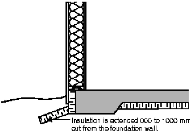
3) Where the top of a section of foundation wall is on average less than 600 mm above the adjoining ground level, the above-ground portion of that section of wall shall be insulated to the effective thermal resistance required in Table9.36.2.8.A. or9.36.2.8.B.
4) Unheated floors-on-ground that are above the frost line and have no embedded heating pipes, cables or ducts shall be insulated to the effective thermal resistance required in Table9.36.2.8.A. or 9.36.2.8.B.
a) on the exterior of the foundation wall down to the footing, or b) on the interior of the foundation wall and, as applicable,
i) beneath the slab for a distance not less than 1.2 m horizontally or vertically down from its perimeter with a thermal break along the edge of the slab that meets at least 50% of the required thermal resistance,
ii) on top of the slab for a distance not less than 1.2 m horizontally from its perimeter, or
iii) within the wooden sleepers below the floor for a distance not less than 1.2 m horizontally from its perimeter.
(See AppendixA.)
5) Except as provided in Sentence(6), floors-on-ground with embedded heating ducts, cables or pipes shall be insulated to the effective thermal resistance required in Table9.36.2.8.A. or9.36.2.8.B. under their full bottom surface including the edges.
6) Where only a portion of a floor-on-ground has embedded heating ducts, cables or pipes, that heated portion shall be insulated to the effective thermal resistance required in Table9.36.2.8.A. or 9.36.2.8.B. under its full bottom surface to 1.2 m beyond its perimeter including exterior edges if applicable.
7) In addition to the requirements stated in Sentences(5) and(6), heated floors-on-ground shall be insulated to the effective thermal resistance required in Table9.36.2.8.A. or9.36.2.8.B. vertically a) around their perimeter, or
b) on the outside of the foundation wall, extending down to the level of the bottom of the floor.
8) Floors on permafrost shall be insulated to the effective thermal resistance required in Table9.36.2.8.A. or9.36.2.8.B. under the entire slab and around all edges, and under the integral perimeter footing.
9) Slabs-on-grade with an integral perimeter footing shall
a) be insulated to the effective thermal resistance required in Table9.36.2.8.A. or9.36.2.8.B. under the entire slab and around all edges, but not under the integral perimeter footing, and
b) be constructed with skirt insulation having the same effective thermal resistance as the insulation installed under the slab.
(See AppendixA.) (See also Sentences9.25.2.3.(5) and9.36.2.5.(8).)
10) Junctions between below-grade assemblies shall be protected from the ingress of soil gas in conformance with Subsection9.25.3.
9.36.2.9. Airtightness
1) The leakage of air into and out of conditioned spaces shall be controlled by constructing
a) a continuous air barrier system in accordance with Sentences(2) to(6), Subsection9.25.3. and Article 9.36.2.10.,
b) a continuous air barrier system in accordance with Sentences(2) to(6) and Subsection9.25.3. and a building assembly having an air leakage rate not greater than 0.20 L/(s·m2) (Type A4) when tested in accordance with CAN/ULC-S742, “Air Barrier Assemblies – Specification,” at a pressure differential of 75 Pa, or
c) a continuous air barrier system in accordance with Sentences(2) to(6) and Subsection9.25.3. and a building assembly having an air leakage rate not greater than 0.20 L/(s·m2) when tested in accordance with ASTM E 2357, “Determining Air Leakage of Air Barrier Assemblies.” (See AppendixA.)
2) An air barrier system installed to meet the requirements of Sentence(1) shall be continuous a) across construction, control and expansion joints,
b) across junctions between different building materials and assemblies, and c) around penetrations through all building assemblies.
3) Windows, doors and skylights and their components shall comply with the minimum air leakage requirements stated in
a) AAMA/WDMA/CSA 101/I.S.2/A440, “NAFS – North American Fenestration Standard/Specification for Windows, Doors, and Skylights” (Harmonized Standard), and
b) CSA A440S1, “Canadian Supplement to AAMA/WDMA/CSA 101/I.S.2/A440, NAFS – North
American Fenestration Standard/Specification for Windows, Doors, and Skylights” (Canadian Supplement).
4) Vehicular access doors that separate heated garages from unconditioned spaces or the exterior shall be weatherstripped around their perimeter to prevent air leakage.
5) Fireplaces shall be equipped with doors, enclosures or devices to restrict air movement through the chimney when the fireplace is not in use. (See AppendixA.)
6) Where the airtight material used in the air barrier system is installed toward the exterior of the building envelope, its location and properties shall conform to Subsection9.25.5. (See AppendixA.) 9.36.2.10. Construction of Air Barrier Details
1) Materials intended to provide the principal resistance to air leakage shall conform to CAN/ULC-S741, “Air Barrier Materials – Specification.”
(See A-9.25.5.1.(1) in Appendix A for air leakage characteristics and water vapour permeance values for a number of common materials.)
2) Materials referred to in Sentence(1) shall be a) compatible with adjoining materials, and b) free of holes and cracks.
(See A-9.36.2.10.(5)(b) in Appendix A.)
3) Where the air barrier system consists of rigid panel-type material, all joints shall be sealed. (See A-9.36.2.10.(5)(b) in Appendix A.)
4) Where the air barrier system consists of timber logs, all joints shall be sealed to resist airflow through gaps between logs that have shifted due to in-service conditions such as shrinkage and settling. 5) Where the air barrier system consists of flexible sheet material, all joints shall be
a) lapped not less than 50 mm, b) sealed (see AppendixA), and c) structurally supported.
6) Sealant material used for the purpose of creating a continuous air barrier system shall a) be a non-hardening type, or
b) conform to i) Subsection9.27.4.,
ii) CAN/ULC-S710.1, “Thermal Insulation – Bead-Applied One Component Polyurethane Air Sealant Foam, Part 1: Material Specification,” or
iii) CAN/ULC-S711.1, “Thermal Insulation – Bead-Applied Two Component Polyurethane Air Sealant Foam, Part 1: Material Specification.”
7) Penetrations by electrical wiring, outlets, switches or recessed light fixtures through the plane of airtightness shall be constructed airtight
a) where the component is designed to provide a seal against air leakage, by sealing the component to the air barrier material (see AppendixA), or
b) where the component is not designed to provide a seal against air leakage, by covering the component with an air barrier material and sealing it to the adjacent air barrier material.
8) The joints between the foundation wall and the sill plate, between the sill plate and rim joist, between the rim joist and the subfloor material, and between the subfloor material and the bottom plate of the wall above shall be constructed airtight by
a) sealing all joints and junctions between the structural components, or
b) covering the structural components with an air barrier material and sealing it to the adjacent air barrier material.
9) The interfaces between windows, doors and skylights and wall/ceiling assemblies shall be constructed airtight by sealing all joints and junctions between the air barrier material in the wall and the window, door or skylight frame. (See AppendixA.) (See also Subsection9.7.6.)
10) Cantilevered floors and floors over unheated spaces or over the exterior shall be constructed airtight by one of the following methods or a combination thereof:
a) sealing all joints and junctions between the structural components, or
b) covering the structural components with an air barrier material and sealing it to the adjacent air barrier material.
11) Interior walls that meet exterior walls or ceilings whose plane of airtightness is on the interior of the building envelope and knee walls that separate conditioned space from unconditioned space shall be constructed airtight by
a) sealing all junctions between the structural components,
b) covering the structural components with an air barrier material and sealing it to the adjacent air barrier material, or
c) maintaining the continuity of the air barrier system above or through the interior wall or below or through the knee wall, as applicable.
12) Steel-lined chimneys that penetrate the building envelope shall be constructed airtight by blocking the void between required clearances for metal chimneys and surrounding construction with sheet metal and sealant capable of withstanding high temperatures.
13) Masonry or concrete chimneys that penetrate the building envelope shall be constructed airtight by mechanically fastening a metal flange or steel stud that extends not less than 75 mm out from the chimney and sealing the air barrier material to it with a sealant capable of withstanding high temperatures.
14) Ducts that penetrate the building envelope shall be constructed airtight by sealing the penetration through the building envelope. (See AppendixA.)
15) Plumbing vent stack pipes that penetrate the building envelope shall be constructed airtight by a) sealing the air barrier material to the vent stack pipe with a compatible sealant or sheathing tape, or b) installing a rubber gasket or prefabricated roof flashing at the penetration of the plane of airtightness
16) Where a party wall meets the plane of airtightness, that junction shall be constructed airtight by sealing any voids within the party wall at the perimeter to the adjacent air barrier material and by
a) sealing all junctions between the structural components, or
b) covering the structural components with an air barrier material and sealing it to the adjacent air barrier material.
17) Where the concrete in a flat insulating concrete form wall acts as the air barrier, the continuity of the plane of airtightness shall be maintained between the concrete and adjacent air barrier
materials.
9.36.2.11. Trade-off Options for Above-ground Building Envelope Components and Assemblies
(See AppendixA.)
1) Subject to the limitations stated in Sentences(6) to(8), the trade-off options described in Sentences(2) to(4) apply only to above-ground building envelope components and assemblies, or portions thereof, of a single building.
2) The effective thermal resistance of one or more above-ground opaque building envelope assemblies is permitted to be less than that required in Article9.36.2.6., provided
a) the total areas of all proposed and reference assemblies are equal,
b) the effective thermal resistance of one or more other proposed above-ground opaque building envelope assembly areas is increased to more than that required by Article9.36.2.6., and c) the sum of the areas of all traded above-ground opaque building envelope assemblies divided by their
respective effective thermal resistance is less than or equal to what it would be if all assemblies complied with Article9.36.2.6.
(See AppendixA and A-9.36.2.11.(2) and (3) in Appendix A.)
3) The effective thermal resistance of one or more windows, as calculated in accordance with Sentence (5), is permitted to be less than that required in Article9.36.2.7., provided
a) the total areas of all traded windows are equal,
b) the traded windows are located in the same orientation,
c) the effective thermal resistance of one or more other windows is increased to more than that required by Article9.36.2.7., and
d) the sum of the areas of all traded windows divided by their respective effective thermal resistance is less than or equal to what it would be if all windows complied with Article9.36.2.7.
(See AppendixA and A-9.36.2.11.(2) and (3) in Appendix A.)
4) The effective thermal resistance of one or more portions of floor insulation or ceiling insulation in attics under sloped roofs in buildings that are one storey in building height is permitted to be less than that required in Article9.36.2.6., provided
a) the total area of fenestration, excluding skylights, and doors does not exceed 15% of the above-ground gross wall area as calculated in accordance with Article9.36.2.3.,
b) the floor-to-ceiling height measured from the top of the subfloor to the underside of the finished ceiling of the storey does not exceed 2.34 m,
c) the distance measured from the top of the subfloor to the underside of the bottom chord of the truss or joist of the roof is not more than 2.39 m, and
d) the difference between the sum of the proposed areas of ceilings or floors divided by their respective proposed effective thermal resistance and the sum of the reference areas of ceilings or floors divided by their respective thermal resistance required in Article9.36.2.6. is not more than the difference between 17% fenestration and door area and the proposed fenestration and door areas divided by the required effective thermal resistance values for windows and doors in Article9.36.2.7.
(See AppendixA andA-9.36.2.11.(2) and (3) in Appendix A.)
5) The effective thermal resistance of windows shall be determined using the following equation: RSI = 1/U.
6) The reduction in effective thermal resistance of above-ground opaque building envelope assemblies permitted by Sentences(2) and(4) shall result in an RSI value that is not less than
a) 55% of that required in Article9.36.2.6. for above-ground walls and joist-type roofs (see AppendixA), and
b) 60% of that required in Article9.36.2.6. for other opaque assemblies.
7) The effective thermal resistances of above-ground opaque assemblies with embedded heating cables, pipes or membranes are not permitted to be traded.
8) The effective thermal resistances of doors and access hatches described in Sentences9.36.2.7.(3) to(7) are not permitted to be traded.
9.36.3. HVAC Requirements
9.36.3.1. Scope and Application1) This Subsection is concerned with the efficient use of energy by systems and equipment used for heating, ventilating and air-conditioning (HVAC).
2) Where HVAC systems, equipment or techniques other than those described in this Subsection are used, the building shall be designed and constructed in accordance with the energy efficiency requirements of the NECB.
9.36.3.2. Equipment and Ducts
1) HVAC systems shall be sized in accordance with good practice as described in Sections9.32. and9.33. (See AppendixA.)
2) Ducts shall be designed and installed in accordance with Sections9.32. and9.33. (See AppendixA.) 3) Except for exhaust ducts leading directly to the exterior, ducts and plenums carrying conditioned air
and located outside the plane of insulation shall
a) except as provided in Sentence(4), have all joints sealed against air infiltration and exfiltration with i) sealants or gaskets made from liquids, mastics or heat-applied materials,
ii) mastic with embedded fabric, or iii) foil-faced butyl tape, and
b) except as provided in Sentence(5), be insulated to the same level as required in Subsection9.36.2. for exterior above-ground walls.
4) Fabric-backed tape with rubber adhesives shall not be used as a primary sealant to meet the requirements of Clause(3)(a).
5) The underside of rectangular ducts installed under an insulated floor over an unconditioned space is permitted to be insulated to a lower level than required in Sentence(3) but not to less than 2.11 (m2·K)/W, provided both sides of such ducts are insulated to a compensating higher thermal resistance so that the resulting heat loss does not exceed that of ducts complying with Sentence (3). (See AppendixA.)
9.36.3.3. Air Intake and Outlet Dampers
1) Except as provided in Sentences(3) and(4), every duct or opening intended to discharge air to the outdoors shall be equipped with
a) a motorized damper, or
b) a gravity- or spring-operated backflow damper.
2) Except as provided in Sentences(3) and(4) and except in locations with fewer than 3500 heating degree-days as listed in Appendix C, every outdoor air intake duct or opening shall be equipped with a motorized damper that remains in the “open” position if the damper fails. 3) Where other regulations are in effect that do not permit dampers, air intakes and outlets need not
comply with Sentences(1) and(2).
4) Air intakes and outlets serving HVAC systems that are required to operate continuously need not comply with Sentences(1) and(2). (See AppendixA.)
9.36.3.4. Piping for Heating and Cooling Systems
1) Piping for heating and cooling systems shall be designed and installed in accordance with Subsection 9.33.8. (See AppendixA.)
2) Except for high-temperature refrigerant piping, all piping forming part of a heating or air-conditioning system shall be located
a) inside the plane of insulation, or
b) within or outside the plane of insulation, provided the piping is insulated to a thermal resistance not less than that required in Subsection9.36.2. for exterior above-ground walls.
(See AppendixA.)
9.36.3.5. Equipment for Heating and Air-conditioning Systems 1) Equipment for heating and air-conditioning systems shall be located a) inside the plane of insulation, or
b) outdoors or in an unconditioned space, provided the equipment is designated by the manufacturer for such installation.
(See AppendixA.)
9.36.3.6. Temperature Controls
1) Except for manually fuelled solid-fuel-fired appliances, the supply of heating and cooling energy to each dwelling unit, suite or common space shall be controlled by thermostatic controls that activate the appropriate supply when the temperature in a conditioned space fluctuates ±0.5°C from the set-point temperature for that space.
2) Where heating and cooling systems are controlled by separate thermostatic controls, means shall be provided to prevent these controls from simultaneously calling for heating and cooling. 3) Space temperature control devices used to control unitary electric resistance space heaters shall
conform to CAN/CSA-C828, “Thermostats Used with Individual Room Electric Space Heating Devices.”
4) Controls required by Sentence(1) shall be designed such that lowering the set-point temperature on the thermostat for the heating system will not cause cooling energy to be expended to reach the lowered setting, and raising the set-point temperature on the thermostat for the cooling system will not cause heating energy to be expended to reach the raised setting.
5) Automatic devices or manually operated dampers, valves or switches shall be provided, as appropriate for the heating system used, to allow the heating of each zone to be adjusted. 6) Heat pumps equipped with supplementary heaters shall incorporate controls to prevent
supplementary heater operation when the heating load can be met by the heat pump alone, except during defrost cycles.
7) Heat pumps with a programmable thermostat shall be equipped with setback controls that will temporarily suppress electrical back-up or adaptive anticipation of the recovery point, in order to prevent the activation of supplementary heat during the heat pump’s recovery. (See
AppendixA.) 9.36.3.7. Humidification
1) Where an HVAC system is equipped with a means for adding moisture to maintain specific humidity levels, an automatic humidity control device shall be provided.
9.36.3.8. Heat Recovery from Dehumidification in Spaces with an Indoor Pool or Hot Tub
(See AppendixA.)
1) Except as provided in Sentences(2) and(3), spaces containing an indoor pool or hot tub shall be equipped with air exhaust systems conforming to Sentence(4) at design conditions. (See also Article9.25.4.2.)
2) Spaces containing an indoor pool need not comply with Sentence(1), provided a stationary
mechanical or desiccant dehumidification system is installed that provides at least 80% of the dehumidification that would result from compliance with Sentence(1).
3) Spaces containing an indoor pool or hot tub having a total water surface area of less than 10 m2 need not comply with Sentence(1), provided they are equipped with a cover having a nominal thermal resistance not less than 2.1 (m2·K)/W.
4) Heat-recovery systems used to meet the requirements of Sentence(1) shall
a) be capable of recovering at least 40% of the sensible heat from exhausted air when tested in
accordance with ANSI/AHRI 1060, “Performance Rating of Air-to-Air Exchangers for Energy Recovery Ventilation,”(see AppendixA), or
b) have a sensible-heat-recovery efficiency complying with Sentence9.36.3.9.(3) when tested in accordance with CAN/CSA-C439, “Rating the Performance of Heat/Energy-Recovery Ventilators.”
5) The sensible heat, in kW, referred to in Clause(4)(a), which is the sensible heat content of the total quantity of exhausted air, shall be calculated as follows:
where
Te = temperature of exhausted air before heat recovery, in °C,
To = outdoor 2.5% January design temperature as listed in Appendix C, in °C, and
Q = rated capacity of exhaust system at normal temperature of exhausted air, in L/s. 9.36.3.9. Heat Recovery from Ventilation Systems
1) This Article applies where a self-contained mechanical ventilation system is installed whose principal exhaust component is equipped with heat-recovery capability. (See AppendixA.)
2) Where an integrated mechanical system (IMS) with a heat-recovery ventilator provides the principal exhaust ventilation, the IMS shall
a) be tested in accordance with CSA P.10, “Performance of Integrated Mechanical Systems for Residential Heating and Ventilation,” and
b) have a minimum overall thermal performance factor conforming to Table9.36.3.10.
3) When tested in conformance with the low-temperature thermal and ventilation test methods
described in CAN/CSA-C439, “Rating the Performance of Heat/Energy-Recovery Ventilators,” heat-recovery ventilators described in Sentence(1) shall have a sensible heat-recovery
efficiency of
a) at least 60% at an outside air test temperature of 0°C for locations with a 2.5% January design temperature greater than or equal to –10°C, and
b) at least 60% at an outside air test temperature of 0°C and at least 55% at an outside air test
temperature of –25°C for locations with a 2.5% January design temperature less than –10°C. (See AppendixA.)
4) The requirements of Sentence (3) shall be met using a principal ventilation rate not less than that required in Section9.32. (See A-9.36.3.9.(3) in Appendix A.)
9.36.3.10. Equipment Efficiency
1) HVAC equipment and components shall comply with the performance requirements stated in Table 9.36.3.10. (See AppendixA.)
Table 9.36.3.10.
HVAC Equipment Performance Requirements
Forming Part of Sentences 9.36.3.9.(2) and 9.36.3.10.(1)
Component or Equipment Heating or Cooling
Capacity, kW Standard Minimum Performance
(1)
Air-Cooled Unitary Air Conditioners and Heat Pumps – Electrically Operated
Split system ≤ 19 CAN/CSA-C656
SEER = 14.5 EER = 11.5 HSPF = 7.1 (region 5 in standard) Single-package system ≤ 19 CAN/CSA-C656 (including General Instruction No. 2) SEER = 14 EER = 11 HSPF = 7.0 (region 5 in standard)
All systems > 19 CAN/CSA-C746 See Level 2 in standard
Water-Cooled Unitary Air Conditioners and Heat Pumps – Electrically Operated
Ground-source and water-source heat pumps
open loop < 40 CAN/CSA-C13256-1 COPc≥ 4.75, COPh≥ 3.6
closed loop COPc≥ 3.93, COPh≥ 3.1
Water-to-water heat pumps
open loop < 40 CAN/CSA-C13256-2 COPc≥ 5.60, COPh≥ 3.4
closed loop COPc≥ 4.21, COPh≥ 2.8
Internal water-loop heat pumps
< 5
CAN/CSA-C13256-1
COPc≥ 3.28, COPh≥ 4.2
≥ 5 and ≤ 40 COPc≥ 3.52, COPh≥ 4.2
Water-cooled air
conditioners – all types
< 19 ANSI/AHRI 210/240 or CTI
201 COP = 3.54, ICOP = 3.60
Direct-expansion ground-source heat pumps ≤ 21 CSA C748 EER = 13.0 COPh = 3.1
Room Air Conditioners and Room Air Conditioner Heat Pumps
Room air conditioners with reverse cycle
with louvered sides < 10.55 ANSI/AHAM RAC-1 EER = 8.5
without louvered sides EER = 8.0
Room air conditioners without reverse cycle and with louvered sides < 1.8 CAN/CSA-C368.1 EER = 10.7 ≥ 1.8 and < 2.3 EER = 10.7 ≥ 2.3 and < 4.1 EER = 10.8 ≥ 4.1 and < 5.9 EER = 10.7 ≥ 5.9 EER = 9.4
Room air conditioner heat pumps with louvered sides
< 5.9 EER = 9.9
≥ 5.9 EER = 9.5
Room air conditioners without louvered sides and without reverse cycle < 1.8 EER = 9.9 ≥ 1.8 and < 2.3 EER = 9.9 ≥ 2.3 and < 4.1 EER = 9.4 ≥ 4.1 and < 5.9 EER = 9.4 ≥ 5.9 EER = 9.4
Room air conditioner heat pumps without louvered sides
< 4.1 EER = 9.2
≥ 4.1 EER = 8.8
Room air conditioner,
casement only All capacities
EER = 9.5
Room air conditioner,
casement slider All capacities
EER = 9.5
Boilers
Electric boilers ≤ 88 —
Must be equipped with automatic water temperature control(2)
> 88 and ≤ 117.23 AHRI BTS Et≥ 83%
Oil-fired boilers ≤ 88 CSA B212 or
ANSI/ASHRAE 103
AFUE ≥ 85%
Warm-Air Furnaces, Combination Warm-Air Furnace/Air-conditioning Units, Duct Furnaces and Unit Heaters
Gas-fired warm-air ≤ 65.9 furnaces(3)
CAN/CSA-P.2 AFUE ≥ 92% > 65.9 and ≤ 117.23 CAN/CSA-P.8 Et≥ 78.5%
Gas-fired duct furnaces(3) ≤ 117.23 ANSI Z83.8/CSA 2.6 E
t≥ 81%
Gas-fired unit heaters(3) ≤ 117.23 CAN/CSA-P.11 E
t≥ 82%
Oil-fired warm-air furnaces ≤ 66 CSA B212 AFUE ≥ 85% Oil-fired duct furnaces and
unit heaters — UL 731 Ec≥ 80%
Combined space- and water-heating systems (combos) ≤ 87.9 if boiler-based CAN/CSA-P.9(4) TPF = 0.65 ≤ 73.2 if based on service water heater Integrated mechanical
systems — CSA P.10 OTPF = 0.78
Other
Gas-fired fireplaces and — stoves(3) — (5) Solid-fuel-burning space-heating equipment — EPA 40 CFR, Part 60, Subpart AAA or CSA B415.1(6) See standard(7)
Dehumidifiers ≤ 87.5 L/day CAN/CSA-C749 See standard(7)
Notes to Table 9.36.3.10.:
(1)
The symbols and abbreviations that appear in this column have the following meanings: AFUE = annual fuel utilization efficiency
COP = coefficient of performance, in W/W (COPc = in cooling mode and COPh = in heating mode) Ec = combustion efficiency, in %
EER = energy efficiency ratio, in (Btu/h)/W (no metric equivalent) Et = thermal efficiency
FE = fireplace efficiency
HSPF = heating season performance factor, in watt-hours ICOP = integrated coefficient of performance, in W/W OTPF = overall thermal performance factor
SEER = seasonal energy efficiency ratio, in (Btu/h)/W (no metric equivalent) TPF = thermal performance factor
(2) No standard addresses the performance efficiency of electric boilers; however, their efficiency typically approaches 100%. (3) Includes propane.
(4) See the exception stated in Sentence (3) (5) See
. Sentence (2)
(6)
.
CSA B415.1 does not apply to stoves with an oven whose volume is greater than 0.028 m3
and automatically fuelled appliances.
(7) Minimum performance values are omitted from the Table in cases where the referenced standard itself contains such
requirements.
2) Natural gas and propane fireplaces shall be a) direct-vent (sealed), and
b) pilot-on-demand, interrupted or intermittent ignition systems without a standing pilot light.
3) The heat source component of combined space- and service water heating systems that are not within the scope of CAN/CSA-P.9, “Performance of Combined Space and Water Heating Systems (Combos),” shall meet the performance requirements stated in Table9.36.3.10. for the applicable equipment type. (See AppendixA.)
9.36.3.11. Solar Thermal Systems
1) Space-heating systems that use solar thermal technology shall conform to the manufacturer’s design requirements and installation procedures.
2) Service water heating systems that use solar thermal technology shall be installed in accordance with Book II (Plumbing Systems) of this Code.
3) Hot water storage tanks associated with the systems referred to in Sentence(2) shall be installed in a conditioned space.
9.36.4. Service Water Heating Systems
9.36.4.1. Scope and Application1) This Subsection is concerned with the efficient use of energy by systems used to heat service water for household use as well as for indoor pools and hot tubs.
2) Where service water heating equipment or techniques other than those described in this Subsection are used, the building shall be designed and constructed in accordance with the energy efficiency requirements of the NECB.
9.36.4.2. Equipment Efficiency
1) Service water heaters, boilers, pool heaters and storage tanks shall comply with the performance requirements stated in Table9.36.4.2. (See AppendixA.)
2) Hot service water storage tanks not listed in Table9.36.4.2. shall be covered with insulation having a minimum thermal resistance of 1.8 (m2·K)/W.
Table 9.36.4.2.
Service Water Heating Equipment Performance Standards
Component Input(1)
Standard Performance
Requirement(2)
Storage-Type Service Water Heaters
Electric ≤ 12 kW (50 L to 270 L capacity) CAN/CSA-C191 SL ≤ 25 + 0.20V (top inlet) SL ≤ 40 + 0.20V (bottom inlet) ≤ 12 kW (> 270 L and ≤ 454 L capacity) SL ≤ (0.472V) – 38.5 (top inlet) SL ≤ (0.472V) – 33.5 (bottom inlet) >12 kW (> 75 L capacity) ANSI Z21.10.3/CSA 4.3 and DOE 10 CFR, Part 431, Subpart G S = 0.30 + 27/Vm
Heat pump water heaters ≤ 24 A and ≤ 250 V CAN/CSA-C745 EF ≥ 2.0
Gas-fired(3)
< 22 kW CAN/CSA-P.3 EF ≥ 0.67 – 0.0005V
≥ 22 kW ANSI Z21.10.3/CSA 4.3
Et≥ 80% and standby loss
≤ rated input(4) /(800 + 16.57·√V) Oil-fired ≤ 30.5 kW CAN/CSA-B211 EF ≥ 0.59 – 0.0005V > 30.5 kW ANSI Z21.10.3/CSA 4.3 and DOE 10 CFR, Part 431, Subpart G
Et≥ 78% and standby loss
≤ rated
input(4)/(800 +
16.57·√V) Tankless Service Water Heaters
Gas-fired(3) ≤ 73.2 kW CAN/CSA-P.7 EF ≥ 0.8 > 73.2 kW ANSI Z21.10.3/CSA 4.3 and DOE 10 CFR, Part 431, Subpart G Et≥ 80% Oil-fired ≤ 61.5 kW(5) DOE 10 CFR, Part 430, Subpart B, Appendix E EF ≥ 0.59 − 0.0019Vm Other ANSI Z21.10.3/CSA 4.3 and DOE 10 CFR, Part 431, Subpart G Et≥ 80% Electric — — (6)
water-heating systems (combos) ≤ 73.2 kW if based on service water heater Integrated mechanical
systems — CSA P.10 OTPF = 0.78
Pool Heaters
Gas-fired(3) < 117.2 kW ANSI Z21.56/CSA 4.7 or
CSA P.6 Et≥ 82%
Oil-fired — CSA B140.12 Et≥ 75%
Notes to Table 9.36.4.2.:
(1)
1 kW = 3.412 Btu/h
(2) The symbols and abbreviations used in this column have the following meanings:
EF = energy factor, in %/h
Et = thermal efficiency with 38.9°C water temperature difference OTPF = overall thermal performance factor
S = standby loss, in %/h (percentage heat content of stored water per hour) SL = standby loss, in W
TPF = thermal performance factor
V = storage volume, in L, as specified by the manufacturer Vm = measured storage volume, in US gallons
(3)
Includes propane.
(4) Rated input is measured in watts.
(5) Consistent with the US Congress National Appliance Energy Conservation Act of 1987.
(6) No standard addresses the performance efficiency of electric tankless service water heaters; however, their efficiency typically
approaches 100%.
3) Except for components that are required to be installed outdoors, service water heating equipment shall be installed in a conditioned space. (See AppendixA.)
9.36.4.3. Solar Domestic Hot Water Systems
1) Service water heating systems that use solar thermal technology shall conform to the manufacturer’s design requirements and installation procedures.
2) Service water heating systems that use solar thermal technology shall be installed in accordance with Book II (Plumbing Systems) of this Code.
3) Hot water storage tanks associated with the systems referred to in Sentence(2) shall be installed in a conditioned space.
9.36.4.4. Piping
1) The first 2 m of outlet piping downstream and of inlet piping upstream leading from a storage tank or heating vessel shall be covered with piping insulation that is at least 12 mm thick.
2) All piping forming part of a continuously operating recirculating service water heating system shall be covered with piping insulation that is at least 12 mm thick.
3) Where piping forming part of the service water heating system is located outside the building
envelope or in an unconditioned space, it shall be insulated to a thermal resistance not less than the effective thermal resistance required for the exterior above-ground walls.
9.36.4.5. Controls
1) Service water heating systems with storage tanks shall be equipped with automatic temperature controls capable of adjustment between the minimum and maximum temperature settings permitted for the intended use.
9.36.4.6. Indoor Swimming Pool Equipment Controls 1) Heaters for indoor swimming pools shall be equipped with a) a thermostat, and
b) a readily accessible and clearly labeled device that allows the heater to be shut off without adjusting the thermostat setting.
2) Pumps and heaters for indoor swimming pools shall be equipped with time switches or other types of controls that can be set to automatically turn off the pumps and heaters when their operation is not required. (See AppendixA.)
9.36.5. Energy Performance Compliance
9.36.5.1. Scope and Application1) This Subsection is concerned with modeling the energy performance of components, systems and assemblies, including heat gains from internal loads described in Sentence9.36.5.4.(4), that are addressed in the scope of the prescriptive requirements in Subsections9.36.2. to9.36.4. and that are installed in buildings described in Sentence9.36.1.3.(3).
2) Internal loads other than those described in Sentence9.36.5.4.(4) shall be excluded from the performance compliance calculations as they relate to
a) the lighting of unconditioned spaces, b) exterior lighting, and
c) the ventilation of unconditioned spaces. 9.36.5.2. Definitions
(See AppendixA.)
1) For the purpose of this Subsection, the term “reference house” shall mean a hypothetical replica of the proposed house design using the same energy sources for the same functions and having the same environmental requirements, occupancy, climatic data and operating schedules, but made to comply with all applicable prescriptive requirements of Subsections9.36.2. to9.36.4.
2) For the purpose of this Subsection, the term “annual energy consumption” shall mean the annual sum of service water heating and space-conditioning energy consumption of the proposed house design, as calculated in accordance with this Subsection.
3) For the purpose of this Subsection, the term “house energy target” shall mean the annual energy consumption of the reference house, as calculated in accordance with this Subsection. 4) For the purpose of this Subsection, the term “principal ventilation rate” shall mean the normal
operating exhaust capacity of the principal ventilation fan as required by Article9.32.3.3. 9.36.5.3. Compliance
1) The performance compliance calculations shall determine a) the annual energy consumption of the proposed house, and b) the house energy target of a reference house.
2) The annual energy consumption of the proposed house shall not exceed the house energy target of the reference house. (See AppendixA.)
3) In establishing the house energy target, building components, systems and assemblies shall be
accounted for in accordance with the prescriptive requirements of Subsections9.36.2. to9.36.4. for the climate zone under consideration.
4) In establishing the annual energy consumption, building components, systems and assemblies that are addressed in the scope of the prescriptive requirements of Subsections9.36.2. to9.36.4. shall be accounted for for the climate zone under consideration.
5) Where the construction techniques or building components, systems or assemblies used are more energy-efficient than those prescribed by the prescriptive requirements, the performance compliance calculations are permitted to take this increased performance level into account in the determination of the annual energy consumption, provided it can be quantified and is not dependent on occupant interaction.
6) Both the proposed and reference houses shall be modeled using the same climatic data, soil conditions, operating schedules in Article9.36.5.4. and temperature set-points. 9.36.5.4. Calculation Methods
1) Except as provided in Sentence(2), the energy model calculations shall account for the annual energy consumption of systems and equipment required for
a) space heating, b) ventilation,
c) service water heating, and d) where installed, space cooling. (See AppendixA.)
2) Redundant or back-up equipment for the systems and equipment listed in Sentence(1) is permitted to be excluded from the energy model, provided it is equipped with controls and is not required to meet the space-conditioning load of the house. (See AppendixA.)
3) The schedules used in the energy model shall
a) be based on a time interval not greater than one hour, where the energy model evaluates the performance of the house over hourly intervals, or
b) be applied in an hourly-bin model then averaged, where the energy model does not evaluate the performance of the house over hourly intervals.
4) The energy model calculations shall account for the loads due to heat gains from occupants, lighting and miscellaneous equipment using the default schedule provided in Table9.36.5.4. for every day of the year and such loads shall be
a) multiplied by the following adjustment factors, as applicable: i) 1 for a house with or without a secondary suite,
ii) 0.625 for each suite in a residential building containing 2 suites, iii) 0.606 for each suite in a residential building containing 3 suites, or
iv) 0.598 for each suite in a residential building containing more than 3 suites, and
b) increased for each hour by 3.58 W per square metre of floor area in common spaces, if applicable. Table 9.36.5.4.
Default Schedule for Internal Heat Gain Loads(1)
Forming Part of
Average Load, in W, Before Noon
Sentence 9.36.5.4.(4)
12 1 a.m. 2 a.m. 3 a.m. 4 a.m. 5 a.m. 6 a.m. 7 a.m. 8 a.m. 9 a.m. 10 11 a.m.
786 552 549 523 521 547 634 726 847 880 906 986
Average Load, in W, After Noon
12 1 p.m. 2 p.m. 3 p.m. 4 p.m. 5 p.m. 6 p.m. 7 p.m. 8 p.m. 9 p.m. 10 11 p.m.
992 934 898 911 924 1 089 1 410 1 588 1 568 1 483 1 194 952
Notes to Table 9.36.5.4.:
(1) The schedule indicates at what time of day the heat gains from internal loads and hot water draws are present; it does not
account for heat gains from exterior lighting and from lighting of unconditioned spaces.
5) The energy model calculations shall account for the following space-heating temperature set-points: a) 21°C in all living spaces above the basement,
b) 19°C in basements and common spaces, and
6) The energy model calculations shall account for a space-cooling temperature set-point of 25°C in all conditioned spaces served by the cooling system.
7) The energy model calculations shall account for a thermostatic control that responds to fluctuations of ±0.5°C from the temperature set-point. (See AppendixA.)
8) If a computer program is used to carry out the compliance calculations, the calculation methods employed in the energy model shall
a) be used for both the reference and proposed houses, and
b) be tested in accordance with ANSI/ASHRAE 140, “Evaluation of Building Energy Analysis Computer Programs,” with variations in the computer program from the range recommended therein reported in accordance with Division C.
9) The proposed and reference houses shall both be modeled using the same approach and assumptions, except where building components or energy efficiency features are permitted by this
Subsection to be different.
10) The energy model calculations shall account for the effect of airtightness in accordance with Sentence 9.36.5.10.(10) or(11), as applicable.
11) The energy model calculations shall account for heat transfer through elements separating conditioned space from unconditioned space, the exterior or the ground.
9.36.5.5. Climatic Data
1) To calculate the effect of heating and cooling consumption, the energy model calculations shall be performed using climatic data measured at time intervals no greater than one hour for one year (8 760 hours) based on the average of at least 10 years of measured data collected at the weather station nearest to the region in which the proposed house is located. (See AppendixA.)
2) For urban regions with several climatic data sets and for locations for which climatic data are not available, the energy model calculations shall be performed using climatic data that best represent the climate at the building site.
3) The energy model calculations shall account for ground reflectance by
a) increasing ground reflectance due to snow cover in a ratio of 30% without snow cover and 70% with snow cover, or
b) taking into account changes in ground reflectance throughout the heating season. 9.36.5.6. Building Envelope Calculations
1) For each hour of the year, the energy model calculations shall account for heat transfer through wall assemblies, roof-ceiling assemblies, including attics where applicable, and exposed floor assemblies due to the thermal characteristics of the particular assembly and thermal bridging. 2) The following building envelope assemblies and components shall be addressed in the energy model
calculations:
a) above-ground walls and roof-ceiling assemblies, b) floors and walls in contact with the ground, and
c) doors, windows and skylights. (See Subsection9.36.2.)
3) For each wall assembly, fenestration component, roof-ceiling assembly and exposed floor assembly, the energy model calculations shall account for
a) the area of the interior side of the insulated surface, b) emissivity, and
c) the effective thermal resistance or overall thermal transmittance, as applicable.
4) The energy model calculations shall account for the effect that each assembly in contact with the ground has on below-grade heat transfer due to
a) the geometry of the foundation,
b) soil conditions (see A-1.1.3.1.(1) in Appendix A), and c) the configuration of the insulation.
5) The energy model calculations shall account for heat transfer through fenestration separating conditioned spaces from the outdoors, including skylights, while accounting for both temperature difference and transmission of solar radiation based on
a) orientation as a function of azimuth and tilt of the surface, b) area of frame opening and glazed area,
c) overall thermal transmittance, and d) solar heat gain coefficient.
6) Where the energy model calculations account for the effect of thermal mass, the contents of the house shall be excluded. (See AppendixA.)
7) The energy model calculations shall account for the presence of thermally active walls, floors and ceilings with embedded conditioning systems that form part of the building envelope.
8) Where skylights are installed in the roof, the gross roof area shall be determined in accordance with Sentence9.36.2.3.(3).
9) Skylights shall be considered to have no shading.
10) The energy model calculations shall account for the effects of exterior permanent and fixed shading only on solar heat gain from fenestration.
11) The ratio of fenestration area to opaque area of doors shall be the same for the proposed and reference houses. (See AppendixA.)
9.36.5.7. HVAC System Calculations
1) The energy model calculations shall account for the energy consumption of each heating, ventilating and, where installed, cooling system for each hour of the year. (See AppendixA.)
2) Each heating system and, where installed, cooling system shall be accounted for separately in the energy model calculations.