Research Note
Simple Assessment Method to
Estimate the Remaining Moment
Capacity of Corroded I-Beam Sections
Y. Shari
1;and R. Rahgozar
1Abstract. Corrosion of steel structures is a serious problem throughout the world. The most signicant consequence of corrosion is reduction of the section size. This, in turn, leads to a reduction in the carrying capacity and structural safety. The analysis of existing structures may dier from the analysis of structures under design, especially if there is damage by corrosion. Common examples of corrosion that have been found in the petro-chemical industry include the loss of sections in anges and holes in the web. As there is no clear provision of recommendations for such cases in the present codes, there is a need for simple assessment methods to deal with them eectively. The overall aim of this paper is to develop a simple method which can be used to make reliable estimates of the remaining moment capacity, using thickness loss information provided by visual inspection or measurements. The results of this study can be used for calculating the remaining service life, such as the moment capacity of deteriorated I-beams. Keywords: Uniform corrosion; Thickness loss; Steel structures; Moment capacity.
INTRODUCTION
Corrosion of steel is an electro-chemical process in which iron, Fe, reacts with oxygen to form iron oxides. Steel has been used extensively throughout the world for the construction of buildings, bridges, factories, oshore structures and all other types of structure. Corrosion is one of the most important causes of deterioration of steel in all types of structure [1].
The primary cause of corrosion is the accumula-tion of water and salt (marine environment or deicing media) on steel. The source of water and salt is either from deck leakage or from the accumulation of road spray and condensation. The source of the moisture often determines the pattern of corrosion on a beam. The rate of corrosion will depend upon the contaminants in the moisture and the ambient temperature [2].
The deterioration usually consists of thinning sections in the web or irregularly shaped holes in the web just above the ange, which may decrease the load 1. Department of Civil Engineering, University of Kerman,
Kerman, P.O. Box 76169-133, Iran.
*. Corresponding author. E-mail: yasser [email protected] Received 4 July 2009; received in revised form 5 January 2010; accepted 20 February 2010
carrying capacity in shear, bearing and bending [3]. In both the United States and the United Kingdom, the cost of corrosion has been estimated to be around 3% of the gross national product [4]. It has been pointed out by Koch et al. [5] that the United States Congress estimated the total direct cost of metal corrosion in 26 industrial sectors to be $276 billion per year.
There are a large number of steel structures where structural members and components are corroded; the corrosion has been concealed by paint and may not be visually identied. Regular inspection of steel structures is usually based on visual examination and classication into condition categories that identify the need for appropriate action. The most severe visual category refers to the presence of serious structural defects and the consequent need for full structural assessment and repair [6]. Gallon [7] found that current inspection and assessment methods, while being safe, were signicantly conservative in some instances. This may lead to plant closures with a consequential nan-cial penalty when the corrosion damaged structures are unable to carry the required loads.
There are a large number of corroded structures in dierent parts of Iran, especially in the south and north, industrial zones, reneries and petro-chemical factories. Therefore, it is very important to recognize
and fully understand the mechanism of steel corrosion, forms of corrosion and rate of corrosion penetration. These factors indicate that there is an urgent need for a more realistic assessment method for quantifying visual inspection so that the capacity of corrosion damaged steel structures may be assessed more reliably.
In this paper, the remaining moment strength of corroded I-beams is considered with uniform corrosion. The results of this study can be used for a better pre-diction of the service life (remaining moment capacity) of deteriorated I-beams.
MECHANISM OF STEEL CORROSION In order to produce steel, iron ores must be processed. During the process of metal extraction, it consumes a large amount of energy to separate the metal from the ore. This energy is essentially stored in the metal. Because of the fact that all congurations in nature tend to spontaneously change to lower states of energy, rened metal will deteriorate or corrode. In steel structures exposed to water, oxygen and salt, the rate of corrosion will be considerably increased by the presence of salt from a marine environment or the use of deicing materials. In the natural environment, it has a tendency to oxidize to a form similar to its natural state under the inuence of air and water. This deterioration process is known as corrosion. More precisely, it is an electro-chemical reaction in which water with various pollutants in the solution acts as the electrolyte. Corrosion of steel is an electro-chemical process in which iron, Fe, reacts with oxygen to form iron oxides. The familiar iron compounds are: Fe(OH)2, ferrous hydroxide; Fe(OH)3, ferric hydroxide;
Fe2O3, iron oxide; and Fe3O4, magnetite. When steel
is attacked under humid conditions in a clean rural atmosphere, the rst oxidation product is ferrous ion in the lowest oxidation state, namely, Fe+2. Because
of the presence of air dissolved in moisture, the ferrous ion can react with it and precipitate ferrous hydroxide, Fe(OH)2, which can be quickly oxidized further to the
ferric state, Fe+3, to give the gelatinous precipitate of
ferric hydroxide [8].
FORMS OF CORROSION
There are dierent forms of corrosion that can aect a steel structure. The most prevalent form is a general loss of surface material. This condition will lead to the gradual thinning of members. General corrosion ac-counts for the largest percentage of corrosion damage. Pitting corrosion also involves loss of material at the surface. However, it is restricted to a very small area. Pits can be dangerous because they extend into the metal showing little evidence of their existence. Pit oc-currence is serious in high stress regions because it can
cause local stress concentrations. Galvanic corrosion occurs when two dissimilar metals are electrochemically coupled. Such situations may occur at bolted or welded connections. Galvanic corrosion can be local, leading to pit formation. Crevice corrosion occurs in small conned areas, such as beneath peeling paint or between faying surfaces. It is usually caused by a low concentration of dissolved oxygen in the moisture held within a crevice. Deep pits can also provide locations for crevice corrosion to occur. Stress corrosion occurs when metal is subjected to tensile stress in a corrosive environment [8].
For mild carbon steel in ordinary bridge envi-ronments, stress corrosion is usually not a problem. In general, the lower fracture resistance of a metal, the higher its susceptibility to stress corrosion [9]. The combined action of both corrosion and fatigue, known as corrosion fatigue, may reduce the life of structures. Corrosion fatigue is a complex phenomenon that occurs in metal due to cyclic stresses in a corrosive environment. It has been pointed out by Kitagawa et al. [10] that increases in the cyclic stress level or the number of load cycles bring about corrosion pits on the surface. Apart from corrosion, inadmissible loads, such as overloaded vehicles on bridge decks, may reduce the fatigue life of bridges [11].
THE EFFECTS OF CORROSION ON STEEL STRUCTURES
The eects of corrosion vary with the type of structure and the location and extent of deterioration. Steel structures can be aected by corrosion in many ways. The main eects can be loss of material from the surface, which leads to thinner sections. Section loss due to uniform corrosion may take place over a large area of a structural member. The loss of material due to uniform corrosion results in the reduction of section properties of a member, such as the cross sectional area, moment of inertia, section modulus and radius of gyration, which cause a reduction in the carrying capacity of the structure. The stiness of members may also be reduced due to loss of material, which may cause excessive deection. At severe levels of corrosion, the ultimate capacity of a steel member may fall below the service loads. Also, it should be pointed out that the mode of failure due to loss of material can be changed because the class of the section can be altered. For example, a plastic section may become semi-compact due to the loss of material, and local buckling may prevent the development of full plastic moment [12].
CORROSION DECAY MODELS
Special attention has to be given to obvious corrosion areas, such as leaky expansion joints and trac spray
areas as well as to susceptible exposures and other areas, such as bolt splices and other lapped joints, debris accumulation and galvanic contact. It has been pointed out by Kayser and Nowak [13] that severe corrosion may take place at the bottom one quarter of the web. Therefore, the top surface of the bottom ange and the bottom part of the web are the regions where severe corrosion may take place as shown in Figure 1. Corrosion also takes place in the top ange and the top part of the web, but the loss is much less compared to that of the web's bottom part.
The development of a corrosion decay model mainly requires information on the location, where corrosion normally occurs, and the types of corrosion damage in steel members. The most common form of corrosion damage in steel is general surface corrosion. In this paper, the analysis of corrosion eects is carried out using the corrosion decay model described by Rahgozar [12]. Uniform corrosion is the formation of oxide distributed uniformly over an exposed surface. This is the most common form of corrosion, which will lead to the gradual thinning of members, accounting for the greatest destruction of metals [8]. This information was used for the development of the model shown in Figure 2a.
Figure 1. Typical location of corrosion in steel beam.
Figure 2a. Uniform thickness loss model [12].
The thickness loss in the bottom ange of sample beams is approximately twice that of the loss in the top ange. The thickness loss of the lower part in the web (0:25hw) is nearly ve times that of the loss in the
upper part of the web (0:75hw). These ratios were used
for the development of the models shown and described in Figure 2b.
Using this information, the corrosion decay mod-els were considered by reducing the thickness of the sections. The models which are shown in Figures 2a and 2b are:
a) Uniform thickness loss, b) Varying thickness loss.
Uniform Thickness Loss Model Sections
The corrosion decay model developed by Rahgozar [12] for the uniform thickness loss model sections is as follows:
Average thickness of anges:
TC= TN(1 ): (1a)
Thickness of web:
tC = tN(1 ); (1b)
where:
F = %LFT=100;
W = %LWT=100;
= F = W:
Varying Thickness Loss Model Sections
The corrosion decay model for varying thickness loss of beam sections is as follows:
Thickness of top ange:
TN(1 0:7): (2a)
Thickness of bottom ange:
TN(1 1:3): (2b)
Average thickness of anges:
TC = TN(1 ): (2c)
Thickness of the upper part of the web:
(0:75hw) = tN(1 0:25): (2d)
Thickness of the lower part of the web:
(0:25hw) = tN(1 1:25): (2e)
Average thickness of web:
tC= tN(1 0:5); (2f)
where:
= F = 2W:
In this case, the average thickness is used to calculate the percentage loss of both anges and web thickness.
SIMPLE ASSESSMENT METHOD FOR MOMENT CAPACITY
The loss of thickness in the anges and web due to corrosion results in a reduction in the moment capacity. Beside this, the loss of thickness may change the class of an element (plastic, compact, semi-compact) from one to another. The theory given in this study will be used for evaluation of the remaining moment capacity of corrosion damaged beams.
The moment capacity, Mc, is as follows:
For Plastic and Compact Sections For corrosion damaged sections:
McC = PyZC; but < 1:2PySC: (3a)
For as-new sections:
McN = PyZN; but < 1:2PySN: (3b)
For Semi-Compact Sections For corrosion damaged sections:
McC = PySC: (4a)
For as-new sections:
McN = PySN; (4b)
where Py is the design strength, Z is the plastic
modulus of the section about the relevant axis, and S is the elastic modulus of the section about the relevant axis.
The percentage Remaining Moment Capacity (%RMC) of a corrosion damaged section is the ratio of the capacity of the corrosion damaged section (McC)
to the capacity of the as-new section (McN), which can
be expressed as:
%RMC = 100(McC=McN): (5)
For corrosion damaged beams of the same section size, the overall dimensions, B, D and hw, can be considered
as constant throughout their service life, although there will be a small reduction due to corrosion. Therefore, the plastic modulus of an I-section with equal anges about its major axis may be given by:
For corrosion damaged sections: ZXC = BTC(D TC) + tCh
2 W
4 : (6a)
For as-new sections:
ZXN = BTN(D TN) + tNh 2 W
4 : (6b)
DEVELOPMENT OF DECAY MODELS FOR STEEL I-BEAM SECTIONS
Uniform Thickness Loss Model Sections
Substituting for TC and tC(Equations 1a and 1b) into
Equation 6a, gives the plastic modulus of corrosion damaged I-sections as:
ZXC =
BTN(D TN) + tNh 2 w
4
BTN(D 2TN) + tNh 2 w
4
BT2
N2: (7)
The rst bracketed term of Equation 7 is the plastic modulus of as-new sections given by Equation 6b. Now, using the following approximation;
BTN(D 2TN) + tNh 2 w
4 ZXN; (8)
by neglecting the 2 term, the plastic modulus of
ZXC ZXN ZXN ZXN(1 ): (9)
Varying Thickness Loss Model Sections
Substituting for TC and tC (Equations 2c and 2f) into
Equation 6a, gives the plastic modulus of corrosion damaged I-sections as:
ZXC =
BTN(D TN) + tNh 2 W
4
BTN(D 2TN) + tNh 2 W
4
+ tNh 2 W
8 BTN22: (10)
Equation 6b is substituted into Equation 10, and the 2term is neglected. The following relation is obtained
for the plastic modulus of corrosion damaged sections:
ZXC ZXN
ZXN tNh 2 W
8
; (11)
where the term, tNh
2 W
8 , of Equation 11 is the plastic
modulus of half of the shear area.
CLASS OF SECTION UNCHANGED BY CORROSION
Although corrosion reduces the thickness of the com-pression ange of a section, some sections that are plas-tic, compact or semi-compact in their as-new condition may remain the same for part or all of their service life.
Plastic and Compact Sections
The %RMC of plastic and compact sections may be written in terms of a plastic section modulus of the corrosion damaged (ZXC) and as-new (ZXN) sections,
as described below. Substituting Equations 3a and 3b into Equation 5 gives the %RMC as:
%RMC = 100
ZXC
ZXN
: (12)
For uniform thickness loss model sections, if Equa-tions 9 and 12 are combined, then, the following expression is obtained for the %RMC:
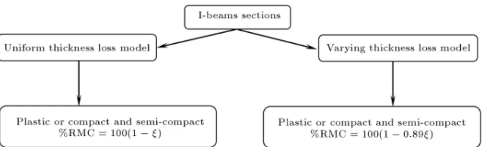
%RMC = 100(1 ): (13)
For varying thickness loss model sections, substituting Equation 11 into Equation 12 gives the %RMC of plastic and compact corrosion damaged sections as:
%RMC = 100[1 (1 !)]; (14)
where:
! = tNh2W=8
ZXN : (15)
For a minimum of %RMC (Equation 14), ! must be the minimum. By analyzing the sections, it was found that the minimum of ! can be obtained for the section that has the minimum values of the torsional index, x, and D=B ratio. The section that has the above properties was found to be IPE100 and the minimum value of ! was obtained as 0.1074. Substituting the above minimum value of ! into Equation 14 gives the minimum of %RMC of plastic and compact sections as:
min(%RMC) = 100(1 0:89): (16)
Therefore, the %RMC of sections that are plastic or compact in their as-new condition and which remain the same for part or all of their service life will be a straight line with a slope of approximately -1.0 for uniform thickness loss model sections and -0.89 for varying thickness loss model sections. Equations 13 and 16 may be used as the minimum curves for estimating the %RMC of any sections that are plastic or compact in both their as-new and corrosion damaged conditions.
Semi-Compact Sections
For semi-compact sections, the elastic modulus of the sections about the relevant axis is used for the moment capacity. The elastic modulus, SX, may be expressed
in terms of the plastic modulus, ZX, and the shape
factor, SF, as follows:
SX = ZX=SF: (17)
For corrosion damaged I-sections, the Shape Factor `SF' may be assumed as constant for all of their service life. If Equation 17 is substituted into Equations 4a and 4b, the following relations are obtained for the moment capacity of semi-compact sections:
For corrosion damaged sections:
McC = PyZxC=SF: (18a)
For as-new sections:
McN = PyZxN=SF: (18b)
Substituting Equations 18a and 18b into Equation 5 gives the %RMC of corrosion damaged semi-compact sections as:
%RMC = 100
ZXC
ZXN
Figure 3. Procedures for predicting the %RMC of corroded I-beam.
Equation 19 is identical to Equation 12, therefore, Equations 13 and 16 may still be used as the minimum curves to estimate the %RMC of semi-compact sections that remain in this class, even in their corroded state. The relations obtained from the proposed as-sessment method that give the remaining moment capacity of I-beam sections manufactured in Iran are summarized and shown as a owchart in Figure 3. The results of this research will help the practicing engineer make fast and reliable decisions regarding the remaining moment capacity of corrosion damaged I-beams.
CONCLUSIONS
For the assessment of the remaining moment capac-ity of corrosion damaged I-beams, a simple method has been proposed, namely, the simple assessment method. This method gives the quantitative rela-tionship between the magnitude of structural defects (loss of thickness) and the corresponding remaining moment capacity (expressed as percentage of the as-new strength) of corrosion damaged beams. This assessment method, which gives considerably reliable estimates of the remaining capacity of corrosion dam-aged I-beams, is easy to use, without the need for any lengthy calculation. In particular, the equations obtained in the simple assessment method will be more eective in assessing the capacity of corrosion damaged I-beams; they readily give the estimates of percentage remaining capacity if the thickness losses of the element are known. It is believed that this method will be benecial in terms of cost and safety. In addition, this method may be used to identify the weaker members whose capacities are closer to the service loads. This assessment method will help the practicing engineer make fast and reliable decisions regarding the future of corrosion damaged I-beams.
REFERENCES
1. Rahgozar, R. \Fatigue endurance of steel structures subjected to corrosion", PhD Thesis, Department of Civil Engineering, University of Bristol, UK (1998).
2. Kayser, J.R. \The eects of corrosion on the reliability of steel girder bridges", PhD Thesis, Department of Civil Engineering, University of Michigan, USA (1988). 3. Kulicki, J.M., Prucz, Z., Sorgenfrei, D.F. and Mertz, D.R. \Guidelines for evaluating corrosion eects in existing steel bridges", National Cooperative Highway Research Program Report 333, NCHRP, USA (1990). 4. Scully, J.C. \The fundamentals of corrosion", 3rd Ed.,
Pergamon Press Ltd., Oxford, England (1990). 5. Koch, G.H., Brongers, M.P.H., Thompson, N.G.,
Virmani, Y.P. and Payer, J.H. \Corrosion cost and preventive strategies in the United States", Report. No. FHWA-RD-01-156, Oce of Infrastructure Research and Development, Federal Highway Administration (2002).
6. Rahgozar, R. and Smith, J.W. \Fatigue endurance of steel structures subjected to pitting corrosion", Proceeding of Fourth International Conference on Civil Engineering, Sharif University of Technology, Tehran, Iran, pp. 237-246 (1997).
7. Gallon, M.J. \ICI engineering, managing structural corrosion in chemical plants", New Steel Construction, UK (1993).
8. Fontana, M.G., Corrosion Engineering, McGraw Hill Book Company, New York, Third Ed. (1987). 9. Kayser, J.R. and Nowak, A.S. \Evaluation of corroded
steel bridges", Structures Congress Related to Bridge and Transmission Line Structures, American Society of Civil Engineers, Orlando, Florida, pp. 35-47 (1987). 10. Kitagawa, H., Tsuji, K., Hisada, T. and Hashimoto Y. \An analysis of random pits in corrosion fatigue: A statistical three-dimensional evaluation of an irregu-larly corroded surface", Corrosion Fatigue: Mechanics, Metallurgy, Electrochemistry and Engineering, ASTM STP 801, Crooker, T.W. and Leis, B.N., Eds., pp. 147-158 (1983).
11. Sadeghi, J.M. and Fathali, M. \Deterioration analysis of concrete bridges under inadmissible loads from the fatigue point of view", Scientia Iranica, 14(3), pp. 185-192 (2007).
12. Rahgozar, R. \Remaining capacity assessment of cor-rosion damaged beams using minimum curves", Jour-nal of ConstructioJour-nal Steel Research, Elsevier, 65, pp. 299-307 (2009).
13. Kayser, J.R. and Nowak, A.S. \Capacity loss due to corrosion in steel-girder bridges", ASCE, Journal of Structural Engineering, 115, pp. 1525-1537 (1989).
BIOGRAPHIES
Yasser Shari is a PhD student of structural engi-neering at the University of Kerman, and an academic member of the civil engineering department of Vali-e-Asr University of Rafsanjan in Iran. His areas of research are reinforced concrete structures, behavior of tall buildings, corrosion in steel structures and structural mechanics in association with limit states and risk-based approaches. He is a recipient of the John Wiley outstanding paper award as coauthor of
the paper \The Structural Design of Tall and Special Buildings", in 2009. He is also author or coauthor of over 20 papers published in journals and presented at conferences.
Reza Rahgozar is Associate Professor in the civil engineering department of the University of Kerman, in Iran. His areas of research are retrotting of steel and reinforced concrete bridges, corrosion in steel structures, behavior of tall buildings, and the fatigue life of bridges. Dr Rahgozar is the recipient of the John Wiley outstanding paper award \The Structural Design of Tall and Special Buildings", in 2009. He is author or coauthor of over 110 papers published in journals and presented at conferences.