Sample Configuration: Avaya MultiVantage™ Software
with an Avaya™ S8300 Media Server Local Survivable
Processor and an Avaya™ G700 Media Gateway - Issue 1.0
Abstract
These Application Notes present a sample configuration for Avaya MultiVantage™ Software with an Avaya™ S8300 Media Server and an Avaya™ G700 Media Gateway. In the sample configuration, the Avaya S8300 Media Server is configured as a Local Survivable Processor (LSP). Avaya MultiVantage™ Software running on an Avaya™ S8700 Media Server provides primary service. The Avaya G700 Media Gateway registers with a TN799 CLAN circuit pack within an Avaya™ SCC1 Media Gateway, and this registration occurs over a WAN. If the Avaya G700 Media Gateway is unable to communicate with a CLAN in the remote SCC1, it will register with the Avaya S8300 Media Server LSP. The Avaya S8300 Media Server LSP will provide service to the devices connected to the Avaya G700 Media Gateway as well as any Avaya™ IP Telephones that register with the LSP. These notes illustrate how “IP network maps” and “IP network regions” can be used within the Avaya MultiVantage Software to manage intra-region (LAN) and inter-region (WAN)
1. Introduction
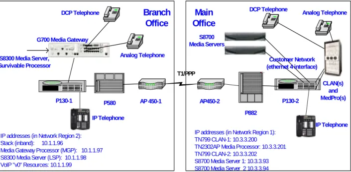
The network diagram in Figure 1 shows two offices. The office labeled “Branch Office”
contains an Avaya™ G700 Media Gateway with an Avaya™ S8300 Media Server, configured as a Local Survivable Processor (LSP). The office labeled “Main Office” utilizes Avaya
MultiVantage™ Software, Avaya™ S8700 Media Servers, and Avaya™ Single Carrier Cabinet (SCC1) and Avaya™ Multi-Carrier Cabinet (MCC1) Media Gateways (SCC1 connected
identically to the MCC1, but not pictured). The DHCP / TFTP servers used by the Avaya™ IP Telephones, and the private control network used exclusively for communication among the Avaya S8700 Media Servers and the TN2312 IP Services Interface (IPSI) Circuit Pack(s), are not shown.
The Avaya™ P130 Workgroup Switch, Avaya™ P580 MultiService Switch, and Avaya™ P882 MultiService Switch are used for the LAN connections within the offices. Access Point™ AP-450 IP Service Routers are used for the WAN (T1/PPP) connections between the two offices.
AP 450-1 P580 AP450-2 T1/PPP P130-1 P130-2 Branch Office Main Office P882
IP addresses (in Network Region 2): Stack (inband): 10.1.1.96
Media Gateway Processor (MGP): 10.1.1.97 S8300 Media Server (LSP): 10.1.1.98 VoIP "v0" Resources: 10.1.1.99
IP addresses (in Network Region 1): TN799 CLAN-1: 10.3.3.200
TN2302AP Media Processor: 10.3.3.201 TN799 CLAN-2: 10.3.3.202
S8700 Media Server 1: 10.3.3.93 S8700 Media Server 2 10.3.3.94
G700 Media Gateway
DCP Telephone DCP Telephone Analog Telephone
S8300 Media Server, Survivable Processor S8700 Media Servers CLAN(s) and MedPro(s) Customer Network (ethernet 4 interface) IP Telephone IP Telephone Analog Telephone
Figure 1: Survivable Avaya™ G700 Media Gateway, Controlled by Avaya™ S8700 Media Servers – Avaya Data Network Infrastructure
2. Software Versions
The table below shows the versions used for screen captures. Some of these are development versions; therefore, it is possible that small differences will be observed using the Generally Available versions of the Avaya MultiVantage Software and Avaya G700 Media Gateway.
Component Version
Avaya S8300 Media Server R011x.01.0.060.0 Avaya S8700 Media Servers R011x.01.0.060.0
P330 Stack Processor Resident in Avaya G700
3.8.2 Avaya G700 Media Gateway
Processor (MGP) 1 Microsoft DHCP Manager (Microsoft NT 4.00.1381 SP6) Version 4.0 Avaya IP Telephone 1.6
3. Configuration of the Avaya G700 Media Gateway
This section illustrates the steps necessary to configure the network identities of the following components within the Avaya™ G700 Media Gateway at the “branch office”:
• Avaya P330 stack processor (resident on the G700 Media Gateway) • Avaya G700 Media Gateway Processor (MGP)
• VoIP v0 Module resident on the Avaya G700 Media Gateway motherboard
It is assumed the reader has login and password credentials to access the Avaya G700 Media Gateway.
3.1. Configuring the P330 Stack on the Avaya G700 Media Gateway
Connect a COM port on a computer to the console port on the lower right corner of the Avaya G700 Media Gateway using a console port cable. Launch a terminal emulation program using appropriate connect parameters (i.e., COM 1, 9600 bps, no parity, 8 data bits, 1 stop bit, no flow control). Press the return key, and the login prompt will appear. Upon login, a welcome banner for the P330 similar to the following will be seen.Welcome to P330 SW version 3.8.2
While interacting with the P330 command line interface (CLI), help is available by using the keyword “help” at any point in a command. The help system is hierarchical. For example, “help”, “show help”, and ”show ip help” are all valid for displaying increasingly narrow help responses.
The format of the prompt is “Hostname-Stack number(mode)”. In the output shown below, the “hostname” is “Cajun_P330”, and the stack number is 1. Enter configure mode by issuing the command “configure”.
Assign IP parameters to the P330 stack processor using the “set interface” command. The syntax of the command is “set interface inband <vlan> <ip-addr> <netmask>”.
Cajun_P330-1(configure)# set interface inband 1 10.1.1.96 255.255.255.0 Management VLAN number set to 1
Interface inband IP address set.
You must reset the device in order for the change to take effect. Cajun_P330-1(configure)#
As the command response indicates, a reset must be performed for the change to take effect.
Cajun_P330-1(configure)# reset
This command will force a switch-over to the master module and disconnect your telnet session
*** Reset *** - do you want to continue (Y/N)? y Connection closed by foreign host.
Re-login using the login credentials previously supplied.
The “show interface inband” command can be used to verify the IP parameters.
Cajun_P330-1(configure)# show interface inband
Interface Name VLAN IP address Netmask --- ---- ---
---inband 1 10.1.1.96 255.255.255.0
Cajun_P330-1(configure)#
The IP route for the P330 stack will now be set, using the command syntax “set ip route
<destination> <gateway>”. It is not necessary to issue a reset after setting the IP route with the command below. In the example network, the gateway address is 10.1.1.1.
Cajun_P330-1(configure)# set ip route 0.0.0.0 10.1.1.1 destination = 0.0.0.0 gateway = 10.1.1.1
ROUTE NET TABLE
destination gateway flags Refcnt Use Interface
---0.0.0.0 10.1.1.1 3 0 0 se0
10.1.1.0 10.1.1.96 1 1 18 se0
127.1.1.0 127.1.1.1 1 5 580 se1
---ROUTE HOST TABLE
destination gateway flags Refcnt Use Interface
---127.0.0.1 127.0.0.1 5 2 9 lo0
---Cajun_P330-1(configure)#
The output of the prior command includes IP addresses that begin with 127. These addresses are used internally within the Avaya™ G700 Media Gateway.
3.2. Configuring the Avaya G700 Media Gateway Processor (MGP)
The next step is to interact with the command line interface (CLI) of the Avaya G700 Media Gateway Processor (MGP) to assign IP parameters. The MGP CLI can be accessed via the “session mgp” command; no new authentication is necessary. The MGP can also be accessed directly from the IP network once IP settings have been assigned to the MGP.Cajun_P330-1(configure)# session mgp
Enter configuration mode using the “configure” command.
Welcome to Media Gateway Processor FW version 01
MG-???-1(super)# configure MG-???-1(configure)#
The format of the prompt is “Hostname-Media Gateway number-Stack Number (mode)#”. In the examples shown, the hostname is MG. The hostname can be changed, if desired, using “set hostname”. The Media Gateway number will be shown as question marks until the gateway has registered with its controller. Once registered, the prompt will show the media gateway number assigned by the Avaya MultiVantage™ Software. The stack number is shown as 1 because this is a single (i.e., not stacked) Avaya G700 Media Gateway.
While interacting with the Avaya G700 MGP CLI, help is available by using the keyword help at any point in a command. For example, “help”, “show help”, and ”show interface help” are all valid for displaying increasingly narrow help responses.
The command “set interface mgp <vlan> <ip> <netmask>” can be used to set the IP parameters for the Avaya G700 Media Gateway Processor as follows:
MG-???-1(configure)# set interface mgp 1 10.1.1.97 255.255.255.0 The change will take effect after reboot.
MG-???-1(configure)#
As indicated, the user must issue a reset for the ip address assignment to take effect:
MG-???-1(configure)# reset mgp
This command will perform a hard reset. Do you want to continue (Y/N)? y
Connection closed by foreign host.
The MGP reset will end the “session mgp” session started previously. Wait a short time (e.g., one minute) to allow the MGP reset to proceed. Use the “session mgp” command to reconnect to the MGP CLI. Use the “configure” command to return to configure mode.
Verify the MGP configuration using the command “show interface mgp”. (Note that MAC Addresses have been removed or edited to show all zeroes throughout this document.)
MG-???-1(configure)# show interface mgp OPERATIONAL STATE: Currently in use
--INTERFACE SRC VLAN IP ADDRESS NETMASK MAC ADDRESS
--- --- ---- --- --- ---mgp S 1 10.1.1.97 255.255.255.0 00-00-00-00-00-00 MG-???-1(configure)#
The commands shown below assign and verify an IP route for the MGP. The command syntax is “set ip route <destination> <netmask> <gateway>”. The “0.0.0.0” addresses in the command imply a default gateway.
MG-???-1(configure)# set ip route 0.0.0.0 0.0.0.0 10.1.1.1 MG-???-1(configure)# show ip route mgp
DESTINATION MASK GATEWAY INTERFACE (F/C/U)
--- --- --- ---
---0.0.0.0 0.0.0.0 10.1.1.1 motfec0 (3/0/0)
10.1.1.0 255.255.255.0 10.1.1.97 motfec0 (101/0/0) MG-???-1(configure)#
3.3. Configuring the VoIP Module on the Avaya G700 Media Gateway
The next step assigns an IP address to the integral Voice over IP (VoIP) component resident on the Avaya G700 Media Gateway motherboard. This VoIP component is identified as “voip v0” to differentiate it from any (functionally equivalent) MM760 VoIP Media Modules installed in the media module bays (v1-v4). For readers familiar with VoIP on DEFINITY® IP Enabled Communication Servers, the VoIP v0 has a function analogous to the TN2302AP IP Media Processor circuit pack. The following command assigns an IP address to “voip v0”. The VoIP v0 will use the VLAN and NETMASK already set for the MGP.MG-???-1(configure)# set interface voip v0 10.1.1.99 MG-???-1(configure)#
The following command can be used to verify the VoIP v0 interface configuration.
MG-???-1(configure)# show interface voip v0 OPERATIONAL STATE: Currently in use
--INTERFACE SRC VLAN IP ADDRESS NETMASK MAC ADDRESS
--- --- ---- --- --- ---voip-v0 S 1 10.1.1.99 255.255.255.0 00-00-00-00-00-00 MG-???-1(configure)#
Before exiting the MGP, use the “show system” command, and write down the reported serial number (shown in bold). This serial number will be required when the media gateway is added at the Avaya S8700 Media Server SAT administration interface. (The output of this command has been abridged for brevity in presentation.)
MG-???-1(configure)# show system System Name : Branch office System Location: Sample Location System Contact : Sample Contact
Serial No : 01DR12310250
Model No : G700
4. Survivable Configuration of the Avaya™ S8300 Media
Server
This section presents configuration steps for the Avaya S8300 Media Server installed within the Avaya G700 Media Gateway in the branch office. It is assumed that an appropriate license file (for a local survivable processor) and an Avaya authentication file have been installed on the server, and that login and password credentials are available to the reader.
The IP identity of the Avaya S8300 Media Server is configured using a Web interface. While details of the web interface are beyond the scope of this document, a few pertinent procedures and screens are presented here.
To access the web interface, connect a computer to the services port of the Avaya S8300 Media Server, located in slot 1 on the left side of the Avaya G700 Media Gateway. The services port uses the pre-configured IP address 192.11.13.6 with mask 255.255.255.252. Configure the computer’s IP address as 192.11.13.5 with mask 255.255.255.252. Connect the computer’s Ethernet interface to the services port with a crossover Ethernet cable. Launch a web browser, turn proxies off, and connect to the URL http://192.11.13.6 Supply appropriate login and password credentials when prompted to do so.
After login, a main menu is presented along the left hand side. Click “Configure Server” from the lower left of this main menu. The instructions on the web screens are self-explanatory, and the relevant screen for IP address assignment is shown below.
On the screen presented after selecting “Continue”, the Avaya S8300 Media Server is configured as a survivable processor, whose primary controller is an Avaya S8700 Media Server. The IP addresses of the duplex S8700 Media Servers are 10.3.3.93 and 10.3.3.94 in this example configuration (i.e., these are the customer network, Ethernet 4, addresses assigned to the S8700 Media Servers).
The Avaya S8300 Media Server accepts translations from the S8700 Media Server. It is not necessary to access the Avaya S8300 Media Server SAT to enter translation information. Indeed, translations are prohibited from being saved from the Avaya S8300 Media Server SAT, when configured as a local survivable processor.
5. Configuration of the Avaya™ S8700 Media Server
This section presents configuration steps for the Avaya S8700 Media Server located in the main office. The procedures for configuring the TN2312 IPSI circuit packs and the private control network(s) linking the Avaya S8700 Media Servers to the IPSIs are not presented here, as this is not the focus of the application note. It is assumed that appropriate license files and
authentication files have been installed on the S8700 Media Servers, and that login and password credentials are available to the reader.
5.1. Configuring the Ethernet Interfaces of the S8700 Media Server
The Avaya S8700 Media Server is configured using a Web interface that is similar to the Avaya S8300 Media Server interface illustrated previously. To access the web interface, connect a computer to the services port of one of the Avaya S8700 Media Servers. (Each S8700 Media Server is configured separately.) When viewing the rear of the S8700 Media Server, the services port is the port labeled with a “2” on the left hand side (logical numbering begins with zero, so this port is referred to as Ethernet 1 in the web screens). The services port uses thepre-configured IP address 192.11.13.6 with mask 255.255.255.252. Configure the computer’s IP address as 192.11.13.5 with mask 255.255.255.252. Connect the computer’s Ethernet interface to the services port with a crossover Ethernet cable. Launch a web browser, turn proxies off, and connect to the URL http://192.11.13.6 Supply appropriate login and password credentials when prompted to do so.
After login, a main menu is presented along the left hand side. Click “Configure Server” from the lower left of this main menu.
The Avaya S8700 Media Server has multiple IP interfaces, and the default meanings for the IP interfaces were used in this sample configuration. The screens presented here are primarily intended to illustrate the IP addresses used by the S8700 Media Server to communicate with the S8300 Media Server configured as a Local Survivable Processor. This communication occurs using those addresses labeled Ethernet 4, “Corporate LAN.” Communication over this interface includes the synchronization of system translation information from the S8700 Media Server to the S8300 Media Server. This interface may also be used for other purposes, such as system administration from points on the customer’s network. The IP addresses assigned in this example are 10.3.3.93 and 10.3.3.94 as shown. The IP address assigned to the active server (10.3.3.95) can be used to connect to the currently active server, without needing to know in advance which one of the two servers is active. System administration is performed on the active server.
While not the focus of these notes, the other interface definitions can also be seen in the screen captures. The private control network(s) connecting the IPSI circuit packs with the Avaya S8700 Media Servers use control network A and B on Ethernet interfaces 0 and 3 respectively.
Ethernet 1 is dedicated to the services port. Ethernet 2 is a private “duplication” link (using a cross-over Ethernet cable) between the two S8700 Media Servers. Communication over this link includes arbitration of the active / standby status based on the health of the two servers.
5.2. Controlling Intra-office and Inter-Office VoIP Behavior
In this sample configuration, assume the customer has the following VoIP objectives:• At the main office as well as the branch office, intra-office VoIP communications should use G.711MU. This optimizes for voice quality and efficient use of IP media processing resources for VoIP on the LAN.
• Inter-office VoIP communications should utilize G.729A. This optimizes for efficient use of bandwidth over the WAN between the offices.
• Calls between IP entities should utilize “shuffling” for direct communication where possible. Shuffling to direct connections makes efficient use of IP media processing resources and can also improve voice quality, since fewer transcodings are necessary. The Avaya MultiVantage™ Software enables the achievement of these objectives by configuring the main office entities and remote office entities in different “IP network regions.” IP network regions can be used to define various IP properties, including the codec set to be used within the network region, and the codec set to be used for communication between a network region and other interconnected regions. A (new) feature of the Avaya MultiVantage Software enables the assignment of IP nodes to network regions via an “IP network map”. For example, in our configuration, the network map will allow an IP telephone located in the branch office to be associated with the same network region as the Avaya G700 Media Gateway in the branch office, despite the fact that this IP telephone will be registered with a CLAN physically located in the main office (i.e., under normal operating conditions). The IP network map can assign an IP network region based on IP address, and the IP network region form allows a “location” to be associated with the region. Although not a focus of these application notes, the IP network map is also used to ensure that an IP telephone located at a branch office, but registered to a CLAN at the main office, will receive appropriate E911 routing, trunk routing (e.g., preferentially
selecting trunks from the same physical location), and time zone offset adjustments, where applicable.
The next series of steps are performed through the System Access Terminal (SAT) interface. When prompted, supply an appropriate login and password to login to the SAT. There are a variety of ways to access the SAT login prompt. These include, but are not limited to:
• Using “telnet 192.11.13.6 5023” from the computer connected to the services port of the Avaya S8700 Media Server. Using 5023 as an argument to telnet brings the user directly to the SAT without presenting the Linux command line interface. If 5023 is omitted from the telnet command, simply type “sat” from the Linux prompt.
• Using telnet to the IP address assigned to the S8700 Media Server from the customer’s network (e.g., telnet 10.3.3.95 5023). This approach would not use the direct connection to the services port of the Avaya S8700 Media Server, but rather could be performed from a computer connected to the data network with access to 10.3.3.0/24.
In this document, Avaya S8700 Media Server SAT screens are shown with a gray background to help distinguish them from the unshaded presentation of the Avaya G700 Media Gateway
screens. Screen shots have been edited (e.g., to add bold formatting to pertinent fields) and abridged for brevity of presentation.
Using “change ip-network-map” as shown below, all addresses in the range 10.1.1.1 through 10.1.1.255 are assigned to network region 2. The subnetting is such that all nodes with these IP addresses are located at the branch office. All addresses in the range 10.3.3.1 through 10.3.3.255 are assigned to network region 1, and these nodes are located at the main office. This simple approach suffices in this example, but the ip-network-map is flexible and can accommodate more complex networks.
change ip-network-map Page 1 of 32
IP ADDRESS MAPPING Subnet
From IP Address (To IP Address or Mask) Region
10 .1 .1 .1 10 .1 .1 .255 2
10 .3 .3 .1 10 .3 .3 .255 1
. . . .
. . . .
The output of “change ip-network-region 1” that follows shows that region 1 is configured to use codec set 1 (page 1). The matrix shown on page 2 defines how the region being administered (region 1) interconnects with other regions, an important consideration in the design. To allow communications between entities (e.g., IP Telephones, Media Gateway VoIP resources, etc.) in the region being administered and entities in other regions, it is necessary to enter a codec set in the appropriate position in this matrix. In this example, network region 1 interconnects with network region 2 using codec set 2. A blank in the matrix implies no interconnection with the corresponding region. The position in the matrix corresponding to intra-region communication is automatically populated with the codec set from page 1. The position in the matrix controlling region 1 to region 2 communication has been edited to add the number 2, meaning codec set 2 should be used to interconnect region 1 with region 2.
Direct IP-IP audio connections, often referred to as “shuffling,” are enabled here for the region. Shuffling must also be enabled system-wide (page 12 of “display system-parameters features”). As can be observed, the network region form can also be used to configure QoS parameters, which are not the subject of this application note.
change ip-network-region 1 Page 1 of 2 IP Network Region
Region: 1
Name: Main Office
Audio Parameters Direct IP-IP Audio Connections? y
Codec Set: 1 IP Audio Hairpinning? y
Location: 1
UDP Port Range RTCP Enabled? y
Min: 2048 RTCP Monitor Server Parameters
Max: 3028 Use Default Server Parameters? y
DiffServ/TOS Parameters Call Control PHB Value: 34
VoIP Media PHB Value: 46
BBE PHB Value: 43 Resource Reservation Parameters
RSVP Enabled? n 802.1p/Q Enabled? n
change ip-network-region 1 Page 2 of 2
Inter Network Region Connection Management
Region (Group Of 32) 1 2 3 4 5 6 7 8 9 0 1 2 3 4 5 6 7 8 9 0 1 2 3 4 5 6 7 8 9 0 1 2 001-032 1 2 033-064 065-096 … … … … (to 250)
The “change ip-codec-set n” command is used to define an easily referenced set n, where the set contains a list of (seven) audio codecs, ordered by preference. For simplicity in presentation, G.711MU is shown as the only codec in set 1. Since IP network region 1 uses ip-codec-set 1, all communications requiring VoIP within IP network region 1 (the main office) will use G.711MU.
change ip-codec-set 1 Page 1 of 1
IP Codec Set Codec Set: 1
Audio Silence Frames Packet
Codec Suppression Per Pkt Size(ms)
1: G.711MU n 2 20
2: 3:
………… (to 7)
The command “change ip-codec-set 2” is used below to define a codec set to be referenced when G.729 with silence suppression is desired. Since IP network region 1 (the main office) has been configured to use ip-codec-set 2 for communications with IP network region 2 (the branch office), this inter-office communication will use G.729 for efficient use of bandwidth over the WAN connecting the two offices.
change ip-codec-set 2 Page 1 of 1 IP Codec Set
Codec Set: 2
Audio Silence Frames Packet
Codec Suppression Per Pkt Size(ms)
1: G.729 y 2 20
2: 3:
………… (to 7)
Similarly, “change ip-network-region 2” is used to define the VoIP behavior for network region 2, corresponding to the branch office. Like network region 1, network region 2 uses codec set 1 (i.e., G.711MU) for intra-region (intra-branch) communications, and allows direct IP-IP audio connections. The matrix on page 2 of the form shows that network region 2 will use codec set 2 (i.e., G.729) when communicating with network region 1 (the main office).
change ip-network-region 2 Page 1 of 2
IP Network Region Region: 2
Name: Branch Office
Audio Parameters Direct IP-IP Audio Connections? y
Codec Set: 1 IP Audio Hairpinning? y
Location: 2
UDP Port Range RTCP Enabled? y
Min: 2048 RTCP Monitor Server Parameters
Max: 3028 Use Default Server Parameters? y
DiffServ/TOS Parameters Call Control PHB Value: 34
VoIP Media PHB Value: 46
BBE PHB Value: 43 Resource Reservation Parameters
RSVP Enabled? n 802.1p/Q Enabled? n
change ip-network-region 2 Page 2 of 2
Inter Network Region Connection Management
Region (Group Of 32) 1 2 3 4 5 6 7 8 9 0 1 2 3 4 5 6 7 8 9 0 1 2 3 4 5 6 7 8 9 0 1 2 001-032 2 1 033-064 065-096 … … … … (to 250)
The media gateway is added via the command “add media-gateway x” where x will be the Media Gateway number. This number will appear in the Avaya G700 MGP CLI command prompt, once the gateway has registered. The media gateway will be assigned to network region 2, the region used for the branch office in this example.
The Identifier field (in bold) must be populated with the Serial Number of the Avaya G700 Media Gateway. This is the serial number the reader was asked to note using the “show system”
that is not assigned via the SAT. The IP address field will contain data after the media gateway has registered with its controller. The following snapshot of the “change media-gateway 2” command was issued after the Avaya G700 Media Gateway had registered.
change media-gateway 2 Page 1 of 1
MEDIA GATEWAY Number: 2
Name: S8300 LSP Identifier: 01DR12310250
IP Address: 10 .1 .1 .97 MAC Address: 00:00:00:00:00:00 (edited)
Network Region: 2 Location: 2
Site Data: Registered? y
Slot Module Type
V1: icc
V2: dcp
V3: analog
V4: ds1
Station administration uses the same procedures used on DEFINITY® IP Enabled
Communication Servers. The following “change station” screenshot is provided to illustrate port addressing for Avaya™ G700 Media Gateway ports. The port 002v201 (shown in bold below) has the following meaning. The 002 is the media gateway number. When entering data in a port field, you need only type 2v201. The “v2” is the slot location (i.e., media module bay number) within the gateway, and the “01” is the port on this media module. Note that the “change media-gateway 2” command (shown above) reports a DCP media module (MM712) in slot 2.
change station 41900 Page 1 of 4
STATION
Extension: 41900 Lock Messages? n BCC: 0
Type: 6402D Security Code: TN: 1
Port: 002V201 Coverage Path 1: COR: 1
Name: Sample DCP Coverage Path 2: COS: 1
Hunt-to Station:
6. DHCP Configuration and IP Telephone Registration
Considerations
Avaya™ IP Telephones can acquire a list of H.323 gatekeepers or controllers using DHCP. In configurations that include survivable processors, the DHCP list will contain CLAN address(es) as well as the IP address of the S8300 Media Server functioning as a survivable processor. In this sample configuration, for the DHCP scope corresponding to the Avaya IP Telephones in the branch office, MCIPADD will contain 10.3.3.200 (CLAN), 10.3.3.202 (CLAN), and
10.1.1.98 (S8300 LSP) in option 176. If the Avaya IP Telephones at the branch office are unable to communicate with the CLANs in the main office, they will attempt to register with the Avaya S8300 Media Server LSP at the branch office. In this example, the DHCP list served to the Avaya IP Telephones in the branch office is the same as the G700 Media Gateway controller list
(Section 7), but this need not be the case in general. For example, the DHCP MCIPADD string may even include gatekeeper addresses corresponding to other call processing servers (i.e., other switches).
Although details of IP telephone registration and recovery procedures are beyond the scope of this document, a description of a common scenario may be instructive. Upon reset, Avaya™ IP Telephones will contact (via Gatekeeper Request, abbreviated GRQ) the first gatekeeper
appearing in the MCIPADD list. The MultiVantage™ Software will reply (via Gatekeeper Confirm, abbreviated GCF), and the response indicates the IP address the telephone should use to attempt to register. The IP address chosen by the MultiVantage Software in this step may be the same address used for initial contact, or an alternate CLAN address, different from the address used for initial contact. This capability, referred to as CLAN load balancing, enables the MultiVantage Software to distribute registrations across CLANs in the same network region. The phone then attempts to register (via Registration Request, abbreviated RRQ) with the IP address supplied by the MultiVantage Software in the previous step. Assuming the registration is allowed, the MultiVantage Software will register the phone, and also send to the phone (via Registration Confirm, abbreviated RCF) a list of alternate gatekeeper addresses. This list of alternate gatekeeper addresses can contain CLANs in the same network region as well as CLANs from any interconnected regions. (Future releases of the MultiVantage Software will be able to provide LSP addresses as well as CLAN addresses in the list of alternate gatekeepers returned to the telephone). Using these procedures, some of the Avaya IP Telephones in our example will register to the CLAN with IP address 10.3.3.200, and some will register to the CLAN with IP address 10.3.3.202. Examples of status screens showing the registration status are shown in Section 9.
If a registered IP telephone loses connectivity to its current gatekeeper, it will attempt recovery automatically. Again, details on the recovery procedures are beyond the scope of this document. Generally, the IP telephone will use the DHCP list and the list of alternate gatekeepers provided by the MultiVantage Software to attempt to re-register the telephone. Assuming at least one of the CLAN IP addresses is accessible, the IP telephone will have the opportunity to re-register
with the Avaya S8300 Media Server LSP appearing in the DHCP list, the registration may be rejected by the LSP, if an Avaya G700 Media Gateway has not registered with the LSP before the telephone. This reduces the possibility that an IP telephone will register with the LSP before G700 Media Gateway VoIP resources are available. Generally, the design also aims to minimize the possibility that an IP telephone will register successfully with an LSP if there are CLANs from the primary controller available to provide service.
7. The Avaya G700 Media Gateway Controller List
The Avaya™ G700 Media Gateway maintains a statically provisioned list of controllers. In our sample configuration, three IP addresses will be configured. The first two addresses will be the addresses of CLAN circuit packs physically located in the SCC1 Media Gateway in the main office. The third address will be the address of the Avaya™ S8300 Media Server (LSP) within the Avaya G700 Media Gateway in the branch office.
Log-in to the MGP CLI as explained in Section 3. The command “set mgc list” can be used to set the controller IP addresses as follows:
MG-???-1(configure)# set mgc list 10.3.3.200, 10.3.3.202, 10.1.1.98 MG-???-1(configure)#
The command “show mgc list” displays the contents of the controller list.
MG-???-1(configure)# show mgc list
CONFIGURED MGC HOST DHCP SPECIFIED MGC HOST ---
---10.3.3.200 Not Available
--10.3.3.202 Not Available
--10.1.1.98 Not Available
---- Not Available ---- Not Available --MG-???-1(configure)#
The procedures shown above assume the controller list was empty at the start. The “clear mgc list” command can be used to remove unwanted entries from the list.
Once the Avaya G700 Media Gateway has registered with its controller, the prompt will show the media gateway number assigned by the active controller. The command “show mgc” displays the status of the H.248 link to the controller. The prompt shown below now includes the media gateway number assigned by the Avaya S8700 Media Server upon registration of the gateway. The “active controller” in this output shows the CLAN or S8300 Media Server to which the G700 Media Gateway is currently registered.
MG-002-1(configure)# show mgc CALL CONTROLLER STATUS
---Registered : YES
Active Controller : 10.3.3.200 H248 Link Status : UP
H248 Link Error Code: 0x0 MGC List Management : Static
CONFIGURED MGC HOST DHCP SPECIFIED MGC HOST ---
---10.3.3.200 Not Available
--10.3.3.202 Not Available
--10.1.1.98 Not Available
---- Not Available ---- Not Available
--The Avaya G700 Media Gateway will now be programmed with information relevant to its recovery process. The “set mgp reset-times help” command is illustrated below to show the commands, which will be described briefly below.
MG-002-1(configure)# set mgp reset-times help set mgp reset-times commands:
---set mgp re---set-times primary-search Sets the MGP primary search timer
set mgp reset-times total-search Sets the MGP total search timer
set mgp reset-times transition-point Sets the MGP entry point
The media gateway controller list has been configured with the addresses of two CLAN boards (i.e., “primary addresses”) as well as the address of the Avaya S8300 Media Server serving as a local survivable processor. The following command instructs the Avaya G700 Media Gateway of the “transition point” in the media gateway controller list. Typically, when controlled by an S8700 Media Server, the number used will be the number of CLAN addresses in the media gateway controller list.
MG-002-1(configure)# set mgp reset-times transition-point 2 MG-002-1(configure)#
The primary search time is the time (in minutes) that the MGP will attempt to connect with those addresses in the controller list up to and including the transition point, before moving on to try to connect to addresses beyond this transition point. In the sample configuration, the set command was not used to change the primary search interval. Therefore, the default value, 2 minutes, was retained. In lieu of the “set” command output, find below the output of the corresponding help.
MG-002-1(configure)# set mgp reset-times primary-search help set mgp reset-times primary-search command:
---Usage: set mgp reset-times primary-search <minutes>
<minutes> - Number of minutes for the primary search timer. Values allowed are from 1 to 60.
Example: set mgp reset-times primary-search 15
The total search time is the time (in minutes) that the MGP will attempt to connect with all addresses in the controller list, before the MGP will perform a hard reset. In the sample
configuration, the set command was not used to change the total search interval. Therefore, the default value, 30 minutes, was retained. In lieu of the “set” command output, find below the output of the corresponding help.
MG-002-1(configure)# set mgp reset-times total-search help set mgp reset-times total-search command:
---Usage: set mgp reset-times total-search <minutes>
<minutes> - Number of minutes for the total search timer. Values allowed are from 1 to 60.
Example: set mgp reset-times total-search 30
The following command summarizes the recovery parameters.
MG-002-1(configure)# show mgp recovery MGP RECOVERY TIMES
---Primary Search : 2
Total Search : 30 Transition Point: 2
These commands provide control over the recovery behavior. For example, if network outages of more than 2 minutes are anticipated, the primary search time can be lengthened to avoid the Avaya™ G700 Media Gateway registering with the LSP before the network recovers. On the other hand, if it is desirable to have the G700 Media Gateway fail-over to the LSP more quickly when the CLAN addresses are unreachable, the primary-search timer can be reduced. There is nothing to prevent the administrator from including an LSP address within the transition point normally associated with the primary addresses.
8. Basic Troubleshooting
While advanced troubleshooting is beyond the scope of this document, several basic commands and topics will be illustrated here.
If the Avaya™ G700 Media Gateway is unable to register with the CLAN addresses in the Avaya G700 Media Gateway’s controller list, check IP connectivity between the MGP and the CLANs, and check the Serial Number administration.
To check IP connectivity, the CLI of the MGP (see section 3) provides the capability to ping from the MGP (or VoIP engine) to any IP address. Below, ping commands are used to show that the Avaya G700 Media Gateway Processor (MGP) can ping the IP addresses assigned to the CLAN circuit packs in the media gateway controller list.
MG-002-1(configure)# ping mgp 10.3.3.200 PING 10.3.3.200: 56 data bytes
64 bytes from 10.3.3.200: icmp_seq=0. time=5. ms 64 bytes from 10.3.3.200: icmp_seq=1. time=0. ms 64 bytes from 10.3.3.200: icmp_seq=2. time=0. ms 64 bytes from 10.3.3.200: icmp_seq=3. time=0. ms 64 bytes from 10.3.3.200: icmp_seq=4. time=0. ms ----10.3.3.200 PING
Statistics----5 packets transmitted, Statistics----5 packets received, 0% packet loss round-trip (ms) min/avg/max = 0/1/5
MG-002-1(configure)#
MG-002-1(configure)# ping mgp 10.3.3.202 PING 10.3.3.202: 56 data bytes
64 bytes from 10.3.3.202: icmp_seq=0. time=5. ms 64 bytes from 10.3.3.202: icmp_seq=1. time=0. ms 64 bytes from 10.3.3.202: icmp_seq=2. time=0. ms 64 bytes from 10.3.3.202: icmp_seq=3. time=0. ms 64 bytes from 10.3.3.202: icmp_seq=4. time=0. ms ----10.3.3.202 PING
Statistics----5 packets transmitted, Statistics----5 packets received, 0% packet loss round-trip (ms) min/avg/max = 0/1/5
If ping fails, ensure that the configuration steps detailed in previous sections have been
performed properly, and that routing has been established properly across the WAN. Ensure that a crossover Ethernet cable has been used to connect one of the ports in the lower center of the Avaya G700 Media Gateway to the external data network switch.
It is also possible to ping from the Avaya™ S8700 Media Server SAT. The following is an example of a ping from the CLAN in slot 1A05 to the G700 Media Gateway Processor.
ping ip-address board 01A05 10.1.1.97 PING RESULTS
End-pt IP Port Port Type Result Time(ms) Error Code
10.1.1.97 01A0517 ETH-PT PASS 10
If basic connectivity exists as evidenced by a successful ping, but the Avaya G700 Media Gateway will not register, make sure that the Serial Number entered as the “Identifier” using the
number of the Avaya G700 Media Gateway. The following command available from the Avaya S8700 Media Server SAT provides a convenient way to view the identifier and registration status of all administered gateways.
list media-gateway
MEDIA-GATEWAY REPORT
Number Name Identifier IP Address Registered?
2 S8300 LSP 01DR12310250 10 .1 .1 .97 y
The serial number of the Avaya G700 Media Gateway can be obtained using the “show system” command from the MGP CLI (as shown in section 3). Use the “change media-gateway”
command from the Avaya S8700 Media Server SAT interface to correct the serial number if a mismatch is discovered.
If the Avaya G700 Media Gateway is unable to register with the Avaya S8300 Media Server when fail-over to the LSP is expected, one cause could be the absence of translation data on the S8300 Media Server. If the S8300 Media Server LSP has not accepted translations that include a Media Gateway with the proper serial number, the G700 Media Gateway will be unable to register. The S8700 Media Server can be triggered to synchronize translation information with the S8300 Media Server LSP using the SAT command “save translation”. If “save translation” had indicated “success”, but absence of translations is still suspected, it is possible that the S8700 Media Server was not aware of the S8300 LSP when translations were saved. (Advanced readers may wish to check the timestamp of the translation files on the S8300 Media Server as well as the content of the lspList on the S8700 Media Server.) Successful translation synchronization requires the Avaya™ S8300 and Avaya S8700 Media Server’s “Configure Server” steps from the web interface to be performed properly. Translation synchronization uses the Ethernet 4 interface of the S8700 Media Server and the IP address of the S8300 Media Server LSP. The Web interface of the S8300 Media Server can be used to ping from the S8300 Media Server LSP to the IP addresses assigned to the S8700 Media Server’s Ethernet 4 ports. An example is shown below.
If IP telephones are unable to register with the Avaya S8300 Media Server when fail-over to the LSP is expected, verify that the DHCP configuration served to the phones includes the IP address of the S8300 Media Server.
If calls are not “shuffling” to direct IP-IP audio connections when expected, verify that shuffling is enabled system wide (i.e., page 12 of “display system-parameters features”), and also enabled for the devices expected to participate in the direct IP-IP audio connection. For stations, check page 2 of “display station x”. Verify that direct IP-IP audio connections are enabled on the network region form (“display ip-network-region x”).
The following verification section provides details on the status of connections that may also help the reader in troubleshooting.
9. Verify Connectivity
Verification of the configuration in these application notes included, but was not limited to: • Registration of Avaya™ 4612 IP Telephones at both the main office and the branch
office to the CLANs in the main office.
• Registration of the Avaya™ G700 Media Gateway to the CLANs in the main office. • Intra-office calls among DCP phones, analog phones, and Avaya 4612 IP Telephones
under normal operation. Intra-office calls requiring VoIP used G.711 on the office LAN. • Inter-office calls among DCP phones, analog phones, and Avaya 4612 IP Telephones
under normal operation. These calls utilized G.729A over the WAN.
• Forced interchange from the active to standby S8700 Media Server, to show that an interchange does not cause the G700 Media Gateway to lose registration with the CLAN.
• Forced failure of the first CLAN appearing in both the DHCP list and G700 Media Gateway controller list. The IP Telephones and G700 Media Gateway register with the second CLAN (10.3.3.202) in the test configuration.
• Forced failure, creating conditions where no CLAN is reachable for a sufficient time to automatically trigger the G700 Media Gateway and IP Telephones at the branch to
register with the S8300 LSP. The IP Telephones and ports connected to the G700 Media Gateway receive service from the S8300 Media Server LSP. Service from the LSP is not limited to basic telephony, but also includes access to MultiVantage™ Software features such as conference, bridging, etc.
• Fail-back of the G700 Media Gateway and IP Telephones at the branch to the CLANs controlled by the S8700 Media Server at the main, as directed by manual intervention on the S8300 Media Server LSP.
The following snapshots of status screens are presented to reinforce concepts presented earlier. The node names and IP interfaces shown below are referenced within the status screens. These commands were executed while S8700 Media Server 2, with IP address 10.3.3.94, was active.
change node-names ip Page 1 of 1
IP NODE NAMES
Name IP Address Name IP Address
default 0 .0 .0 .0 . . . g700-loc2-voipv 10 .1 .1 .99 . . . procr 10 .3 .3 .94 . . . s8300-lsp-loc2 10 .1 .1 .98 . . . scc1-clan 10 .3 .3 .200 . . . scc1-clan2 10 .3 .3 .202 . . . scc1-prowler 10 .3 .3 .201 . . . . . . . . . . .
( 7 of 7 administered node-names were displayed )
Use 'list node-names' command to see all the administered node-names
Use 'change node-names ip xxx' to change a node-name 'xxx' or add a node-name
change ip-interfaces Page 1 of 15
IP INTERFACES
Enable Net
Eth Pt Type Slot Code Sfx Node Name Subnet Mask Gateway Address Rgn y C-LAN 01A08 TN799 D scc1-clan2 255.255.255.0 10 .3 .3 .1 1 y C-LAN 01A05 TN799 D scc1-clan 255.255.255.0 10 .3 .3 .1 1 y MEDPRO 01A06 TN2302 scc1-prowler 255.255.255.0 10 .3 .3 .1 1
n 255.255.255.0 . . .
The following “status station” command was executed from the Avaya S8700 Media Server SAT while an intra-office call was connected. This intra-office call connects an Avaya™ 4612 IP telephone (extension 40500, IP address 10.3.3.85) and an analog telephone (port 1A1501) in the main office. Observe that the IP telephone has registered with the CLAN whose node name is scc1-clan (IP address 10.3.3.200). This intra-region call uses the TN2302 IP Media Processor circuit pack in slot 1A06 for conversion between analog and IP. The G.711MU codec is used for intra-office VoIP on the LAN.
status station 40500 Page 3 of 6 CALL CONTROL SIGNALING
Switch IP IP
Port Switch-end IP Addr:Port Set-end IP Addr:Port
IP Signaling: 01A0517 10. 3. 3.200 :1720 10. 3. 3. 85:4423
H.245:
Node Name: scc1-clan
Network Region: 1 1
AUDIO CHANNEL
Switch IP IP
Port Other-end IP Addr :Port Set-end IP Addr:Port
G.711MU Audio: 01A0601 10. 3. 3.201 :2312 10. 3. 3. 85:2404
Node Name: scc1-prowler
Network Region: 1 1
Audio Connection Type: ip-tdm Product ID: IP_Phone H.245 Tunneled in Q.931? does not apply
Registration Status: registered-authenticated
status station 40500 Page 6 of 6
CONNECTED PORTS
src port: S00001 src port: S00001
MP HP MP H
ip-start: 10. 3. 3. 85:2404
ip-end: 10. 3. 3.201:2312 01A0601
audio: G.711MU ss:off pkt:20ms
dst port: 01A1501 dst port:
The following “status station” command was executed from the Avaya S8700 Media Server SAT while an Avaya IP Telephone in the branch office is off-hook and listening to dial tone. Observe that the IP telephone (extension 40700, IP address 10.1.1.75) has registered over the WAN with the CLAN whose node name is scc1-clan (IP address 10.3.3.200). Even though the phone is registered to a CLAN defined to be in network region 1, the IP phone is in network region 2, reflecting the IP network map configuration. When an IP phone in network region 2 needs VoIP resources, the MultiVantage™ Software will use VoIP resources from the G700 Media Gateway, assigned to network region 2 via “add media gateway”. Observe that the “VoIP v0” IP Media Processing resources (IP address 10.1.1.99) are in use, and that the codec is G.711MU, which has been configured for use for intra-region communications over the LAN.
status station 40700 Page 3 of 4
CALL CONTROL SIGNALING
Switch IP IP
Port Switch-end IP Addr:Port Set-end IP Addr:Port
IP Signaling: 01A0517 10. 3. 3. 200 :1720 10. 1. 1. 75:4069
H.245:
Node Name: scc1-clan
Network Region: 1 2
AUDIO CHANNEL
Switch IP IP
Port Other-end IP Addr :Port Set-end IP Addr:Port
G.711MU Audio: 10. 1. 1. 99 :2058 10. 1. 1. 75:2770
Node Name: g700-loc2-voipv
Network Region: 2 2
Audio Connection Type: ip-tdm Product ID: IP_Phone H.245 Tunneled in Q.931? does not apply
The following “status station” command was executed from the Avaya S8700 Media Server SAT while an inter-office call was up between an Avaya 4612 IP telephone in the main office
(extension 40500, IP address 10.3.3.85) and an Avaya 4612 IP telephone in the branch office (extension 40700, IP address 10.1.1.75). Due to CLAN load balancing, the IP telephone with extension 40500 has registered with the CLAN whose node name is scc1-clan2 (IP address 10.3.3.202). Observe that “shuffling” has occurred, resulting in the desired direct IP-IP audio connection between the telephones from the two different network regions, using G.729A to conserve bandwidth over the WAN.
status station 40500 Page 3 of 5
CALL CONTROL SIGNALING
Switch IP IP
Port Switch-end IP Addr:Port Set-end IP Addr:Port
IP Signaling: 01A0817 10. 3. 3.202 :1720 10. 3. 3. 85:4069
H.245:
Node Name: scc1-clan2
Network Region: 1 1
AUDIO CHANNEL
Switch IP IP
Port Other-end IP Addr :Port Set-end IP Addr:Port
G.729A Audio: 10. 1. 1. 75 :2284 10. 3. 3. 85:2222
Node Name:
Network Region: 2 1
Audio Connection Type: ip-direct Product ID: IP_Phone H.245 Tunneled in Q.931? does not apply
Registration Status: registered-authenticated
status station 40500 Page 5 of 5
CONNECTED PORTS src port: S00001 src port: S00001 MP HP MP HP ip-start: 10. 3. 3. 85:2222 ip-end: 10. 1. 1. 75:2284
audio: G.729A ss:on pkt:20ms
dst port: S00000 dst port:
The following “status station” command was executed from the Avaya S8700 Media Server SAT while an inter-office call was up between an Avaya 4612 IP telephone in the branch office
(extension 40700, IP address 10.1.1.75) and an analog station in the main office (port 1a1501). The final configuration of this call includes a direct G.729A IP-IP audio connection between the IP telephone in the branch office and the TN2302 IP Media Processor in the main office. Since the call does not directly connect two IP telephones, it is shown as “ip-tdm”. However,
“shuffling” has occurred from the perspective of the media gateway, which no longer requires IP media processing resources for this call.
status station 40700 Page 3 of 6 CALL CONTROL SIGNALING
Switch IP IP
Port Switch-end IP Addr:Port Set-end IP Addr:Port
IP Signaling: 01A0517 10. 3. 3. 200 :1720 10. 1. 1. 75:4069
H.245:
Node Name: scc1-clan
Network Region: 1 2
AUDIO CHANNEL
Switch IP IP
Port Other-end IP Addr :Port Set-end IP Addr:Port
G.729A Audio: 01A0608 10. 3. 3.201 :2380 10. 1. 1. 75:2770
Node Name: scc1-prowler
Network Region: 1 2
Audio Connection Type: ip-tdm Product ID: IP_Phone H.245 Tunneled in Q.931? does not apply
Registration Status: registered-authenticated
status station 40700 Page 6 of 6
CONNECTED PORTS src port: S00000 src port: S00000 MP HP MP HP ip-start: 10. 1. 1. 75:2770 ip-end: 10. 3. 3.201:2380 01A0608
audio: G.729A ss:on pkt:20ms
dst port: 01A1501 dst port:
These final status screens illustrate the detailed connections for a three party conference call. The conference participants are extension 40500, an IP telephone (S00001) in Region 1,
extension 40700, an IP telephone (S00000) in Region 2, and 40600, an analog station using port 1A1501 in Region 1. As an aside, all participants dialed into this conference using the new MultiVantage™ Software Meet-me Conferencing feature.
From “status station 40500” note that the intra-office connection between the IP telephone
(10.3.3.85) and the TN2302 IP Media Processor circuit pack (1A06 / 10.3.3.201) uses G.711MU. The inter-office connection between the TN2302 IP Media Processor circuit pack and the IP telephone (10.1.1.75) at the branch office uses G.729A.
status station 40500 Page 6 of 6
CONNECTED PORTS
src port: S00001 src port: S00001
MP HP MP
HP
ip-start: 10. 3. 3. 85:2222 10. 3. 3. 85:2222
ip-end: 10. 3. 3.201:2136 01A0608 10. 3. 3.201:2136 01A0608
audio: G.711MU ss:off pkt:20ms G.711MU ss:off pkt:20ms
ip-start: 10. 3. 3.201:2140 01A0608 ip-end: 10. 1. 1. 75:2350
audio: G.729A ss:on pkt:20ms
From “status station 40700” note that the call has “shuffled” to a direct IP-IP G.729A audio connection between the station at the branch (IP 10.1.1.75) and the IP Media Processor Circuit Pack at the main (IP 10.3.3.201). Resources from the Media Gateway VoIP v0 are not in use for this call.
status station 40700 Page 6 of 6
CONNECTED PORTS
src port: S00000 src port: S00000
MP HP MP
HP
ip-start: 10. 1. 1. 75:2350 10. 1. 1. 75:2350
ip-end: 10. 3. 3.201:2140 01A0608 10. 3. 3.201:2140 01A0608
audio: G.729A ss:on pkt:20ms G.729A ss:on pkt:20ms
ip-start: 10. 3. 3.201:2136 01A0608 ip-end: 10. 3. 3. 85:2222
audio: G.711MU ss:off pkt:20ms
dst port: S00001 dst port: 01A1501
The output of “status station 40600” completes the connection presentation, again showing G.711MU on the LAN and G.729A on the WAN.
status station 40600 Page 4 of 4
CONNECTED PORTS
src port: 01A1501 src port: 01A1501
MP HP MP
HP
ip-start: 10. 3. 3.201:2136 01A0608 10. 3. 3.201:2140 01A0608
ip-end: 10. 3. 3. 85:2222 10. 1. 1. 75:2350
audio: G.711MU ss:off pkt:20ms G.729A ss:on pkt:20ms
dst port: S00001 dst port: S00000
10. Conclusion
As illustrated by these Application Notes, an Avaya™ S8700 Media Server located in a Main Office can provide primary service to an Avaya™ G700 Media Gateway located in a Branch Office. If the Avaya G700 Media Gateway is unable to communicate with the Main Office, the Avaya™ S8300 Media Server LSP can provide service to the devices connected to the Avaya G700 Media Gateway as well as any Avaya™ IP Telephones that register with the LSP. The Avaya MultiVantage™ Software allows the administrator to control the VoIP characteristics of intra-office and inter-office calls.
© 2002 Avaya Inc. All Rights Reserved.
Avaya and the Avaya Logo are trademarks of Avaya Inc. All trademarks identified by ® and ™ are registered trademarks or trademarks, respectively, of Avaya Inc. All other trademarks are the property of their respective owners. The information provided in these Application Notes is subject to change without notice. The configurations, technical data, and recommendations provided in these Application Notes are believed to be accurate and dependable, but are
presented without express or implied warranty. Users are responsible for their application of any products specified in these Application Notes.
Please e-mail any questions or comments pertaining to these Application Notes along with the full title and filename, located in the lower right corner, directly to the Avaya Solution & Interoperability Test Lab at [email protected]