The VLSI Design of a Digital Fuzzification Circuit for
a
4
Input CMOS Fuzzy Processor Running at a Rate of 320 ns
A. Gabrielli,
E.
Gandolfi, M. MasettiPhysics Department University of Bologna Italy Email: [email protected]
,4bstract
Ih this paper first it is summarized the architecture [ 11 [2] of a VLSI fuzzy processor that will be fabricated in 0.7 pm digital CMOS technology at the ES2 foundry this September. This processor will be able to process
a four 7-bit input data set every 320 ns. This rate increases up to 100 ns if only two inputs are processed. The jnnovative feature of this design is the independence of the processing rate from the fuzzy system. The fuzzy chip architecture is pipelined and each step takes 20 ns. We describe in this paper the fuzzification process: in our solution the Membership Functions (MFs) have a triangular shape, therefore there is a memory where are :;tored the related points necessary to define the shape. In one pipeline step the MF shape is generated and in the following step the grade of truth,
a,
is computed. In this paper we describe in details this circuits.]Keywords: VLSI, CMOS, Fuzzy Processor
11. The chip architecture
The fuzzy chip design computes up to 7 Fuzzy Sets (FSs) for each input variable, 8 FSs for the output imd only t-norm operator is allowed; we deal also with at most an overlap of 2 for the FSs, therefore for any given input data set it is possible to identify at most the 24=16 ‘active’ fuzzy rules out of the 74=2401 possible ones. This design includes an active rule selector (ARS) that fetches from the fuzzy rule memory only the 16 active rules related to the actual input data set and allows the processor architecture to carry out each inference of a fuzzy rule within 20 ns (50 MHz clock). So it is possible to process the 16 active fuzzy rules of an input data set every 320 ns. To reach this result we have a MF memory where are stored the 2 points related to each M F triangular shape, then follows a membership function generator able to compute the
a
value.In our solution we are able to select the active rules [3] [4] because any fuzzy system, before being loaded in the rule memory, is converted in anew equivalent one where all the rules are present. Then the rule address code allows to identify which rule code is stored. Let us suppose we have a problem that is described by only
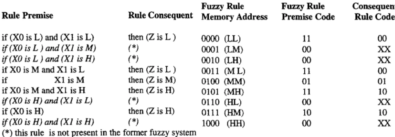
2 inputs and one output variables and 3 FSs for each variable labelled L (Low), M (Medium) and H (High). With this configuration 9, (3*), combinations of input FSs and, consequently, 9 different fuzzy rules are allowed. Suppose to have a fuzzy system made of 5 rules (a system with all the rules has 9 ones) as shown in the following table 1: in the table it has been written a possible fuzzy system where all the rules are present and the not present ones in the former are written in italics.
Once an input data set enters the implemented fuzzy system (knowing in advance the address of every predefined possible fuzzy rule), it is possible to identify the addresses of the active rules. In table 2 it is also presented, for each fuzzy rule, which memory location is addressed and the related rule code. The column titled Fuzzy Rule Premise Code (FRPC) reports the codes that enable, or do not, the input variables while the column titled Consequent Rule Code (CRC) reports the codes from 00 to 11 that selects the right output
I 3 among the possible ones. If a fuzzy rule involves both input variables, like in the first row of table 1, the I W C stores 11; if only one variable is present, like in the 5th ant 8th rule, the FRPC stores 01 and 10 respectively, and if none of the input variables is present then the FRPC stores 00.
We also want to emphasize that the rule memory word, with this solution, is quite small since it is not required to store the premise FS code as it is used in the rule address. In this example it should be noted that
where a fuzzy rule lacks, see the rules written in italics in table 1, a particular code is to be stored into the related fuzzy rule address. For these rules the
FRPC
has to be put to 00 so that, if activated by the input data set, they have to give a null contribution. Besides that, (starting from the top of table 1) in the fifth row of table 1, the fuzzy rule just requires the FS related only to the second variable X1. This means that the contribution of this rule has absolutely not to depend on the first variable XO, no matter what is its value. To get this goal, all the fuzzy rules that concern with ‘X1 is M’ as premise part, are to be written according to the following constraints: for each input XO variable value that enters the system, only one of thefuzzy rules that have ‘XO is M’ as premise part has to give a contribution to the final result; all the other ones have to give a null contribution. The same applies to the rule in the eighth row. According to the table 1, this feature is obtained by putting alternately to 00 and either to 01 or 10 depending on the fuzzy rule. In the above example (see figure 1 and table 2) there are four active rules: the ones in the fifth and sixth rows give anon null contribution while the ones in the second and the third rows give a null contribution because of the ‘00’ code of the relatedFRPC. In this example there are only 3 FSs but the above mentioned constraints can be extended to larger FS numbers. For example in case of having 7 FSs, for each FS related to the variable XO there are 7 possible FSs related to the variable X1. Anyway only the odd (even) of the rules related to the 7 FSs would have 00
as
FRPC
while the even (odd) ones would have either 01 or 10 depending on which of the present input variables is lacking. In this way becomes obvious that with a FS overlap of 2 it is impossible for more than one of the 8 fuzzy rules related to 8 FSs to be active.Rule Premise Rule Consequent Memory Address Fuzzy Rule Fuzzy Rule Premise Code Consequent Rule Code
oooo
(LL) i f ( X 0 is L } and ( X I is M ) oO01 (LM) 0010 (LH) 0011 (ML) if X1 is M then (Z is M) 0100 (MM) 0101 (MH)if(X0 is H) and (XI is L) *) 0110 (HL) if (XO is H) then (Z is H) 0111 (HM) i f ( X 0 is H} and ( X I is H) ( *) CHH) if (XO is L) and (X1 is L) i f ( X 0 is L ) ana‘ ( X l is H} if XO is M and X1 is L if XO is M and X1 is H then (Z is L ) ( *) ( *) then (Z is L ) then (Z is H)
(*) this rule is not present in the former fuzzy system
11 00 00 11 01 11 00 10 00 00
xx
xx
00 01 10xx
10xx
TABLE 1: set of fuzzy rules TABLE 2: rule addresses and codes
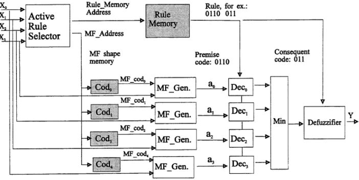
For High Energy Physics Experiments (HEPE) trigger application [ 5 ] , [6], 171, [8] we need a fuzzy system involving four 7-bit input, one 7-bit output variables and up to 7 FSs for each input variables and 8 FSs for the output variable. The degree of truth of each inpudoutput variable is described by 4 bits. At the moment only the minimum t-normdisjunction fuzzy operator is allowed. According to what previously explained, the rule memory is composed of 74=2401 seven-bit words. In fact we have a4-bit FRPC for enabling or disabling the four input variables and a 3- bit CRC for selecting one of the 8 output FSs. The fuzzy rules are sorted as earlier described from the first memory location that stores the fuzzy rule involving the four lower FSs, to the last (2401st) memory location that stores the fuzzy rule involving the four higher FSs. In figure 1 is reported adata-flow representation of the global implemented system in which only the data-flows are shown (the shaded blocks include
RAM
memories both for the rules and t h e m shapes). Once an input data set enters the system, a first block named Active Rule Selector identifies the involved FSs, see figure 1. This block isdivided (not shown in the figure) into 4 smaller blocks, one for each input variable and in each block are stored the starting and the ending points of the MFs related to each variable. To find the active rules each input value is compared with the former MF starting and ending points. Thus, once all the interval comparisons have been done, the system is able to generate the active rule memory addresses, named Rule-Memory-Address , and also to identify the shapes of the MFs related to each active rules that are stored in the MF shape memories:
MF-Address. In this way we are able to select only the few active fuzzy rules instead of processing the whole fuzzy set of rules. Consequently, the global processing time is significantly reduced. On the other hand, while a part of the architecture generates the addresses, another part generates the input variable degrees of
membership by dedicated circuits named Cod,, MI?-Gen and Dec, in another pipeline stage like in the former fuzzy chip. Then the minimum degree of membership (t-norm) is extracted among them by considering the
RRPC. If one or more input variables are not required for a given fuzzy rule, their corresponding degrees of membership, generated by the MF-Gen circuits, are to be set to the highest level (in our case the grade of tnuth
a
= 1 1 1 1) by the Dec, circuits for not giving any contribution during the minimum operation. Then, for each processed rule, two parallel adders carry out the addition between the two new contributions (numerator and denominator) to the previous ones following the Yager formula [9], [ 101 (W, is the rule weight):4
c
z,e,w,
c
eiwi
zo
= Y Defuzzifier 4 When all the active rules have been processed a division between the two final sums is computed by a fast divider. Both the adders and the divider are included into the Defuzzifier circuit reported in figure 1. It should be noted that the division process can be performed while anew input data set enters the system. In other words the inference of all the active fuzzy rules is done by means of pipeline circuits while the final division to get the output result is done in parallel with the inference process of a new input data set. Due to this solution the input data set rate is just given by the pipeline inference process that, apart from the start-up time, takes at most 16 pipeline 50 MHz phases when 16 active fuzzy rules are processed.MF shape
memory Premise code: 0110
Consequent code: 011 Dec, 4
a,
F3-
r61-
Figure
1.Fuzzy
Chip Architecturer
2. The MF generator
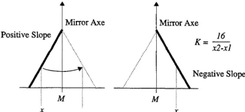
In Figure 2 is reported a symmetric triangular MF that shows the generic shape of an input MF implemented into our Fuzzy System. As regards the methodologies generally used to generate the input variable degrees of membership (degree of truth) by means of fuzzyfication process, several solutions are commonly adopted from the wide arealook-up tables to slow combinatorial circuits. For this point we have designed afast two-pipeline stage digital solution that perfectly fit our need. So it is been decided to generate the right degree
of membership starting from two MF identification parameters. In other words, once the input data set enters
the Fuzzy Processor, the involved MFs are evaluated and, according to their shapes and to the input variable values, the degree of membership are generated. As far as the involved MFs are concerned, we take into account the only MFs that, according to the input data set, produce degrees of membership different from zero; otherwise
it does not make sense to carry out the degree generation. So, in order to be able to generate the right degree of membership a small memory has been dedicated for storing, for each MF, its identification parameters. In more detail, these parameters are the middle point
M
and the slope factor K. Since it has been decided to deal just with triangular MF shapes, in order to generate the right degree of membership a straight line evaluation is to be made. It could be possible to implement the general straight line formula that is some like formula 1:Degree = [(y2 - yl)/(x2-xl)]*x
+
qwhere obviously (y2, x2) and (y1,xl) are two couples of points to identify the slope, x is the independent variable, Degree the output dependent one while q is the vertical offset. Anyway, since hardware implementa- tions of fast dividers is a problem, a different solution has been adopted. Let us suppose that the straight line formula is some like formula 2:
Degree = K*(x-M) (2)
This solution easily avoid computing any division but just multiplication and substruction processes. In detail, the formula 2 has been divided into the right hand side (substraction) and left hand side (multiplication) for timing purposes. In fact, these two processes may be pipeline so that can work in parallel on different data increasing the global throughput. The substraction job, besides shifting the straight line for forcing the MF vertex on the origin, differentiate the two cases of positive and negative slopes. If the result of the substraction is positive, that is the input variable lies on the right hand side of the MJ?, the slope is to be considered negative and vice-versa. Moreover, it has to be taken into account that in both cases of positive and negative slopes, the result of the substraction operation has to be considered with its absolute value. In other words it acts as if the left hand side of the MF would be mirrored on its right around the vertical axe to perfectly overlap its right hand side. Then both straight lines can be considered as they would be the same line. In this way the result of the substraction operation may be alwaysused. The only main difference of carrying out the Degree of membership for the two sides of the triangular MF applies after the multiplication process that, as previously mentioned, relies on the second pipeline stage. As regards this stage, it is to be considered that the K parameter includes tbe division operation presented in formula 1. In fact, let us say that for a given purpose, y2-y l may be strictly fixed to 16 (no problem if any other number is needed). This immediately means that the Degree of membership can not exceed this value or, in other words, ranges from 0 to 16. So, it is clear that the K parameter is given by the off-line division of 16/(x2-x 1). In addition, to avoid having floating point results when x2-x1 is smaller than 16, this result may be considered multiplied by the necessary power of 2 so that it may range from 0 to its maximum value by means of integer parameter. In this stage, a Wallace [ 1 11 integer multiplication method for fast digital circuits is applied. Then, since the K parameter had been multiplied by a power of 2, also the Degree is automatically multiplied by the same factor and, of course, before going to the output it is to be divided by the same factor again. Nevertheless, because of the power of 2, the division is not at all a problem and is not time consuming. In fact, dividing adigital number by apower of 2 just consists of neglecting the less significant bits while dividing by a general number implies a high increasing of hardware complexity.
4 4 ' O S i t i v e ~ ~
,,\A
K = x2-XI1
6
i
Negative Slope . . . . . . . . . . . . . . . . . . . . . . . . M M X XConclusions
Therearemanyways to designtheVLSIarchitectureofa fuzzychip [12-161, for HEPEweneedto design a fuzzy processor able to take a decision in less than 1 ps; to obtain this goal we have chosen a pipeline architecture. One ofthe problems is thedesign ofthe fuzzificationprocess, our solutionallows the two following advantages:
-
the hardware silicon area of the chip is greatly diminished since each input MF is reduced to a pair of valuesso that just by storing the Kand theMvalues any membership degree can be obtained by applying the simple formula 2;
-
the total execution time does not increase because of the computation related to the formula 2 as it is executed in two pipeline stages.References
1. Alessandro Gabrielli, Enzo Gandolfi, Massimo Masetti High Speed VLSIFuzzy Processors Designed for HEPE , SPIE - AEREOSENSE Applications and Science of Artificial Neural Networks in HEPE Invited paper Orlando 8-12 April 1996.
2. M. Masetti, E. Gandolfi, I. D'antone,A. Gabrielli, M. Cacchi, M. Russo Design and Realisation of a 50 MFIPS Fuzzy Processor in 2.0 ,um CMOS K?,SI Technology Proceedings
o f
JCIS '94 (Joint Conference on Information Sciences) pp 433-438 and the book Advances in Fuzzy Theory and Technology Vol III 2995Edited by P. Wang Duke University pp 327-340
3 M. Masetti, E Gandolfi, A. Gabrielli, F. Boschetti Digital Membership Function Generators and No- Contribute Rule Eliminator for High Speed Fuzzy Architecture WCNN '95 (World Congress on Neural Network) 16 - 19 July 1995 Washington
4 Massimo Masetti, Enzo Gandolfi, Francesco Boschetti, Alessandro Gabrielli Design of
a
1.0 mm Recon$gurable KLSI CMOS Fuzzy Processor which Runs at 100-50 MFIPS with an Active Rule SelectorProceedings of the 1955 IEEE International Conference on Systems, Man and Cybernetics October 22
-
25 1996 Vancouver Canada5 P. Ribarics
-
A Second Level Neural Network Trigger in the HI Experiment at HEM - 1992 IEEE Nuclear Science Symposium and Medical Imaging Conference6 C. S. Lindsey, B. Demby, H. Haggerty Drift Chamber Tracking withNeura1 Network - 1992 IEEE Nuclear Science Symp. and Medical Imaging Conf:
7 I. D'Antone, E. Gandolfi, M. Masetti, C. Vitullo A Fuzzy System to Detect and Count Parallel Noised Trach
ACM Symposium on Applied Computing Track on Fuzzy Logic in Application. Phoenix, March 6 - 8 1994, pag. 166-1 698 P. Ribarics - A SecondLevel Neural Network Trigger in the HI Experiment at H E M - 1992 IEEE Nuclear Science Symposium and Medical Imaging Conference
8 C. S. Lindsey, B. Demby, H. Haggerty Drift Chamber Tracking withNeura1 Network - 1992 IEEE Nuclear
Science Symp. and Medical Imaging
Con$
'9. R. Yager - A n Alternative Approach fo r the Calculation of Fuzzy Logic Control Values Published on Jap. Society Fuzzy Technology 1993
10 M. Figueiredo F. Gomides A. Rocha R. Yager "Comparison of Yager's Level Set Method for Fuzzy Logic Control with Mamdani and Larsens Methods" Letter to IEEE Transactions on Fuzzy System Vol 1, N. 2 May 1993.
11 C. S . Wallace, "A Suggestion f o r a Fast Multiplier", IEEE Trans.Electronic Computers, Vol. EC-13, Feb. 1964, pp 14-17.
12 Ikeda, Kisu, Hiramoto, Nakamura A Fuzzy Inference Coprocessor Using a Flexible Active-Rule-Driven Architecture - IKE IEEE 1992 pp 537-544
13 Pagni, Poluzzi, Lo Presti, Rizzotto Automatic Syntesis Analysis Implementation of a Fuzzy Controller
-
IEEE International Conference on Fuzzy Systems 1993 San Francisco (pag. 105-1 10)
l 4 Neichfeld, Klhche, Menke, Nolles, Kunemund A General Pulpose Fuzzy Inference Process IEEE International Conference on Microelectronics for Neural Networks and Fuzzy Systems Turin 1994 115 Ungering, Bauer, Goser Architecture of a Fuzzy processor based on a 8-bit microprocessor - IEEE
International Conference on Fuzzy Systems 1994 Orlando wag. 297-301)
11 6 Ansgar, Ungering, Goser Architecture of a 64-bit Fuzzy Inference Process - IEEE Int. Cod. on Fuzzy Systems 1994 Orlando pp 1776-1780