3d Modeling and Detailing of Silumin Piston With Static Analysis
1Kammila V Prudhvi Raj Kiran, 2Sanmala Rajasekhar,3A.V.Sridhar,4J.Harinarayana Rao 1M. Tech. Student, 2Associate.Professor, 3Associate.Professor
Dept of ME, KITS, Divili. 4
Reserch Scholar
Abstract: - Piston is the part of engine which converts heat and pressure energy liberated by fuel combustion into mechanical works. Engine piston is the most complex component among the automotives. Weight reduction has been gaining importance in automobile field because reducing in weight decreases load on the engine and thus increasing efficiency of the engine. As we all Know that Piston is made of Aluminum Alloy Such that its weight is less. The automobile industry has shown increased interest in replacing the Piston with the material having high strength to weight ratio.
Therefore the objective of this project is to present a general study on the performance comparison of composite Piston and Aluminum Alloy Piston. Dimensions and specifications used in modeling are collected from the actual Piston of Hero-Honda Splendor Bike. The Piston is modeling in solid Works.
1. INTRODUCTION
A piston is a cylindrical piece of metal that moves up and down inside the cylinder which exerts a force on a fluid inside the cylinder.
Pistons have rings which serve to keep the oil out of the combustion chamber and the fuel and air out of the oil. Most pistons fitted in a cylinder have piston rings. Usually there are two spring compression rings that act as a seal between the piston and the cylinder wall and one or more oil controls below the compression rings.
The head of the piston can be flat, bulged or otherwise shaped.
Pistons can be forged or cast.
The shape of the piston is normally rounded but can be different.
A special type of cast piston is the hypereutectic piston.
The piston is an important component of a piston engine and of hydraulic pneumatic systems .
Piston heads form one wall of an expansion chamber inside the cylinder.
The opposite wall, called the cylinder head, contains inlet and exhaust valves for gases.
As the piston moves inside the cylinder, it transforms the energy from the expansion of a burning gas usually a mixture of petrol or diesel and air into mechanical power in the form of a reciprocating linear motion.
From there the power is conveyed through a connecting rod to a crankshaft, which transforms it into a rotary motion, which usually drives a gearbox through a clutch.
1.1 CLASSIFICATION OF PISTON
Trunk pistons:
Trunk pistons are long, relative to their diameter. They act as both piston and also as a cylindrical crosshead. As the connecting rod is angled for part of its rotation, there is also a side force that reacts along the side of the piston against the cylinder wall. A longer piston helps to support this.
Trunk pistons have been a common design of piston since the early days of the reciprocating internal combustion engine. A characteristic of most trunk pistons, particularly for diesel engines, is that they have a groove for an oil ring below the gudgeon pin, not just the rings between the gudgeon pin and crown.
FIG 1.1: TRUNK PISTON
Crosshead pistons
Large slow-speed Diesel engines may require additional support for the side forces on the piston. These engines typically use crosshead pistons. The main piston has a large piston rod extending downwards from the piston to what is effectively a second smaller-diameter piston. The main piston is responsible for gas sealing and carries the piston rings. The smaller piston is purely a mechanical guide. It runs within a small cylinder as a trunk guide and also carries the gudgeon pin.Because of the additional weight of these pistons, they are not used for high-speed engines.
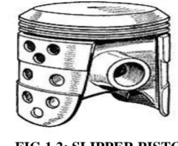
Slipper pistons
A slipper piston is a piston for a petrol engine that has been reduced in size and weight as much as possible. In the extreme case, they are reduced to the piston crown, support for the piston rings, and just enough of the piston skirt remaining to leave two lands so as to stop the piston rocking in the bore. The sides of the piston skirt around the gudgeon pin are reduced away from the cylinder wall. The purpose is mostly to reduce the reciprocating mass, thus making it easier to balance the engine and so permit high speeds. A secondary benefit may be some reduction in friction with the cylinder wall, however as most of this is due to the parts of the piston that are left behind, the benefit is minor.
FIG 1.2: SLIPPER PISTON Deflector pistons:
Deflector pistons are used in two stroke engines with crankcase compression, where the gas
flow within the cylinder must be carefully directed in order to provide efficient scavenging. With cross scavenging, the transfer (inlet to the cylinder) and exhaust ports are on directly facing sides of the cylinder wall. To prevent the incoming mixture passing straight across from one port to the other, the piston has a raised rib on its crown. This is intended to deflect the incoming mixture upwards, around the combustion chamber. Much effort, and many different designs of piston crown, went into developing improved scavenging. The crowns developed from a simple rib to a large asymmetric bulge, usually with a steep face on the inlet side and a gentle curve on the exhaust.
Despite this, cross scavenging was never as effective as hoped. Most engines today use Schnuerleporting instead. This places a pair of transfer ports in the sides of the cylinder and encourages gas flow to rotate around a vertical axis, rather than a horizontal axis.
FIG 1.3: DEFLECTOR PISTON 2. MATERIAL SELECTION FOR PISTON
2.1 Materials Used For Piston
Cast iron (used in very old engines)
Cast aluminum (most common)
Hypereutectic alloys (high silicon content aluminum-Silumin)
Carbon Graphite (being tested)
2.2 Aluminium Alloy:
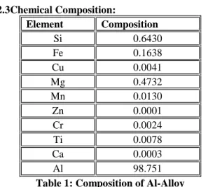
2.3Chemical Composition: Element Composition Si 0.6430 Fe 0.1638 Cu 0.0041 Mg 0.4732 Mn 0.0130 Zn 0.0001 Cr 0.0024 Ti 0.0078 Ca 0.0003 Al 98.751
Table 1: Composition of Al-Alloy
2.3 Causes of Piston Failures
• The piston is one of the most stressed components of an entire vehicle.
• As an important part in an engine piston endures the cyclic gas pressure and inertia forces at work and this working condition may cause the fatigue damage of the piston. • The investigations indicate that greatest
stress appears on the upper end of the piston and stress concentration is one of the mainly reason for fatigue failure
• Pressures at the combustion chamber may reach about 180–200 bar Speeds reach about 25 m/s and temperatures at the piston crown may reach about 400 °C
• As one of the major moving parts in the power-transmitting assembly, the piston must be designed so that it can withstand the extreme heat and pressure of combustion. • Pistons must also be light enough to keep
inertial loads on related parts to a minimum. • It also transmits heat to the cooling oil and
some of the heat through the piston rings to the cylinder wall.
• Notwithstanding this technological evolution there are still a significant number of damaged pistons. Damages may have different origins: mechanical stresses, thermal stresses, wear mechanisms, temperature degradation, oxidation mechanisms and etc.
• Fatigue is a source of piston damages. • Although, traditionally, piston damages are
attributed to wear and lubrication sources, fatigue is responsible for a significant number of piston damages.
• And some damages where the main cause is attributed to wear and/or lubrication
mechanisms may have in the root cause origin a fatigue crack.
• Fatigue exists when cyclic
stresses/deformations occur in an area on a component.
• The cyclic stresses/deformations have mainly two origins: load and temperature. • Traditional mechanical fatigue may be the
main damaging mechanism in different parts of a piston depending on different factors. High temperature fatigue (which includes creep) is also present in some damaged pistons.
• Thermal fatigue and thermal–mechanical fatigue are also present in other damaged pistons.
Mechanical fatigue damages at piston head and piston pin holes is the reason of several damaged engine pistons. Static stresses concentrate mainly at pin holes both for petrol and diesel pistons, as well as for automotive, train, and other engine fields. This explains cracks initiated at piston pin holes.
3. FINITE ELEMENT ANALYSIS
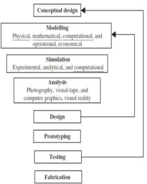
The Finite Element Method (FEM) has developed into a key, indispensable technology in the modeling and simulation of advanced engineering systems in various fields like housing, transportation, communications, and so on. In building such advanced engineering systems, engineers and designers go through a sophisticated process of modeling, simulation, visualization, analysis, designing, prototyping, testing, and lastly, fabrication. Note that much work is involved before the fabrication of the final product or system.
Figure 3.1: The design Process
The very basic concept of FEM is a system-a-body of a structure can be divided elements of finite dimensions, called “finite elements”. The fundamental concept of the finite element method is that any continuous quantity, such as temperature, pressure or displacements can be approximated by a discrete model composed of set of piece wise continuous functions defined over a finite number of sub domains. These series of functions are piecewise continuous and should approach the exact solution as the number of sub domains approaches infinity. FEM is more appealing to the engineer as it can be explained through the physical concept and also for heat transfer and fluid mechanics. It is amenable for programming on a digital computer in a systematic way. The scope of application is practically very much large covering wide range of analysis problems. 4. DESIGN MODEL OF PISTON
Design of Piston:
The Piston is Designed Based on the following dimensions of Hero-Honda bike Piston. Design of piston is carried out in the Solid works.
Dimensions of the piston:
Parameter Actual
Values
Piston length 37 mm
Piston diameter 49.5mm
Pin hole external
diameter 12.7 mm
Pin hole internal
diameter 6.6 mm
Piston ring axial
thickness 0.8mm
Radial thickness of
ring 2mm
Depth of ring groove 2.01mm
Gap between the
Rings 2.6mm
Top land thickness 5.6mm
Thickness of piston at
Top 6.65mm
Thickness of piston at
open end 1.64mm
Table4.1: Dimensions of The Piston
4.1 SOLID WORKS
Solid Works is a 3D mechanical CAD (computer-aided design) program that runs on Microsoft Windows and is being developed by Dassault Systems Solid Works Corp. Solid Works is currently used by over 2 million engineers and designers at more than 165,000 companies worldwide. FY2011 revenue for Solid Works was 483 million dollars.
FIG 4.1: DESIGN OF THE PISTON 4.1.1 Meshed model of Piston
only quad and triangular elements are used. Figure shows the meshed model of a piston.
FIG 4.2 MESHED MODEL OF PISTON
4.2 STUDY RESULTS
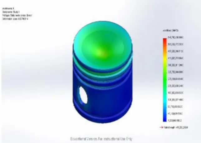
4.2.1 STRESS Analysis:
Figure shows the equivalent Von-Mises stress induced in Al-Alloy Piston and Silumin under the action of 3.15*106N/m2load. The maximum stress is induced in Al-Alloy is 5.4*1011N/m2and maximum stress is induced in Silumin Alloy is 2.76 *1011N/m2 Red zone indicates the area of maximum stress and blue zone indicates the area of minimum stress.
FIG 4.3: VON MISES STRESS FOR THE AL-ALLOY PISTON
FIG4.4: VON MISES STRESS FOR SILUMIN PISTON
FIG 4.5: DISPLACEMENT FOR AL-ALLOY PISTON
FIG 4.7: STRAIN FOR AL-ALLOY PISTON
FIG 4.8:STRAIN FOR SILUMIN PISTON RESULTS Comparisons: Mater ial Used Weigh t (N) Max Stress (N/m^2 ) Max Displaceme nt (mm) Max Strain Al 2024-T6 0.3660 86 5.4874 e+011 668.2 4.371 36 SILU MIN 0.3476 51 2.7464 e+011 314.777 2.062 89 Table:Comparisons Between the Materials
CONCLUSION
In this project, a piston is modeled in 3D modeling software SOLIDWORKS. Present used material for piston is Cast Aluminum. The Cast aluminum is replaced with SILUMIN. The weight of the piston is less since its density is less.
Static analysis is done on the piston by applying the pressure to verify the strength of the piston using 2 materials. The Max Strain,
Displacement, and Max Stress for the SILUMIN-Alloy piston are less than that of Al-SILUMIN-Alloy Piston. so in future SILUMIN Alloy can be adopted in the commercial automobiles to enhance the performance range of the engine from piston’s side. The analysis is carried out in the commercially available software Solid Works.
REFERENCES
[1] Design and Analysis of Piston Design for 4 Stroke Hero Bike Engine by VinodYadavApplied
Mechanics, MANIT Bhopal. Email:
[email protected] &Dr. N. D. Mittal Professor, Applied Mechanics,MANIT Bhopal -International Journal of Engineering Innovation & Research Volume 2, Issue 2, ISSN: 2277–5668.
[2] Thermal Cyclic Fatigue Analysis of Three
Aluminum Piston Alloys by
WilfriedWunderlich&Morihito Hayashi of Tokai University, Faculty of Engineering, Department of Material Science, 259-1292 Hiratsuka, Kanagawa, Japan-International Journal of Material and Mechanical Engineering, 2012, 1: 57-60.
[3] Piston Strength Analysis Using FEM by Swati S Chougule (Second Year M.E. CAD/CAM & Robotics, Department of Mechanical Engineering, PIIT, New Panvel, Mumbai University, Navi Mumbai,) &,Vinayak H Khatawate(Asst. Prof. Department of Mechanical Engineering, PIIT, New Panvel, Mumbai University, Navi Mumbai)-International Journal of Engineering Research and Applications (IJERA) ISSN: 2248-9622 www.ijera.com Vol. 3, Issue 2, March -April 2013, pp.1724-1731 1724.
[4] Parametric And Material Optimization Of Two Wheeler Piston Using Aluminum Alloy 7475-761
And Aluminum Alloy 6061 by
Soniakaushik,Rayapuri Ashok,Mohammed zubairnizami-Department of Mechanical Engineering Lords Institute of Engineering & Technology [email protected] of Advanced Trends in Computer Science and Engineering.
[6] Fatigue on engine pistons – A compendium of case studies by F.S.SilvaDepartment of Mechanical Engineering, University of Minho, Azure´m,
4800-058 Guimara˜ es,
Portugal-WWW.Sciencedirect.Com.
[7] Aluminum Silicon Carbide (Al-Sic) for Advanced Microelectronic Packages by Mark Occhionero, Richard Adams, Kevin Fennessy, and Robert A. HayCeramics Process Systems, Corp.Chartley, MA 02712.