87
ASPECTS ON THEORETICAL ANALYSIS OF WORKING PROCESS
PERFORMED BY TECHNICAL EQUIPMENTS FOR CHOPPING PLANT
DEBRIS IN ORDER TO CLEAR THE FIELD
DALADIMOS P., BORUZ S., BADESCU M., ALEXIOU A.
Keywords: chopping, rotor, vegetal debris
ABSTRACT
The paper presents theoretical aspects on working process of rotors of technical equipments designed for chopping vegetal debris and fodders. Generally, the chopping devices with rotor, with the rotor axle in horizontal plane and normal position (perpendicular) with the machinery moving direction are used for constructing equipments for harvesting fodder crops or for those of chopping vegetal debris where they perform multiple tasks. They make the cutting, the chopping of plants and throwing the chopped material into the collecting trail or, with the case of cutting and chopping machinery, the evenly spreading of chopped material over the soil surface. The main factors that influence the chopping degree are the physical – mechanical features of the chopping material that are very different with the crop variety and the constructive and functional parameters of the chopping device.
INTRODUCTION
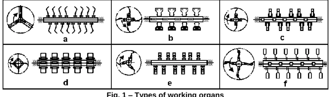
In principle, a cutting – chopping device from a technical equipment designed for collecting and chopping vegetal debris or fodder crops is formed of the axle or driving drum, the working organs (knives) and the frame. The working organs are jointly mounted on the axle or the drum (figure 1) by mean of bolts or axles. The working organs can be, usually, knives or jointed bars with inertial mass (hammers) and are located along the drum on 2-4 rows placed after an propeller with a single head. Between two neighbor elements there is an area of covering of 7-25 mm. The chopping devices with joint knives have the diameter at the margin of knives of D = 450 - 710 mm, speed n = 1600 - 2300 rot./min, the working width (the length of the drum) L = 1400-2100 mm. The power needed for drum driving is P=18-33kW. The working organs can be made of a single piece or from many pieces (support, knife, joint arm, ear).
Fig. 1 – Types of working organs
88
designed, especially, for harvesting herbaceous fodder crops yet they can be used for harvesting crops with thick stems, for instance corn stems that remain after corn cobs harvesting. The chopping devices are simple, robust yet they lose much material and do not perform a satisfactory uniformity of the length of chopped parts.
MATERIAL AND METHOD
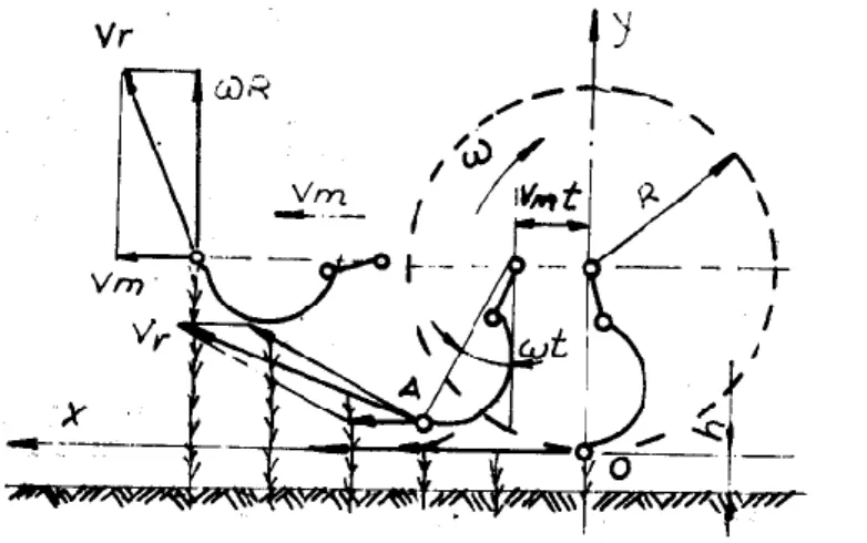
The machinery for cutting and chopping vegetal debris in order to clear the field have the axle of the rotor placed horizontally and in normal position (perpendicular) on the machinery moving direction.
Fig. 2 – The kinematics of the cutting and chopping device
In these conditions, the movement equations of a point from the knife, located at radius r[0, R], R that is the radius of the extreme point of the knife are:
sin
(1 cos ) m
x v t r t
y r t
,
and the speed components are: cos ,
sin
x m
y
v v R t
v R t
The absolute speed of the knife (the speed of plant cutting or the resulted speed) is given by the relation:
2 2 2 2 2 2
2
cos
1
2 cos
r x y m m m
v
v
v
v
r
v
r
t
v
t
(1) Where λ is the kinematic regime of device and it has the formula:p
m m
v
r
v
v
(2)In order to ensure an inertial cutting, namely without support (or without opposite knife) there is need that the speed of knives to be superior to a limit speed that corresponds to inertial cut, which means:
lim
p
v v (3)
where vlim is the speed for inertial cut. Generally, vIim = 8 - 12m/s.
In practice, the effective speed of cutting is higher than the limit speed.
89
p
v
R
where: ω is the angular speed of a point placed on the knife edge;
R is the radius of the circle made by a point placed on the knife edge; Generally, ωR = 30 ÷ 50 m/s.
During knives action on plants stems they are declined toward machinery movement direction. After machinery passing, the stems get back to initial position and it determines the increasing of the stubble height hm compared with the default h. This increase is determined by ε coefficient that is the ratio between the effective height of the stubble, hm, and the default working height, h.
ε= hm / h (4)
In order to harvest a quantity of material as big as possible per surface unit there is necessary to achieve a height of stubble hm as low as possible. The working height h of the knives is limited by the state of soil surface (the knives are not allowed to touch the soil). There results the fact that ε should be as closed as possible to 1.
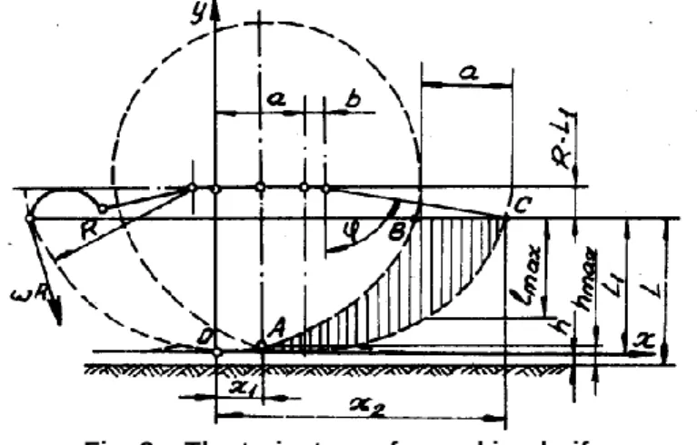
Fig. 3 – The trajectory of a working knife.
The length of the chopped material, when the plants stay vertical during cutting, varies from zero in points A and C till Imax in point B. On the drawing in figure 3 the trajectory of a knife while working is represented by an interrupted line and the working zone is shaded. If the stems are vertical during cutting, the height of the stubble varies between h and hmax. The average length of the chopped material is given by the following ratio:
2 1
,
ABC medS
l
x
x
(5)where: SABC is the surface of the working zone of a knife; x1 and x2 are the abscissas of A and C points; A – the point where the working zone begins; C – the point where the working zone ends.
The supplying of the chopping device namely the advance of machinery at a rotation of the chopping axle, is „a” and it has the following formula:
a=
vm 2
90
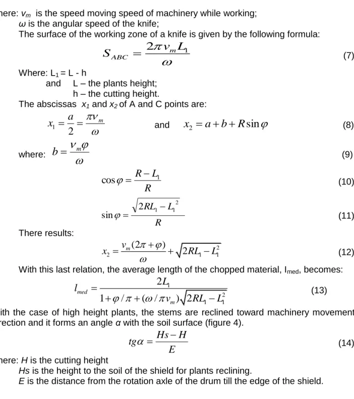
where: vm is the speed moving speed of machinery while working;
ω is the angular speed of the knife;
The surface of the working zone of a knife is given by the following formula:
1
2
m ABCv L
S
(7)Where: L1 = L - h
and L – the plants height; h – the cutting height.
The abscissas x1 and x2of A and C points are:
ma
x
2
1 and
x
2
a
b
R
sin
(8)where:
mb
(9)R
L
R
1cos
(10)R L RL1 12
2
sin
(11)There results:
2
2 1 1
(2
)
2
mv
x
RL
L
(12)With this last relation, the average length of the chopped material, Imed, becomes:
1
2 1 1
2
1
/
( /
) 2
med
m
L
l
v
RL
L
(13)With the case of high height plants, the stems are reclined toward machinery movement direction and it forms an angle α with the soil surface (figure 4).
E
H
Hs
tg
(14)where: H is the cutting height
Hs is the height to the soil of the shield for plants reclining.
E is the distance from the rotation axle of the drum till the edge of the shield.
91
The maximal length of the chopped material is:
max
sin
/
cos
m
R
v
l
(15)After first cutting, the stem is taken by the knife and placed on the opposite knife and the length of the chopping depends on the supplying of the chopping device namely of the machinery advance „a”.
The average length of the chopped fragments, Io, can be approximated by the formula:
0
2
cos
cos
m
v
a
l
(16)From the analysis of this formula there results that the chopping height increases along with the machinery working speed, Vm, and along with the increasing of plants reclining (angle α). The variation of the chopping length is characteristic for chopping devices with joint knives and this fact do not recommend them for harvesting fodder crops for silage. Generally, the uniformity of the chopped material length, with the case of herbaceous plants is of 20-45%.
RESULTS AND DISCUSSIONS
The average length of the fragments of the chopped material is given by formula (13). The main parameters of the crop that intervene in this formula (L and h) have a hidden influence contained in the L1 function. Because the explanation of this formula till the last parameter would be too complex, we prefer a numerical example.
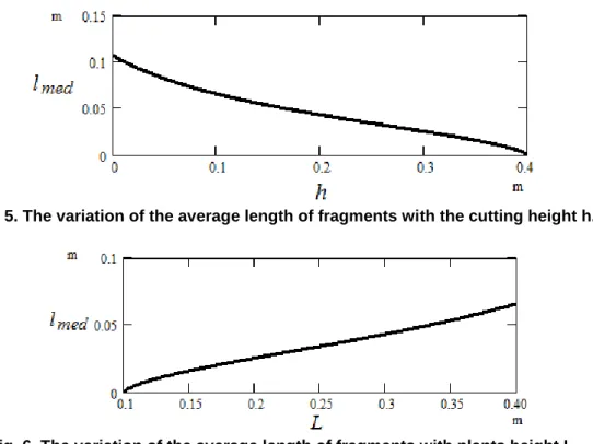
Fig. 5. The variation of the average length of fragments with the cutting height h.
92
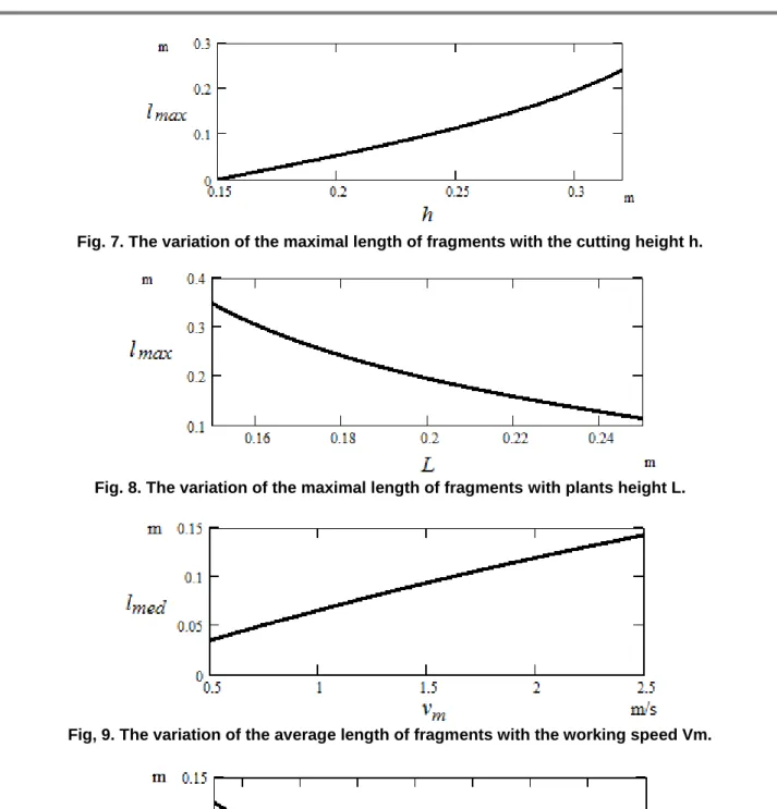
Fig. 7. The variation of the maximal length of fragments with the cutting height h.
Fig. 8. The variation of the maximal length of fragments with plants height L.
Fig, 9. The variation of the average length of fragments with the working speed Vm.
Fig. 10. The variation of the average length of fragments with the angular speed of knives ω. From figures 5 and 6 there results that the average length of vegetal fragments increases with L and decreases with h. The maximal length of the fragments decreases with L and increases with h (figures 7 and 8). The average length of fragments increases with the working speed, as seen in figure 8 and decreases with the angular speed of the cutting device, as shown in figure 10.
93
m, h=0.1 m, R=0.25 m, vm=1 m/s, n= 1,000 rot/min (104 rad/s), Hs= 0.3 m, H=h, E= 0.35
m.
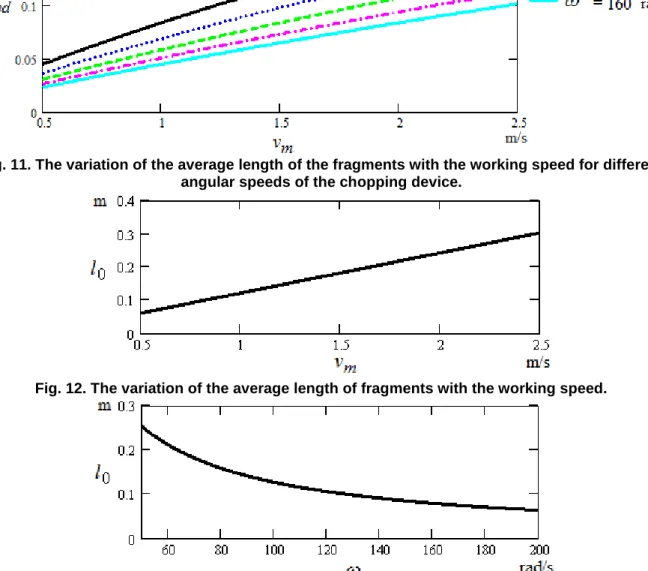
Another graph, more complete than the upward ones, for the variation of the average length of the vegetal fragments (there can be made for other functions, too) is given in the figure 11. There is represented the average length of the fragments with the working speed, for different values of angular speed of the cutting device, included in usual interval for working devices.
The variation of the average length of chopped fragments, Io, is given by (16) with the working speed, with the angular speed of the chopping device and with the plants reclining angle given in figures 12, 13, 14; they confirm the text explanations.
Fig. 11. The variation of the average length of the fragments with the working speed for different angular speeds of the chopping device.
Fig. 12. The variation of the average length of fragments with the working speed.
94
Fig. 14. The variation of the average length of fragments with plants reclining.
CONCLUSIONS
The theoretical study n the working process of a rotor for chopping vegetal mass demonstrates that the main factors that influence the chopping degree are:
- Physical and mechanical properties of the chopping material that highly differ in function of crop variety;
- The constructive and functional parameters of the chopping material as: the knife and opposite knife type as geometrical shape, the movement speed of the machinery, the speed and the angular speed of the rotor, the pattern of placement of knives on the rotor, the number of knives on the rotor, the inertia momentum of the rotor, the balancing at the impact between knife and the vegetal mass, the stability of knives movement;
- The wearing degree of the knives and opposite knives that modify the distance between knife and opposite knife and the dynamics of rotor movement by modifying the inertia momentum and, consequently, by vibrations in rotor bearings;
In order to ensure an inertia cutting, namely, without support (or without opposite knife) there is necessary the knives speed to be higher than the limit speed needed for inertia cutting.
The length of the chopped fragments increases with the increasing of the working speed of machinery, Vm, and with the plants reclining angle (α). For the chopping devices with joint knives the high variation of the chopping length is characteristic. Generally, the uniformity of the length of the chopped material is of 20-40%.
Because during cutting the chopped material falls on a curve shape, the inferior part of the remained vegetal mass (stubble) presents some height increases, h. Their height depends on parameters s and λ. By increasing λ, the height of the crests diminishes resulting a uniformisation of the stubble. With high values of λ the fuel consumption increases because of chopping the same quantity of vegetal mass many times.
The increasing of the λ ratio implies the increasing of the peripheral speed of the knife, with influence on rotor balancing as well as increasing the length of the chopped material or of chopping degree.
BIBLIOGRAPHY
1. Cristea M, Boboşilă M. şi colab. - Studiul procesului complex de tăiere, transport şi distribuire pe sol a masei vegetale realizat de o maşină de cosit şi mulcit în livezi. -Buletinul Conferinţei de Dinamica Maşinilor CDM-Braşov-1994
2. Daladimos Paraskevas, Badescu M., - Experimental research regarding working qualitative indices of plant debris chipper TR-2.5, 5th International Mechanical Engineering Forum Prague 2012, 20- 22 February 2012, Prague, Czech Republic 3. Dash R.C. , Sirohi N.P.S. , A Computer Model to Select Optimum Size of Farm Power
95
Engineering, International: the CIGR Ejournal. Manuscript PM 08 012.Vol. X. November, 2008;
4. Donaldson G. F., Farm machinery capacity. An economic assessment of farm machinery capacity in field operations. Studies. Roy. Commn Farm Mach.,
Ottawa 1970 pp. xi + 161 pp.;
5. G. Ivanetz, V. Ovsyanko, A. Vyrski, V.A. Pigenko, COMPUTER MODELING OF BEET HARVESTER DIGGING. BODIES-SOIL INTERACTION , Journal of Research and Applications in Agricultural Engineering, 2007, Vol. 52(1);
6. Meca V. A.,Cârdei P., Studies and researches for unifying the resistance expression of machines designed to soil tillage with applications in their working regime optimization, INMATEH-Agricultural Engineering, vol. 36. No. 1 / 2012;
7. Neculăiasa V., Dănilă I., - Procese de lucru şi maşini agricole de recoltat. Editura A. 92, Iaşi, 1995.
8. Plouffe C., Tessier S., Angers D. A., Chi L., Computer Simulation of Soil Compaction by Farm Equipment, Journal Natural Resources Life Science Education, vol. 23, no.1, 1994;
9. Şandru A., Popescu S., Cristea I., Neculăiasa V., Exploatarea utilajelor agricole, Editura Didactică şi Pedagogică, Bucureşti, 1983;