THE PROCESS OF SETTING THE PARAMETERS
FOR ENSURING PASSAGE OF OVERSIZED
CARGOS
JAN PETRU*, VLADISLAV KRIVDA
Dept of Transport Constructions, Faculty of Civil Engineering,
VSB–Technical University of Ostrava, Ostrava, The Czech Republic
Received 22 August 2018; accepted 23 April 2019
Abstract: Engineering and the industry very often produce above-standard products concerning their dimensions and weights. There is often a problem with the transport of these products both within Europe and in subsequent transport all around the world. Because of these reasons, several projects to remedy the situation were implemented in the Czech Republic. The article describes the results of many years of research, which observed ensuring the passage of oversized cargos on roads. Further, the measurements, which were
carried out, are presented in this paper − the measurement of an oversized
vehicle using Global Positioning System devices, creation and modelling of missing cars in programs to verify the swept path, comparison of created models with the measurement using Global Positioning System devices. Then the results of the implemented researches, the suggested parameters, and modelled cars are used for the suggestion of technical parameters of backbone network of roads. On these roads, the loads are transported. The results are also used for verification of critical points of the route, e.g. problematic places and intersections.
Keywords: Global Positioning System (GPS), intersection, oversized cargo, software, swept paths.
* Corresponding author. E-mail: [email protected] Jan PETRU (ORCID ID 0000-0003-0034-2062)
Vladislav KRIVDA (ORCID ID 0000-0003-3031-6439)
Copyright © 2019 The Author(s). Published by RTU Press
20 19/14 (3)
Introduction
The Czech Republic has a long tradition in engineering and industry. These industries often produce products whose dimensions and weight are considered above standard. For these products arises the problem of transport on chosen routes both within Europe and within all around the world. Many products are also only transported across the Czech Republic. These are various oversized products from neighbouring countries, i.e. Slovakia, Austria, Poland and Germany.
It is very complicated to transport products by rail considering the clearance gauge and radii of arcs. Water transport is also available only to a limited extent in Czech conditions. Therefore, it is necessary to carry out the transport on chosen routes of road infrastructure with the assistance of special vehicles (Petru & Krivda, 2017). The road network in the Czech Republic is dimensioned for these transports only partially. The backbone routes, which ensure the spatial requirements for the passage of transport, are missing entirely.
Similarly, the bleak situation is in many other European countries. At the same time, there exists “European Best Practice Guidelines for Abnormal Road Transports” from 17th May 2006 (European Commission
Directorate…, 2006) recommending to the member states to build a Europe-wide network of corridors for the transport of oversized cargo. By the Directive (European Commission Directorate…, 2006), Finland has, in most details, solved conditions for excessive transport. The Finnish network of roads for the transport of huge oversized cargo is predefined (Petru & Krivda, 2017). They also created sets of standard values and instructions for dimensioning infrastructure of roads in Finland (European Commission Directorate…, 2006; Laitinen, Stenman, Heikkilä, & Väätäjä, 2013; Nyrhinen & Gröndahl, 2007; Setälä, 2003). Within the research the regulations concerning designing of roads were examined, e.g. from Holland (DHV Environment and Transportation, 2005), Germany (Forschungsgesellschaft für Straßen-und…, 2005) and the USA (Transportation Research Board, …, 2000). None of these regulations set parameters, which are possible to use as a model for the creation of Czech regulation. For these reasons, several projects dealing with the remedy of the situation were done in the Czech Republic (Krivda & Petru, 2016; Petru, 2014)
the Parameters for Ensuring Passage of Oversized Cargos
technologies were performed. Then software models of vehicles were created to determine (verify) the parameters, which ensure the passage of transports on roads (in more details the issue is described in (Krivda & Petru, 2016; Petru, 2014). The result of the projects was the determination of spatial parameters (Tables 3 and 4 containing data and values of radii of corners, heights, widths, vehicles for verification of the passage), which were applied to oversized and excessive cargos on backbone routes.
2. Excessive and oversized transport
and its problematics
Oversized or excessive transport is such a transport, which exceeds the maximum permitted dimensions specified in a relevant regulation. In the Czech Republic, the values are as follows: the maximum permitted width of the vehicle is 2.55 m, the maximum permitted height of the vehicle is 4.20 m, the maximum permitted length with two trailers or one semitrailer, and one trailer is 22.00 m. The maximum permitted weight of vehicles is 48.00 t.
There are no determined backbone routes for the transport of oversized cargo in the Czech Republic; the transporter or the escort chooses the route. The choice is based on previous experience and the real conditions of the route. The selection of the route depends on the type of cargo, its dimensions and weight. The competent administrative authority grants the final approval of the proposed route (Petru & Krivda, 2017). Due to the passage on roads and bridges, the choosing of the suggested route often takes several months. The critical points on the routes of the oversized cargos are the level and interchanges of roads, bridges, toll gates, traffic signs, electric and other lines. The issue is described in more details in (Krivda & Petru, 2016; Petru, 2014).
20 19/14 (3)
3. Measurement of the vehicles with the help
of Global Positioning System technology
It was necessary to use the electronic library (database) of vehicles to determine (verify) the parameters, which ensure the passage of transports on roads. Because a library, which meets the requirements, was missing, it was necessary to have the vehicles created. For correct behaviour of the vehicles, it is necessary to know their technical parameters and to verify their behaviour on real vehicles and during the transport of the oversized cargos.
Based on these facts, a project with the title “The Swept Paths of Design Vehicle of Excessive Transport” was being solved at the Technical University Ostrava (Petru, 2012). In this project, the measurements were realised on chosen sets of vehicles, which transport oversized or excessive cargos of Czech and international transporters to cover the most critical types of transported cargos. These sets were then measured using GPS technology.
Global Positioning System devices were fitted to the vehicle (towing vehicle) and a low-loading trailer with the help of specially designed fitting devices for measurement purposes. The course of the measurement was monitored by static video cameras and photos were taken. A drone also monitored the swept paths (Petru, 2013).
3.1. Apparatus and methods of measurement
For the measurement, two sets of devices Topcon HiperGD (GPS observation) and one set Topcon HiperGGD (GPS/Global Navigation Satellite System observation) were chosen. Each set consists of a Global Navigation Satellite System (GNSS) device, data recorder for controlling and saving the measured data and a mobile phone. The mobile phone was used to create a data connection to the source of the corrections. The application TopSURV was used to record the measurement. It is a standard application for operating the device Topcon. Due to the requirements for the accuracy of the measurement, the method of phase measurement with correction in real-time Real-Time Kinematic (RTK) was chosen. The source of the corrections was a permanent reference station called VSBO. The size of the measuring base was 6.50 km.
3.2. Installation and setting of the apparatus
the Parameters for Ensuring Passage of Oversized Cargos
the cab of the towing vehicle. The second apparatus (hereinafter CONNECTION) was installed to the axis of the connection of the towing vehicle and semitrailer. The antenna of the last apparatus (hereinafter SEMITRAILER) was situated behind the last axle of the semitrailer in its axis. The location of the individual apparatus CAB and SEMITRAILER along the axis of the towing vehicle and semitrailer was precisely targeted for further evaluation.
The position of antennas was determined with the emphasis on the use of a minimum number of GNSS apparatus. This set-up made possible the assembly of the outline of the towing vehicle and semitrailer with the usage of the relations of analytical mathematics and information from the technical documentation of the set of vehicles.
The fixing of GNSS apparatus to the cab and low-loading trailer was realised with the help of neodymium magnets and a specially produced bearing structure. (Metal sheets connected by screws. There was polystyrene between them and a wooden insert for shielding of the magnet. On the upper sheet there was welded a special screw with a thread for fixing the GNSS apparatus).
3.3. Method of measurement
The individual routes (movements) of the driving set were determined for the measurement. The first movement of the set was
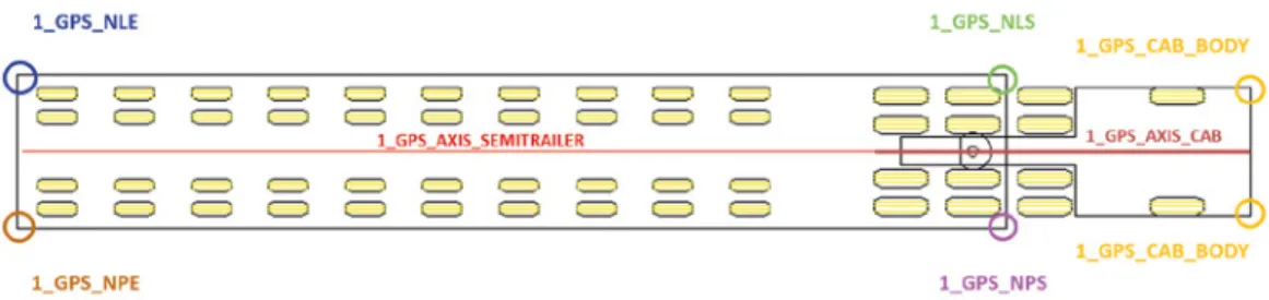
Figure 1. Placement of Global Navigation Satellite System apparatus on the set
20 19/14 (3)
directly straight and then back to the original position; it was used for the determination of the GPS. Subsequently, the movements took place on the determined circular route. The movements were measured at various speeds. The initial speed of the set was 5 km/h. During the passage, the speed of the set increased. The information about the speed of the set was possible to be determined from individual points of the GPS. The measurement was recorded on video cameras and photos were taken, including monitoring from bird perspective (drone). From the records, the movement of axles, while changing the speed and the position (turning) of the towing vehicle to the low-loading trailer were obvious.
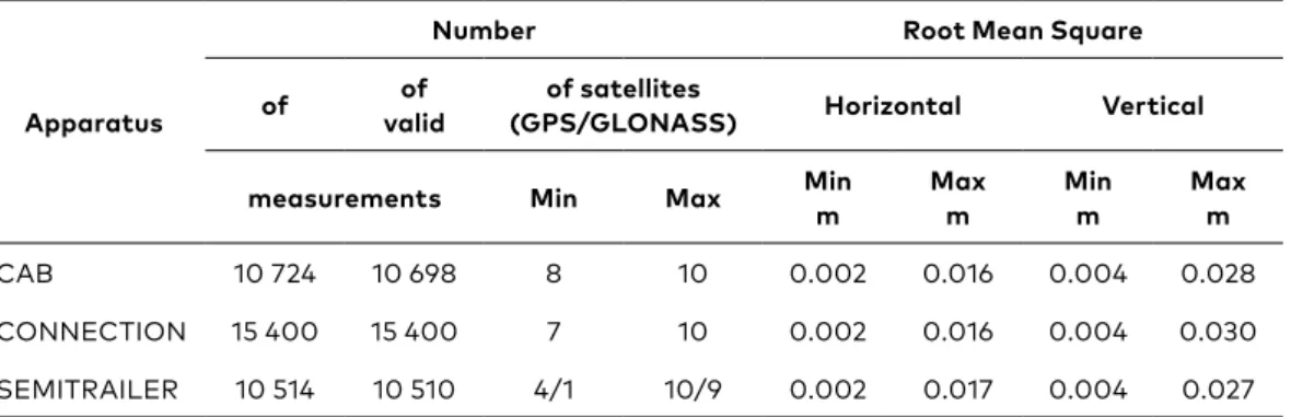
The apparatus was set to collect data with an interval of 1 s. The collection of data was set so that only the RTK measurements, which happened with the solution of ambiguity in the length of the base in the level of importance 99.5%, were accepted as valid. The measurement was done in Unified Trigonometric Cadastral Network System (S-JTSK) coordinate system (Table 1).
Table 1. Statistics of measured data
Apparatus
Number Root Mean Square
of validof (GPS/GLONASS)of satellites Horizontal Vertical
measurements Min Max Minm Maxm Minm Maxm
CAB 10 724 10 698 8 10 0.002 0.016 0.004 0.028
CONNECTION 15 400 15 400 7 10 0.002 0.016 0.004 0.030
SEMITRAILER 10 514 10 510 4/1 10/9 0.002 0.017 0.004 0.027
3.4. Processing the results of the measurements
the Parameters for Ensuring Passage of Oversized Cargos
and semitrailer). Moreover, a class of point features representing the outline of significant edges in the ground plan of the towing vehicle and the semitrailer.
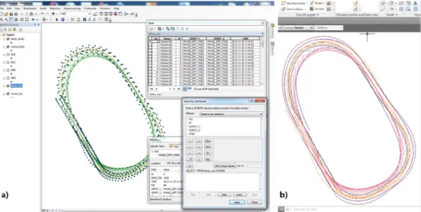
Figure 2a shows a part of processed points from GNSS apparatus based on the distinction by time and resulting measurement when the measured set performed all the movement along the specified route. Figure 2b also shows the axis of the towing vehicle and the semitrailer. The points were subsequently differentiated by the position on the vehicle in Figure 3 as follows:
• 1_GPS_NLE – these points represent the back edge of the semitrailer on the left side;
• 1_GPS_NLS – these points represent the front edge of the semitrailer on the left side;
• 1_GPS_NPE – these points represent the back edge of the semitrailer on the right side;
• 1_GPS_NPS – these points represent the front edge of the semitrailer on the right side;
• 1_GPS_CAB_BODY – these points represent the front edge of the cab on the right and left sides (back points are not used because the modelled cars from the program AutoTURN do not have the end of the back edge of the towing vehicle depicted); the following axes were used to determine the exact position;
Figure 2. Measured points
a) example of a part of processed points from Global Navigation Satellite System apparatus
20 19/14 (3)
• 1_GPS_AXIS_CAB – these are the points of the towing vehicle (cab); • 1_GPS_AXIS_SEMITRAILER – this is the axis of the semitrailer of
the measured oversized set of vehicles.
For evaluation and processing of the points in the program ArcGIS Desktop, the individual data were converted and exported to the format readable by AutoCAD CIVIL 3D. After loading into AutoCAD, the points were connected to create an outline curve of the vehicle and represents individual edges of the semitrailer and the towing vehicle. The resulting curves of the edges of the semitrailer and the towing vehicle supplemented by the image of the axes of the semitrailer and the towing vehicle are shown in Figure 2b. These curves were then used to verify the modelled vehicle in AutoTURN program.
4. Modelling the vehicles for verification
of the parameters of the passage
Based on the analysis of the observed transports and information about the parameters of individual low-loading trailers, types of vehicles and cargos, it was possible to create the design vehicles. It was used for the verification of the trajectories of the passage of oversized sets using, e.g. the software AutoTURN. Such created models of vehicles were verified by the use of GPS technology. It was fitted to the set carrying the oversized cargos (towing vehicle, low-loading trailer). The method of measurement was stated in Chapter 3.
The modelling of design sets of vehicles was divided into six categories. The categories were set based on the type of the transported cargo, the maximal weight of the cargo and the type of low-loading trailer. These categories are seen in Table 2.
As an example of the modelled car in AutoTURN program, the vehicle of oversized set described in Chapter 3 will be used.
the Parameters for Ensuring Passage of Oversized Cargos
Table 2. Division of modelled vehicles in AutoTURN program into categories
Division of vehicles into categories
M ax im um w ei gh t o f t he c ar go a nd ty pe o f lo w -lo adi ng t rai le r
40 t − (49 t) – length up to 39 m
80 t *THP axis − 370 t
*THP axis special
classic up to 29 t
telescopic up to 36 t –
length up to 30 m platform sets depth sets THP axis
− combined
connection of two sets
13.5 m semitrailer
classic
jumbo
depth sets telescopic sets
inserting the frame
fifth-wheel depth sets
telescopic sets frame semitrailer hanging between the axles platform sets Ty pe s o f t ra ns po rt ed c ar go s wheel technology cauldron bodies
bridges generators structures tanks
cylindrical containers
heavy construction
technology
reactors transformers machines structures
steel structures heavy agriculture technology containers complete bridges wooden and steel semi-finished products machines
wood silos steel structures
transformers individual structures
sheets light metal technology belt machines concrete
structures
generators long bridge parts technological units streel structure prefabricates wooden structures
turbines … … wooden
trusses construction
parts
cylindrical metal parts
parts of mills containers
aviation equipment
tanks bins trolleybuses
… parts of wind power plant
extreme cargos
…
20 19/14 (3)
4.1. Technical data and parameters of a modelled vehicle (Goldhofer STHP/LTV Y)
The example of creating the vehicle is described on the set by THP axes. THP axes are assembled into trailer and semitrailer variants from four-axle up to extreme usage of all Y-axes (number of axle axis). The load area of the width of 6 m is at the side connection determined for extremely heavy and oversized cargos. These low-loading trailers are used for transport of cargos such as bridges, reactors, containers, transformers, generators, turbines, mill shells, nuclear power components and other extreme cargos considering the weight and dimensions.
Schematic representation of the set is evident from the technical list in Figure 1. The scheme and details were obtained from the measuring of the set. Further technical details were obtained from the company Goldhofer AG. It is the producer of low-loading trailers for transport of oversized and excessive cargos. For modelling, other types of low-loading trailers companies transporting oversized and excessive cargos were contacted and the producers of low-loading trailers, e.g. companies Goldhofer AG, Nooteboom, or the distributors of these companies.
It is only possible to create a partial portfolio of sold sets in the program (it is possible to modify and combine the sets – this way dozens of options of set types from one producer can be created). Therefore, the sets were filtered to sets, which are found in Czech companies. Further, the sets transporting oversized cargos from neighbouring countries were also created.
Figure 4 shows windows in AutoTURN program, which are used for the modelled type of a vehicle (sets, which were tested with the help of GPS technologies). Technical parameters were inserted into the program from the technical specification of the manufacturer. Other parameters, which were necessary for the program AutoTURN but were missed in the technical lists, were measured.
the Parameters for Ensuring Passage of Oversized Cargos
Testing of created vehicles was done in drawings on intersections in the AutoCAD program, where the passage of sets of vehicles was observed. Based on the real behaviour of the vehicle and the measurement of the GPS technology, the individual parameters of created vehicles in AutoTURN program were adjusted.
5. Verification of the vehicle by the Global
Positioning System measurement
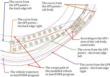
The created vehicle in AutoTURN program was then verified by the processed and evaluated measurement with the help of GPS technology. The curves created based on the measurement from the points of the GPS were compared to the swept path of edges of the low-loading trailer of the created vehicle in AutoTURN software. Figure 5a shows the curves from points of GPS and the swept path of the modelled vehicle in AutoTURN program.
In the drawing, the created vehicle in AutoTURN program was situated precisely to the starting position, where the set of vehicles transporting an oversized cargo was during the measurement with GPS technology. With the help of the program ArcMap, the average speeds of the vehicle during passage under the arc and direct section were found. The speeds were inserted into the program AutoTURN, and then
20 19/14 (3)
the created vehicle verified the route the set was passing during the measurement.
The deviations, which were reported in individual edges of the low-loading trailer during the passage of the set in the AutoTURN program against the evaluated curves from GPS points, are shown in Figure 5b. Figure 5 shows the edges of the vehicle of the low-loading trailer in point 1 and then in point 2. From Figure 5b, it is evident that the edges of the created vehicle in the AutoTURN program correspond to the created curves from the GPS points. The deviation always shown at the point is the deviation of the edge from the curve. The deviation of measurement devices (GPS technology) moves on average around 30 mm. Based on these values, it is concluded that the modelled vehicle in AutoTURN program corresponds to the “real” behaviour of the vehicle transporting oversized and excessive cargos, which was used for the measurement.
For complementation of the values, the minimum and maximum values of deviations in individual edges of the semitrailer and the edges of the towing vehicle are stated:
• 1_GPS_NLE – minimum 12 mm, maximum 41 mm; • 1_GPS_NLS – minimum 5 mm, maximum 27 mm; • 1_GPS_NPE – minimum 23 mm, maximum 46 mm; • 1_GPS_NPS – minimum 12 mm, maximum 41 mm;
• 1_GPS_CAB_BODY – minimum 2 mm and maximum 11 mm.
5.1. Usage and modelling of vehicles in the EasyTRACK program
Despite the significant variability of suggestions and the creation of types of vehicles for the transport of oversized and excessive cargos, the program AutoTURN has limited options in creating certain types of low-loading trailers and further to include specific behaviour of all used sets. Because of that, the cooperation with the company RZI Software GmbH has started. This company has EasyTRACK software for the analysis of swept paths (including several types of vehicles of oversized and excessive sets). The software was developed in cooperation with German company Goldhofer AG.
This program was also used for a proposal of the parameters of intersections and their verification. The advantage of the program is the possibility to create user type of sets based on technical parameters. It is possible to define parameters in such created sets (as opposed to the AutoTURN program). The example of a dialogue window for defining the type of a towing vehicle and a low-loading trailer is evident in Figure 6.
the Parameters for Ensuring Passage of Oversized Cargos
Figure 5. Curves from points and verification of deviations
b) representation of deviations of individual edges of the low-loading trailer AutoTURN/GPS measurement
a) representation of curves
The curve from the GPS points – the back edge left
The curve from the GPS points – the back edge right
The vehicle trajectory in AutoTURN program
According to the GPS – axes of the cab body, semitrailer
The curve from the GPS points – the front edge left
The curve from the GPS points – the front edge right
The swept path of the modelled vehicle in AutoTURN program The curve from the GPS points – cab body
The curve from
the GPS points –
the back edge left
The deviation of the edge of the low-loading trailer of the modelled vehicle in the AutoTURN program from the curve from the GPS points – 32 mm
The deviation of the edge of the low-loading trailer of the modelled vehicle in the AutoTURN program from the curve from the GPS points – 35 mm
The deviation of the edge of the low-loading trailer of the modelled vehicle in the AutoTURN program from the curve from the GPS points – 27 mm
The curve from the GPS points – the back edge right
The deviation of the edge of the low-loading trailer of the modelled vehicle in the AutoTURN program from the curve from the GPS points – 30 mm
In point 1 –
right edge In point 2 – right edge In point 2 –
left edge In point 1 –
20 19/14 (3)
(and the EasyTRACK program) was done. The behaviour of vehicles as compared to the passage in given angles (30°, 60°, 90°, 120°, and 150°). The differences between the created vehicles in both programs were negligible.
6. Problems while defining individual types
of vehicles
While creating the model of the design vehicles for the determination of the parameters of the intersection, it was found out that the AutoTURN program does now allow user definition of the parameters. It is necessary for correct behaviour of all types of vehicles transporting the oversized and excessive cargos. Only certain types of vehicles with a limited number of axles are defined in the program. The manufacturer of the software was sent an e-mail with a recommendation to change the definition of the parameters by the users for widening these possibilities in the following version.
For a more detailed definition of the vehicles, the product EasyTRACK from the company RZI Software GmbH is used. This software enables more detailed definition by the user ideas. Unfortunately, there is a problem with compatibility. The program is used under the program AutoCAD, or directly under the program of the producer BRICSCAD (it is a similar product to the program AutoCAD). For the project, both versions of the program from the company RZI Software GmbH
the Parameters for Ensuring Passage of Oversized Cargos
were available. If the program crashed or worked incorrectly during operation (the towing vehicle was not shown during the verification while using the user-specific vehicle), the program closed itself, and it was not possible to use the already created vehicle. The company RZI Software GmbH causes these problems because of the incompatibility with Windows (it is mainly because of the version of the system and the language tools). If the program functions correctly, it is a suitable alternative or a complement to the AutoTURN program.
7.
Determination of the radii of the corners
on intersections
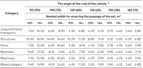
The optimal radii of the corners on intersections were determined by using s created vehicle in the AutoTURN program and with the help of created and vehicles from the program EasyTRACK. The determination of the parameters of the corners was done by using individual types of vehicles (Table 2). The vehicles rode on the given curve in prescribed angles. These were 90°, 105°, 120°, 135°, 150° and 165° in the direction of the travel of the set. The direct passage was not considered because, at such an angle, the swept path of the set stays the same.
During the passage of the vehicles, individual radii of the corners by the respective swept paths were determined. The given radii of corners are used as a simple arc, or the radius is used to determine the complex arc of the intersection. It considers the corners of the level crossings (cross-intersections, T-sections) and the usage of determined radii of the corners on entrance/exit part of the roundabouts. The maximum width of the swept path was also recorded. This width of the swept path determines the necessary width of space to ensure the passage of the set on the road. Some values were calculated mathematically for verification (Krivda & Petru, 2016).
From such verified swept paths was created the resulting Table 3 of the values of radii of the corners. The angles of the raid of the vehicle were used. The table shows the minimum and recommended radii of the corners concerning the angles of the raid. For designing the intersection, it is possible to use the minimum radius of the corner. These values are recommended to be used only in reasonable cases on less frequently used intersections on routes of the oversized and excessive cargos.
20 19/14 (3)
are again recommended to be used only in reasonable cases on less frequently used intersection on routes of excessive or oversized cargos.
Table 3. Results of values of radii of corners
Category
The angle of the raid of the vehicle, °
90 (90) 105 (75) 120 (60) 135 (45) 150 (30) 165 (15)
The radius of the corner R, m
min rec. min rec. min rec. min rec. min rec. min rec.
Long and heavy
transports 14 17 19 22 30 35 39 46 92 95 160 175
Structures 27 30 34 36 50 52 70 73 115 120 165 185
Parts 14 18 19 30 30 38 39 54 92 95 160 180
Machines 15 18 22 24 34 35 45 49 92 95 165 180
Machinery 14 18 19 30 30 38 39 54 92 95 160 175
Mixed category 15 30 22 36 34 52 45 73 92 120 165 185
Note: (*) in the brackets, there are stated the angles for the calculation to 180°.
Table 4. Results of the values of width of the corners
Category
The angle of the raid of the vehicle, °
90 (90) 105 (75) 120 (60) 135 (45) 150 (30) 165 (15)
Needed width for ensuring the passage of the set, m*
min rec. min rec. min rec. min rec. min rec. min rec.
Long and heavy
transports 7.20 10.20 6.30 8.90 5.30 6.80 4.70 6.10 3.70 4.40 3.40 3.80
Structures 15.00 16.90 14.40 14.60 10.70 11.20 8.80 9.10 6.10 6.20 4.30 4.80
Parts 7.20 12.50 6.30 10.60 5.30 8.10 4.70 7.00 3.70 4.70 3.40 3.90
Machines 9.40 11.20 8.10 9.60 6.10 7.30 5.50 6.30 3.90 4.40 3.40 3.70
Machinery 7.20 12.50 6.30 10.60 5.30 8.10 4.70 7.00 3.70 4.70 3.40 3.90
Mixed category 9.40 16.90 8.10 14.60 6.10 11.20 5.50 9.10 3.90 6.20 3.40 4.80
the Parameters for Ensuring Passage of Oversized Cargos
Conclusions
The article describes a part of the results of long-term research, which were conducted to ensure the passage of oversized and excessive cargos on roads in the Czech Republic. The library of vehicles was created to determine and verify the parameters of the existing or the designed roads and intersections. The parameters to ensure the passage of oversized cargos on roads were determined. These parameters are used by the transporters of oversized and excessive cargos, but also by designers of transport constructions within the scope of their activity. Also, the national regulations are processed so that they meet the results of the research. It is also important to note that these vehicles and suggested parameters are used by other countries.
For comparison, the determined parameters for the Czech Republic (the values based on 519 oversized cargos) were compared to transports realised in Slovakia (556 oversized cargos). It was found out that the values determined for the Czech Republic meet the parameters of transports of oversized and excessive cargos done in Slovakia.
Because the roads are continuously developing, there also emerge intersections on backbone routes of oversized cargo. It also includes e.g. turbo-roundabout. There are only eleven turbo-roundabouts in the Czech Republic, but others are being designed. The authors of this paper focus on the analysis of the passage of the oversized and excessive cargos through this type of intersection.
Acknowledgement
The work was supported from the sources for conceptual development of research, development and innovations for 2017 at the VSB−Technical University of Ostrava, which were granted by the
Ministry of Education, Youths and Sports of the Czech Republic.
REFERENCES
Bazaras, D., Batarlienė, N., Palšaitis, R., & Petraška, A. (2013). Optimal Road
Route Selection Criteria System for Oversize Goods Transportation, The Baltic Journal of Road & Bridge Engineering 8(1): 19-24. https://doi. org/10.3846/bjrbe.2013.03
DHV Environment and Transportation (September, 2005). Sustainable Safe Road Design: a Practical Manual, World Bank/Sustainable safe road design. 218 p. European Commission Directorate General for Energy and Transport (2006).
20 19/14 (3)
Forschungsgesellschaft für Straßen-und Verkehrswesen. (2005). Handbuch für die Bemessung von Straßenverkehrsanlagen: HBS. FGSV-Verlag. (in German) Krivda, V., & Petru, J. (2016). Hodnoceni stavebnich prvku krizovatek s vyuzitim
video analyzy. Ostrava: VSB−Technicka Univerzita Ostrava, Česká republika,
184 p. Monografie. (in Czech)
Laitinen, K., Stenman, P., Heikkilä, K., & Väätäjä, M. (2013). Etelä, ja keski-pohjanmaan tuulivoima ja erikoiskuljetukset. Ramboll. 61 p. (in Finnish)
Nyrhinen, E., & Gröndahl, S. (2007). Vaasan tiepiirin alueen kiertoliittymät. Vaasan tiepiiri 40, 88 p. (in Finnish)
Petru, J. (2012). Vlecne krivky navrhoveho vozidla nadmerne prepravy. Studentsky projekt Ostrava: VSB-Technicka univerzita Ostrava, Ceska republika. (in Czech)
Petru, J. (2013). Mobilni kamera pro dopravni a stavebni pruzkum. Studentsky projekt Ostrava: VSB-Technicka univerzita Ostrava, Ceska republika. (in Czech)
Petru, J. (2014). Prujezd nadmernych preprav v prostoru krizovatek. Disertacni prace. Ostrava: VSB-Technicka univerzita Ostrava, Ceska republika. (in Czech)
Petru, J., Krivda, V. (2017). Height and Width Parameters for Ensuring Passage of Excessive Loads on Roads. Acta Polytechnica, 57(3): 209-217. https://doi. org/10.14311/AP.2017.57.0209
Setälä, H. (2003). Erikoiskuljetustoiminta tienpitäjän näkökulmasta. Tiehallinto 3, 142 p. (in Finnish)