TECHNICAL UNIVERSITY OF CLUJ-NAPOCA
ACTA TECHNICA NAPOCENSIS
Series: Applied Mathematics, Mechanics, and Engineering Vol. 62, Issue IV, November, 2019
THE DESIGN AND IMPLEMENTATION OF A MEDICAL INJECTION
SYSTEM PROVIDING SENSITIVE FLUID FLOW CONTROL USING
MECHATRONICS DESIGN METHOD
Sezgin ERSOY, Özgür YILMAZ
Abstract: This paper describes design and implementation of a medical injection device providing sensitive flow control using mechatronics design method. With the ever-increasing demand for sensitive fluid flow control in medical designs, and as fluid flow control technology falls further behind, sensitive fluid flow control is becoming critically important to various medical fluid injection systems. So there is a need to design a medical injection system providing sensitive fluid flow control. To fulfill this purpose, mechatronics design method has been used. There is a synergy in the integration of mechanical, electrical, and computer systems with information systems for the design and manufacture of products and processes in mechatronics design method. After design process the prototype is a system reducing mistakes depending on human, carried out pre-determined operating range, as a central management by the LabVIEW-based. The experimental results of the prototype show that the system has provided the expected design targets. Key words: Mechatronics Design Method, Medical Device, Control, Injection
1. INTRODUCTION
The paper has to offer the answers for the following questions: description of the problem, what is done by other people, what the authors did, what is new, what is my contribution? The accuracy, reliability,
sustainability and followability are
indispensable features in the health sector. These features may only be provided by following the cutting-edge technology in health technology products. Although the computing systems are generally thought to be composed of software and hardware components, they are composed of software, hardware and human components [1-4]. The devices produced with the traditional methods to the date are the products delivering solutions technologies in the health sector. However, the features such as the basic accuracy, reliability, sustainability and followability expected from the devices in the health sector are now in a state that cannot be covered by the devices produced with the traditional design method. These features expected from the devices in the health sector
may only be covered by the new design methods. One of the new designs is Mechatronics Design Method.
The word mechatronics has gained its contemporary usage by providing a focus point and title which joins the electronic equipment (hardware) and computer software with mechanical engineering for a product or process [5]. Mechatronics is a method used for the optimal design of the electronic products. The method is a collection of the applications, procedures and rules which are used by employees in a particular branch of a science and other disciplines.
As a result of this definition the mechatronics system is: an integrated approach which covers the subjects of four disciplines and between disciplines such as electrics, machine, computer science and knowledge technology [6, 7].
and easier-to-use technologies since they are subject to an intensive tempo and long working hours.
Nowadays, when professional responsibility and accountability have been a basic expectation, the new approaches have become a must in order that the health system and nursing profession could support taking clinical decision with evidence-based knowledge [6, 7]. The Mechatronic Design Method has been applied in this study to meet the increasing expectations for the devices of the injection/infusion systems that have been designed with the traditional design method and, and are currently used. There are some constraints of the infusion pumps used now.
The current infusion pumps with simple mechanism are single-user systems and have control just on the unit. In turn, the new system manufactured with the Mechatronics design method each separate injector can provide liquid content according to the parameters such as time, speed, rate and process.
Furthermore, the user interfaces of the current pump systems are relatively complex. Performing the complex processes with the new design has been achieved; and the user has been provided to easily understand and control the conducted procedures easily.
In addition, every unit may be integrated with another unit. In this way, the desired liquid may be given to the patient in communication with the other units, in the case of the patient should be given more than one kind of medicine.
Every unit is able to carry out its working algorithm by using the information from another unit. The software part of the application in computer has been carried out through LabVIEW, a graphical programming language.
2. MECHATRONICS DESIGN
The engineering branch known as System Engineering uses the synchronous approach for the first design [6].
According to this meaning mechatronics can be thought as the extended system engineering approach. However, mechatronics is supported with information systems in order to set light to
the design and to render the whole design more comprehensive and is not only applied to the first stage of the design but also to all the stages.
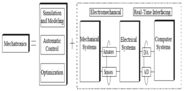
There is a synergy in the whole of electrical and computer systems as well as the information systems to produce products and procedures and design.
Synergy is produced with the right combination of the parameters, which means the last product can be better than all the parts.
Mechatronics parts used to show
performance characteristics which were difficult to achieve without synergy combination. The basic components of mechatronics design are shown in Fig. 1.
Fig. 1. Basic Components of Mechatronics Design Although the literature has adopted this essential/genuine representation, a clearer but more complicated representation is shown in Fig. 2.
3. APPLICATION OF THE TECHNIQUE TO THE MEDICAL INJECTION SYSTEM
It is the control of linear peristaltic injection pump through the perfusion devices (injection pumps) micro controller. Thanks to this, an accurate flow of the liquid is provided. The pump mechanism used in the system is driven by a step engine.
The perfusion devices provide a liquid flow without any contact between the liquid and the pump mechanism. Although there are some types of peristaltic injection pump, the linear peristaltic pump with 3 injection reservoirs have been used in this study (Fig. 3). With the control of the step engine that drives the pump, the liquid flow speed can be accurately controlled [9].
Fig. 3. Accurate Liquid Flow Control with three Terminals
In biomedical field, the controlled medicine release to the patient can be achieved in various ways. For example, the perfusion devices (injector pumps), elastomeric pumps, osmotic pressure-control medicine release, nanogels and etc. The system established in our study offers a structure that will be able to work as an artificial heart in open-heart operations excluding controlled drug release in biomedical field, or to be used in diabetes devices. Apart from this, the system has an architecture allows to be used in other sectors such food (milk analyzers, water analyzers), chemical, paint.
In designing these devices that can be planned according to the job to be carried out, the mechanical part and the control unit may vary according to the task. For example, the injector pumps are used for low-dosage applications, while the peristaltic pumps are used in high-dosage applications.
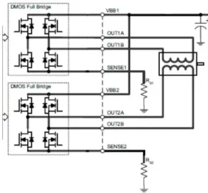
Multi-rotary peristaltic pumps are used in chemical applications while linear peristaltic or injector pumps are preferred in medical application. In this study, the liquid flow has been provided through linear peristaltic injector pump. The user interfaces and pump control tasks have been carried out through STM32, the micro-controller; while the central console system has been established through the software LabVIEW. The step engines used in the accurate liquid flow control unit with three terminals are controlled with the driver circuit shown in Fig. 4 [10].
Fig. 4. The explicit scheme of the Engine Control Circuit [11, 12]
The number of the injector reservoirs of the accurate liquid flow control device that is designed as an injector with three reservoir in the prototype design may be increased if one would like to mix more than three liquids. The pitch of the liquid injector reservoirs can be adjusted through the user interface optionally by increasing or decreasing the speed of the engine.
In addition, the injector liquid reservoirs may be provided to go ahead the memory of according to the time. Since the accurate liquid flow device has been planned as with three reservoirs (injectors) in the prototype design, the memory of the control panel has been preferred accordingly.
injector reservoirs are needed, a decision should be made after a programming in accordance with the number of the used liquid injector reservoir and an evaluation includes if the control panel memory complies with the system or not.
In the designed multi-terminal accurate liquid-flow control device, three micro-step engines have been used. Every engine is connected to the threaded rod that provides the linear motion in clutching method. There is an injector holder before every system.
The circular motion provided from the engines is transferred to the linear motion via clutching. The circular motion transferred to the system provides a linear motion to the injector within the injector’s ejector.
Thanks to this, the injector’s ejector applies pressure to the push- part of the injector and the accurate liquid flow will be provided.
3.1 Control Unit Determination
The MINI-STM32 control circuit has been used in the application. On MINI-STM32, there are a SD-Card, USB, RS-232 and touch- operated 3.2" TFT LCD.
Fig. 5. MINI-STM32 Circuit
On the MINI-STM32 circuit, there are a 32-pin connector for LCD connections, a 20-32-pin JTAG connector for programming and a 26-pin connector for general input-out processes. In addition there are 2 butons, 2 user-controlled LEDs, 1 potentiometer, the battery housing for RTC applications, a MAX232 integrated circuit for RS-232, and the active and passive components required for driving the micro-controller.
3.2 The Touch Screen
The control on the MINI-STM32 is provided through a touch-operated TFT-LCD screen
interface found on the circuit. This screen allows carrying out operations such as entering the desired parameters into the system and viewing the injection process apply to the patient etc.
In addition, there is a SD-Card housing on the LCD drive card. In this way, the high-volume reports regarding the injection process are stored through SD-Card without computer connection.
3.3 Designing the User Interface with the Software
The LabVIEW graphical programming language is the software that was produced by the National Instrument firm; and it is used in integration with various types of hardware, providing very accurate measurements in the processes of data collection, analyzing and presentation.
The LabVIEW, GPL has a symbolized command set instead of text-based coding.
Therefore; the difficulty to memorize the commands has been removed. The programmer may produce the software such as establishing a flow chart, by taking the needed functions from the pallets [13, 14].
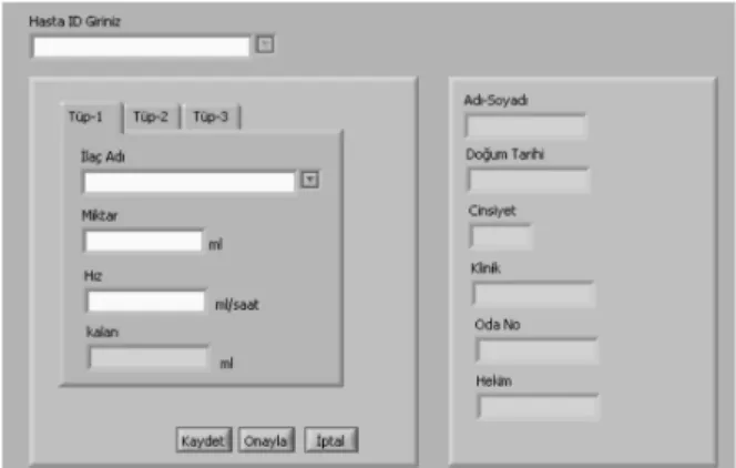
Fig. 6. The System Interface Designed in LabVIEW The user interface shown in Fig. 6 runs on the master computer, into which various identity information can be entered and through which all three tubes on the accurate liquid flow control device can separately be controlled.
drug in the desired amount and speed. The number of the accurate liquid flow control devices may optionally be increased and the LabVIEW interface program can communicate with the new added units. The LabVIEW interface program also presents a reporting choice.
4. CONCLUSION
The operations in health sector are mainly carried out with labor force. Since the medicine grounds on human and the human being have complex structure, the errors become inevitable and therefore the influence the patient safety.
The studies in the biomedical device design field aim to probe the components, systems and human-machine system relations that focus on human and lead human errors; to apply preventive and corrective approaches; minimizing the risks [15].
The perfusion devices come first among the devices in which human-related errors often occur in the health sector. In this study, an accurate liquid flow control device has been designed by using Mechatronics Design Method in order to minimize the human-related errors.
This independent-structured injector, which has been developed in scope of this study and designed with the Mechatronic Design Method, provides savings in time, speed, rate and process and minimizes human-related errors.
Thanks to this system which provides ease for the users and has user interface, the desired liquid may be given to the patient in communication with the other units, in the case of the patient should be given more than one kind of drugs.
Every unit is able carry out its working algorithm by using the information from another unit.
With this study, a Biomedical Device with high accuracy competence has been designed with Mechatronics Design Method to allow the patients to be given more than one types of liquid in a controlled manner and minimize the human errors.
5. REFERENCES
[1] Sezgin Ersoy; “Seminer Notes for Automotic Controle”; TMMO 2009,
İstanbul.
[2] Lorenzi NM. New York Springer Verlag 1995.
[3] Braude R M. People and Organizational Issues in Health Informatic. J. Am Med Inform Assoc. 1997 Mar Apr 4(2): 150 -151.
[4] N. Zayim; “Technological Change
Management in Medical Informatics: Human and Organization Issues”; 2. Nationa Medical Congrees / Medical Informatics; pp: 73; 2005 Turkey.
[5] A. Erden, Mechatronics Design;
Principles and Innovations in Design Engineering.
[6] http://design.me.metu.edu.tr/me462/Pape rs/Endüstri&Otomasyon-03.pdf (Access Date: November 2002).
[7] S. Devdas; R.A. Kolk, in: Mechatronics System Design, PWS Publishing, Boston, 2-3 (1997). http://design.me.metu.edu.tr/ m00000e462/Papers/Endüstri&Otomasy on-01.pdf (Access Date: November 2002)
[8] M. B., Histand,; D. G., Alciatore, in: Introduction to Mechatronics and Measurement Systems, McGraw Hill Inc., 1999.
[9] M. Çetinel, in: Mühendisliğin Yeni
Adresi: Mekatronik, Mühendis ve Makina Dergisi, Sayı: 489, Cilt: 41, 29-31, Ekim 2000.
[10] http://www.tradekey.com/product_view/
id/834020.htm (Erişim tarihi:
01.09.2010)
[11] DAQBOARD-2000 Series User Guide, IOtech Inc.
[12] A3982 DMOS Stepper Motor Driver with Translator, Data Sheet, Allegro Micro Systems, Inc.
[13] http://www.e3tam.com/temsilcilikler/ni/l abview.htm (Erişim tarihi: 01.09.2010)
[14] Information on http://www.ni.com
(Access Date: November 2007).
Application Examples in the Field of Patient Safety, Beta Publisher. Istanbul 2012.
PROIECTAREA ȘI PUNEREA ÎN APLICARE A UNUI SISTEM DE INJECȚIE MEDICALĂ
FURNIZAREA DE CONTROL AL FLUXULUI FLUID SENSIBIL FOLOSIND METODA DE PROIECTARE MECHATRONICS
Rezumat: Această lucrare descrie proiectarea și punerea în aplicare a unui dispozitiv de injecție medicală care oferă un control sensibil al fluxului folosind metoda de proiectare Mecatronică. Cu cererea tot mai mare de control al fluxului de fluid sensibil în modele medicale și ca tehnologia fluxului de lichid de control scade în continuare înapoi, controlul fluxului de fluid sensibil devine extrem de important pentru diferite sisteme de injecție de lichide medicale. Deci, există o nevoie de a proiecta un sistem de injecție medicală furnizarea de control al fluxului de fluid sensibil. Pentru a îndeplini acest scop, metoda de proiectare Mecatronică a fost folosită. Există o sinergie în integrarea sistemelor mecanice, electrice și informatice cu sisteme informatice pentru proiectarea și fabricarea de produse și procese în metoda de proiectare Mecatronică. După procesul de proiectare prototipul este un sistem de reducere a greșelilor în funcție de om, a efectuat pre-determinate gama de operare, ca un management central de LabVIEW-based. Rezultatele experimentale ale prototipului arată că sistemul a furnizat obiectivele de proiectare preconizate.
Sezgin ERSOY, Assoc. Prof. Marmara University Technology Faculty Mechatronic Engineering, [email protected], +902163365770-1671.