Unit-2
Network Models & Protocol
Suite
Contents
Layered Tasks
The OSI Model
Layers in OSI Model
TCP/IP Protocol Suite
LAYERED TASKS
LAYERED TASKS
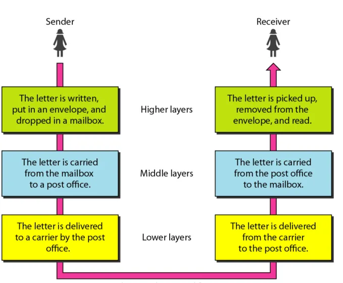
We use the concept of
We use the concept of layers
layers
in our daily life. As an
in our daily life. As an
example, let us consider two friends who communicate
example, let us consider two friends who communicate
through postal mail. The process of sending a letter to a
through postal mail. The process of sending a letter to a
friend would be complex if there were no services
friend would be complex if there were no services
available from the post office.
THE OSI MODEL
THE OSI MODEL
Established in 1947, the International Standards
Established in 1947, the International Standards
Organization (
Organization (ISO
ISO
) is a multinational body dedicated to
) is a multinational body dedicated to
worldwide agreement on international standards. An ISO
worldwide agreement on international standards. An ISO
standard that covers all aspects of network
standard that covers all aspects of network
communications is the Open Systems Interconnection
communications is the Open Systems Interconnection
(
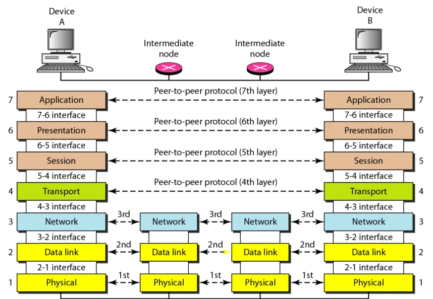
LAYERS IN THE OSI MODEL
LAYERS IN THE OSI MODEL
The different layers of the OSI Model
The different layers of the OSI Model
are:-Physical Layer
Data Link Layer
Network Layer
Transport Layer
Session Layer
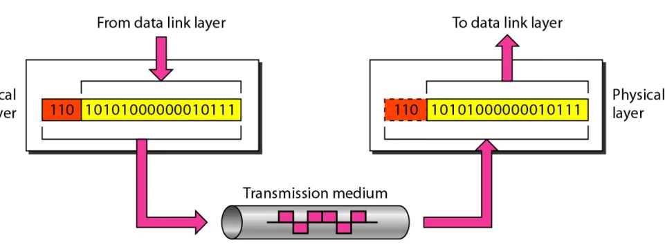
Figure 2.5 Physical layer
Task of Physical Layer
• Physical Characteristics of Interfaces & Medium:- it defines the
characteristics of the interface between the devices and the transmission medium. It also defines the type of transmission medium.
• Representation of Bits:- The physical layer define the type of encoding
( how 0’s & 1’s are changed to signals)
• Data Rate:- The physical layer defines the transmission rate of data.
• Synchronization of Bits:- The sender and receiver clocks must be
synchronized. The sender & receiver must use the same bit rate.
• Line Configuration:- The physical layer is concern with the connection
of device to the media i.e. point to point or multi point configuration.
• Physical Topology:- it defines how the devices are physicaly connected
i.e. mesh, ring, star, bus etc.
• Transmission Mode:- it defines the direction of transmission between
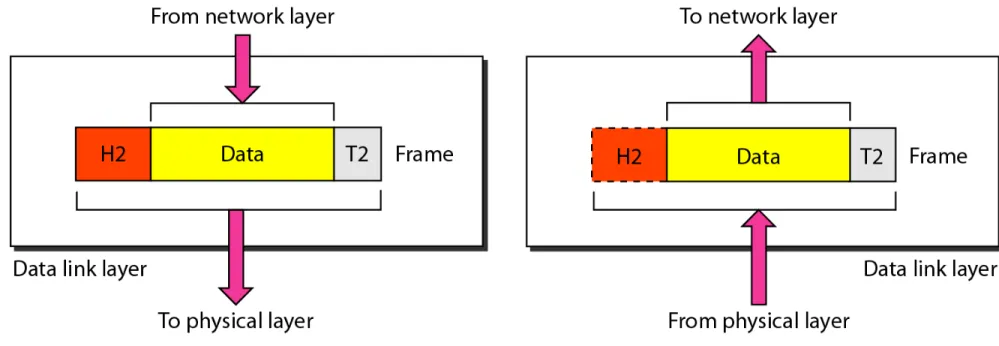
Figure 2.6 Data link layer
Task of Data Link Layer
• Framing:- The data link layer divides the stream of bits received from
the network layer into manageable data units called frames.
• Physical Addressing:- If the frames are to be distributed to different
systems on the network, the data link layer adds a header to the frame to define the sender and/or receiver of the frame. If the frame is intended for a system outside the sender’s network, the receiver address is the address of the device that connects the network to the next one.
• Flow Control:- The data link layer imposes a flow control mechanism. • Error Control:- The data link layer add mechanism to control the
errors. It is normally achieved through a trailer added to the end of the frame.
• Access Control:- when two or more devices are connected to the same
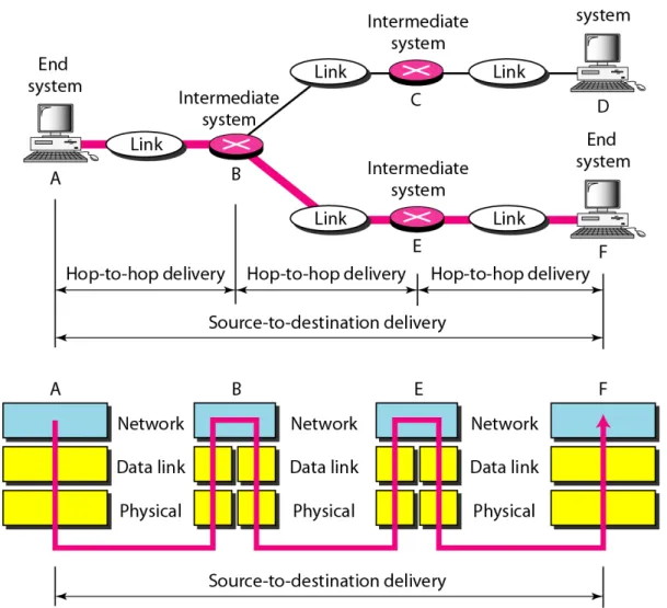
Figure 2.8 Network layer
Task of Network Layer
• The network layer is responsible for the source to destination
delivery of a packet, possibly across multiple networks (links).
• Whereas the data link layer ensures the delivery of packets
between two systems on the same network, the network layer ensures the delivery of packet from source destination to final destination.
• When independent networks or links are connected to create
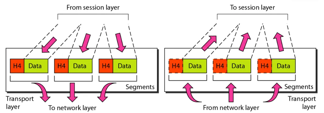
Figure 2.10 Transport layer
Task of Transport Layer
• Service Point Addressing:- Computers often run several programmes at
the same time. For this reason, source to destination delivery means delivery not only from one computer to the next but also from a specific process on the other. The transport layer header must therefore include a type of address called source to destination address. The network layer gets each packet to the correct computer; the transport layer gets the entire message to the correct process on that computer.
• Segmentation & Reassembly:- A message is divided into transmittable
segments, with each segment containing a sequence number. These numbers enable the transport layer to reassemble the message correctly upon receiving at the receiver.
• Connection Control:- it may be connection oriented or connection less. • Flow Control:- It is responsible for end to end flow control.
• Error Control:- It is responsible for process to process error control.
Figure 2.12 Session layer
Task of Session Layer
• Dialog Control:- it allows the two system to enter into a dialog. It
allows the communication between two processes to take place in either half duplex or full duplex.
• Synchronization:- the session layer allows a process to add
Figure 2.13 Presentation layer
Task of Presentation Layer
• Translation:- Because different computers use different encoding
systems, the presentation layer is responsible for interoperability between these different encoding methods. So the presentation layer at the sender changes the information from its sender-dependent format into a common format. The presentation layer at the receiving machine changes the common format into its receiver –dependent format.
• Encryption:- It means that the sender transforms the original
information to the another form and sends the resulting message out over the network. Decryption reverses the original process to transform the message back to its original form.
• Compression:- It reduces the number of bits contained in the
Figure 2.14 Application layer
Task of Application Layer
• Network Virtual Terminal:- It is a software version of a physical
terminal, and it allows a user to log on to a remote host.
• Mail Services:- it provides the basis for email forwarding and storage. • File Transfer, Access and Management:- This application allows a
user to access files in a remote host, to retrieve files from a remote computer for use in the local computer.
• Directory Services:- this application provides distributed database
TCP/IP PROTOCOL SUITE
TCP/IP PROTOCOL SUITE
The layers in the
The layers in the TCP/IP protocol suite
TCP/IP protocol suite
do not
do not
exactly match those in the OSI model. The original
exactly match those in the OSI model. The original
TCP/IP protocol suite was defined as having four
TCP/IP protocol suite was defined as having four
layers:
layers: host-to-network
host-to-network
, internet
,
internet
, transport
,
transport
, and
, and
application
application
. However, when TCP/IP is compared to
. However, when TCP/IP is compared to
OSI, we can say that the TCP/IP protocol suite is
OSI, we can say that the TCP/IP protocol suite is
made of five layers:
made of five layers: physical
physical
, data link
,
data link
, network
,
network
,
,
transport
Physical & Data Link layers:- At this layer, TCP/IP does not define any specific protocol. It supports all the standard protocols. A network in a TCP/IP internetwork can be a local-area network or wide area network.
Network Layer:- At the network layer ( or, more accurately, the internetwork layer), TCP/IP supports the internetworking protocol. It uses four supporting protocols: ARP, RARP, ICMP & IGMP.
Internetworking Protocol (IP):- it is the transmission mechanism used by the TCP/IP protocols. It is an unreliable and connectionless protocol. IP provides no error checking or tracking mechanism. IP use Datagram approach to transport the packet from source to destination.
Reverse Address Resolution Protocol (RARP):- this protocol allows a host to discover its internet address when it knows its physical address. It is used when computer is connected to a network for first time.
Internet Control Message Protocol (ICMP):- it is a mechanism used by host and gateways to send notification of datagram problems back to the sender. It sends query and error reporting messages.
Internet Group Message Protocol (IGMP):- it is used to facilitate the simultaneous transmission of a message to a group of recipients.
Transport layer:- it is responsible for delivery of message from a process to another process. It is represented by two protocols:- UDP & TCP.
User Datagram Protocol (UDP):- it is a process to process protocol that adds only port addresses, checksum error control, and length information of data from upper layer.
Transmission Control Protocol (TCP):- TCP is a stream transport protocol i.e. connection oriented. In this a connection is established between both the ends before data transmission.
At the sending end TCP divides a stream of data into smaller units called segments. Each segment includes a sequence number for reordering after receipt, together with ack. no. for the segments received.
At the receiving end, TCP collects each datagram as it comes in and reorder the transmission based on sequence no.
Stream Control Transmission Protocol:- it provides support for newer applications such as voice over the internet. It combines the best features of UDP & TCP protocol.
ADDRESSING
ADDRESSING
Four levels of addresses are used in an internet employing
Four levels of addresses are used in an internet employing
the TCP/IP protocols, these
the TCP/IP protocols, these
are:--Physical Addresses
Logical Addresses
Port Addresses
Physical
Addresses:-•The physical address is also known as the link address, is the
address of a node as defined by its LAN or WAN.
•It is included in the frame used by the data link layer. •It is the lowest level address.
•The physical address have the authority over the network (LAN &
WAN). The size and format of these addresses vary depending upon the network.
•For eg. Ethernet uses a 6 byte (48 bits) physical address that is
In Figure 2.19 a node with physical address 10 sends a frame to a
node with physical address 87. The two nodes are connected by a
link (bus topology LAN). As the figure shows, the computer with
physical address
10
is the sender, and the computer with physical
address
87
is the receiver.
Example 2.1
Logical
Addresses:-•Physical addresses are not adequate in an internetwork environment
where different networks have different address formats.
•A universal addressing system is needed in which each host can be
identified uniquely, regardless of the type of physical network.
•The logical addresses are designed for this purpose and they are
independent of physical network.
•A logical address in the internet is currently 32 bit address that can
uniquely defined a host connected to internet.
•No two publicly addressed and visible hosts on the internet have
Port
Addresses:-•The IP Address and the physical address are necessary for a quantity
of data to travel from a source to the destination host. However, the arrival of data at the destination is not the final objective.
•Today computers are devices that can run multiple processes at the
same time.
•For theses processes to receive data simultaneously, there is need of of
method to label the different process.
•So the function of addressing a particular process is called as port
addressing.
Specific
Addresses:-•Some applications have user friendly addresses that are designed for
that specific address.
•The example includes the email address ( for eg. [email protected]) and
the universal resource locator (URL) (for eg. google.com).
•The first defines the recipient of an email and the second is used to