1
SHORT RUN BOX MAKER
A Senior Project submitted to
the Faculty of California Polytechnic State University, San Luis Obispo
In Partial Fulfillment
of the Requirements for the Degree of Bachelor of Science in General Engineering
by
2
3 Abstract
Small businesses with short run product catalogs have trouble finding the right size box that will work for multiple products. In turn, this leads most businesses to use oversized boxes resulting in unnecessary shipping fees. The objective of this project was to develop and test a cost-effective prototype of a box making machine that could create a short run of custom sized boxes. A Co2 laser was found to be the best option for cutting cardboard and a vertically standing machine was designed to feed the cardboard via rollers. To control cardboard movement stepper motors were used and controlled using an Arduino Uno. A User Interface (UI) was developed using Excel VBA to communicate with the Arduino Uno and to pass on box size and type. The prototype proved to be effective in cutting cardboard patterns. Testing revealed the prototype could be twice as fast as manual cutting methods if an 80W laser tube or larger were used. The source code used to build this project serves as a good reference for future needs of accurate stepper motor movement and PC UI development.
Keywords: Cardboard, Laser, Cutting, Box, Making, Arduino, Uno, Excel, VBA, UI
ACKNOWLEDGMENTS
4
LIST OF TABLES
Table 1: Cutting method decision matrix ... 14
Table 2: Average coefficients of friction between cardboard and sandpaper ... 25
Table 3: Coefficient of Friction of Cardboard and Sandpaper Test Results ... 33
Table 4: Cutter Drag Force Test Results ... 33
LIST OF FIGURES Figure 1: The standard box pattern (Wybenga, 2013, p. 470) ... 6
Figure 2: Estimated number of packages to be shipped in 2019... 7
Figure 3: Fishbone diagram of the problem. ... 8
Figure 4: Cardboard manufacturing process (Wybenga, 2013, p. 462) ... 9
Figure 5: Most common cardboard structures (Wybenga, 2013, p. 463) ... 9
Figure 6: Sample flute types (Not to scale) (Wybenga, 2013, p. 462) ... 10
Figure 7: Most common paper types (Daggar, n.d.) ... 10
Figure 8: Sample box pattern (Wybenga, 2013, p. 467) ... 11
Figure 9: Box certificate example (Wybenga, 2013, p. 465) ... 11
Figure 10: UPS strength guidelines (Uline) ... 12
Figure 11: Space comparison of shop floor between a gantry layout and large format printer layout. ... 13
Figure 12: A comparison between electric and pneumatic actuators ... 15
Figure 13: Cardboard feeder design decision ... 16
Figure 14: Early concept designs ... 17
Figure 15: Assigned pins for the SRBM project ... 19
Figure 16: State Transition Diagram for the SRBM ... 20
Figure 17: Serial Communication Format ... 20
Figure 18: Excel User Interface ... 21
Figure 19: Diagram of cutter drag force experiment ... 23
Figure 20: Experiment apparatus used to measure cutter drag force ... 23
Figure 21: Relationship between maximum angle and coefficient of friction ... 24
Figure 22: Experimental apparatus used to find the coefficients of friction ... 24
Figure 23: Proof of concept prototype used to verify proper function of design ... 26
Figure 24: Bending of cutter due to excessive cutting pressure ... 26
Figure 25: A slot that was added to raise the cardboard higher onto the blade. ... 27
Figure 26: Final Machine Design ... 28
Figure 27: Final Design Prototype ... 29
Figure 28: Close up view of final design prototype ... 30
Figure 29: Initial Prototype Stepper Motor Driver State Transition Diagram ... 34
5
Introduction: ... 5
Problem Description: ... 6
Literature Review: ... 8
Solution Design: ... 12
Test and Evaluation of Design Alternatives ... 22
Conclusions and Recommendations ... 31
Future Directions ... 32
References ... 32
Appendix: ... 33
1. Coefficient of Friction Test Results ... 33
2. Cutter Drag Force Test Results ... 33
3. Initial Prototype Stepper Motor Driver ... 34
4. Initial Protype Hand Calculations for Linear Bearings Selection ... 40
5. Initial Prototype CAD Model of Carriage Assembly ... 41
6. Excel VBA UI Source Code ... 45
7. ISR Hand Calculations ... 46
8. SRBM Final Prototype Source Code ... 48
9. Final Prototype CAD ... 66
Introduction:
As the owner of a small short run furniture manufacturing business by the name of
Central Coast Creations, I’m constantly faced with the issue of finding the right size box
for the products I sell. As a result, many custom size boxes are hand made from large 4’ x
8’ sheets using steel blades, the process is both time consuming and costly. Based on 15
sample boxes made it took an average time of 8.2 min. It’s estimated by sales that by the
end of 2019 a total of 107 hours and $2,130 (at a rate of $20/hr.) would have been spent
making boxes since the business started in 2017. However, scaling this up to a larger
6
be much more significant. In this senior project report, I document my research and
testing of a short run box machine prototype as if it was to be implemented in a business
like mine.
Problem Description:
Currently the method used to make custom sized boxes involves cutting a 4’ x 8’ sheet of
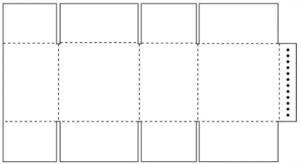
cardboard using a steel blade. A pattern as shown in Figure 1 is cut out to the dimensions
of the box that is to be made. Next, the flaps are folded on an edge of a table and the box
is taped together to its final shape.
Figure 1:The standard box pattern (Wybenga, 2013, p. 470)
Due to the unpredictable shape of the products, most of them being handmade rustic
pieces, a standard box size cannot be implemented for a single product. In addition,
shipping costs for oversized boxes can become expensive if accumulated over a year.
Based on 15 sample boxes that were manually made it took an average time of 8.2 min to
create a box. Using sales data from 2018 as shown in Figure 2 a total of 322 custom
7
the cost of making boxes in 2018 was $880. While not very significant, by the end of
2019 an estimated total of 107 hours and $2,130 would have been spent making boxes.
By accumulating this cost over the span of 5 years with business growth, the problem can
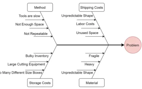
reach a cost of over $10,000. Figure 3 shows a fishbone diagram of the causes of the
problem.
8
Figure 3: Fishbone diagram of the problem.
Literature Review:
To design a solution capable of creating custom sized boxes it was necessary to review
both the cardboard manufacturing processes and test methods. From this knowledge the
best design decisions were made later in the project.
According to Wybenga and Roth (2013) cardboard is made from two paper faces glued to
a corrugated medium center using large glue rollers, this can be seen in Figure 4. While
the figure shows how a single wall corrugated sheet is made similarly double and triple
9
Figure 4: Cardboard manufacturing process (Wybenga, 2013, p. 462)
Figure 5: Most common cardboard structures (Wybenga, 2013, p. 463)
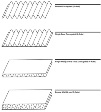
Internally the corrugated medium or flutes as it’s called can vary in pitch and height
depending on the desired structure. The flutes are usually indicated by a letter see Figure
10
can vary depending on its use however, the most commonly used paper is virgin Kraft
paper. For other commonly used papers in the industry see Figure 7.
Figure 6: Sample flute types (Not to scale) (Wybenga, 2013, p. 462)
Figure 7: Most common paper types (Daggar, n.d.)
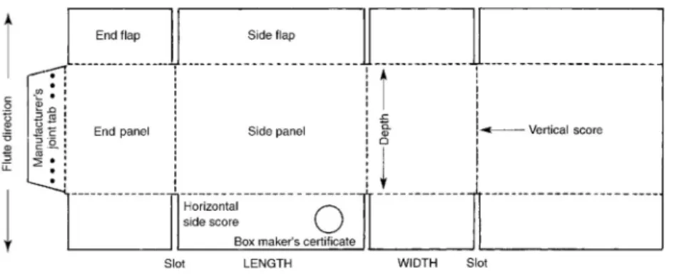
Using cardboard sheets box manufacturers cut cardboard box patterns from them using
large die cutters see Figure 8 for a sample box pattern. For more information on box
11
Figure 8: Sample box pattern (Wybenga, 2013, p. 467)
Usually box manufacturers attach their box certificates at the bottom of the box that
usually contains information regarding weight limits, ECT (Edge Crush Test) results, and
Burst test results. See Figure 9 for an example box certificate.
Figure 9: Box certificate example (Wybenga, 2013, p. 465)
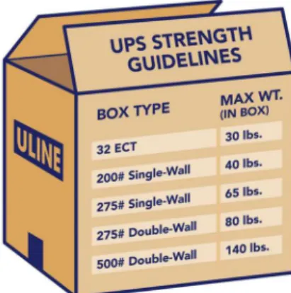
Box manufacturers attach max weight limits before failure however, a safer threshold is
desired to avoid shipping damages. Using UPS (United Parcel Service) strength
guidelines the maximum shipping weight can be determined using the cardboard
classification. See Figure 10 for UPS strength guidelines. Since this project is aimed
towards small business owners using the most cost-effective solution and readily
12
one being a single wall of ECT 40 and a burst strength of 200 psi as well as a double wall
of ECT 48 and a burst strength of 275 psi. All other styles of cardboard are either too
expensive to be effectively implemented or not readily available and must be special
ordered.
Figure 10: UPS strength guidelines (Uline)
While researching other custom box machines were found but none that were both cost
effective and implemented automation at a small scale. With a growing number of
custom product sellers in ecommerce there is an increasing need for a solution. If a
solution is implemented buyers can pay less for shipping, and sellers can increase profit
margins.
Solution Design:
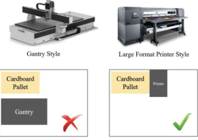
While gathering ideas for how the design of this machine will look like two layouts were
taken into consideration, one being in the form of a gantry machine and the other being in
13
can be less complex to add different tools to the machine. In addition, a gantry machine
would not require a method to feed in the cardboard because most machines such as CNC
(Computer Numerically Controlled) routers use vacuum tables. However, since space is
very important because this project is geared towards small businesses a large format
printer layout is desired. Both layouts would require space for at least one cardboard
pallet and the machine. As shown in Figure 11 a large format printer layout takes
significantly less space when compared to a gantry machine. At a normal market rate of
$1 per square foot for a warehouse lease, the cost for a gantry machine would equate to
$540 a year while a large format printer layout would equate to a quarter of that cost. As
a result, a large format printer layout was decided early on. An early concept of the
design can be found in Figure 14:. However, to further reduce space the final design of the machine resulted in a vertical layout such as to have it laid up against a wall. In practice
this reduces the amount of space that needs to be in front of the machine and creates a
smaller footprint when compared to a large format printer.
14
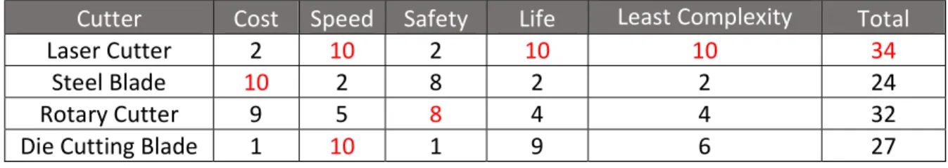
While ideating forms to cut the cardboard and researching cutting methods Mathilde
(2014) was a good source. The following decision matrix was made to compare different
methods. Higher numbers are the most desired aspects such as lowest cost, quickest
speed, highest safety, longest life, and least complexity. All aspects are equally important
and are weighted equally in this decision matrix.
Table 1: Cutting method decision matrix
Cutter Cost Speed Safety Life Least Complexity Total
Laser Cutter 2 10 2 10 10 34
Steel Blade 10 2 8 2 2 24
Rotary Cutter 9 5 8 4 4 32
Die Cutting Blade 1 10 1 9 6 27
Initially it was thought that a rotary cutter would be the best option for this project but
proof of concept testing later revealed that a complex method of holding the cardboard
againts the rotary cutter would be required. As a result, rotary cutters and steel blades
were ruled out as a possible solution. Die cutting blades were considered but were also
ruled out do to the cost of blades they would be out the budget of a low cost soultion.
Additionally, the size of the machine would have to increase to move the blades in and
out of the cutting area this would be an undesirable feature. A laser cutter was found to be
the best choice for this project, because It proved to be the simplest method to cut
cardboad while being a fast solution. The fold edges could be cut using patttern lines to
ease folding while still maintaining the structure of the box. However, the downside to
laser cutting methods would be the fume extraction equiptment needed for safe operation
15
only on the the design of the machine, a fume extraction method was not designed as
there is many products that do this already in the market.
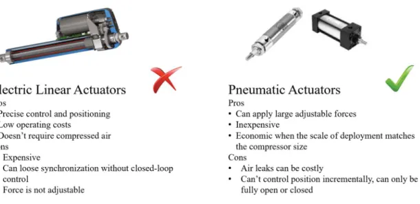
While idealizing ways to feed in the cardboard to the rotary cutter during the initial
concpet design two possible solutions were compared, electric and pneumatic actuators.
After reading a comparison article written by Robert Kral (2015) an engineer for
BIMBA® a major manufacturer of both electric and pneumatic actuators the pros and
cons of each was listed and compared see Figure 12.
Figure 12: A comparison between electric and pneumatic actuators
Due to the need of regulating the force applied by both the rotary cutter and the cardboard
feeder into the cardboard a pneumatic actuator was chosen for the early proof of concept
prototype. Since this project is geared towards small business and shops it ws assumed
that compressed air was readily available. However, do to the project switching its course
16
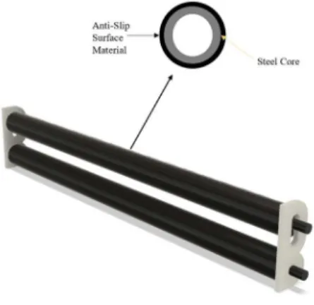
Furthermore, using large format printers as an inspiration large rollers were chosen to
feed the cardboard into the machine an early conecpt design is shown in Figure 13. The
anti-slip surface material was chosen to reduces the possibility of slippage and skipping
of the rollers hence letting the machine cut more accuratly. Testing later revealed
neoprene rubber would be the best material and it was added to the final design. To drive
the rollers a set of spur gears were designed to replicate the number of steps per inch
required for the other axis. As a result, a 13:6 gear reduction created approximately the
same amount of steps per revolution.
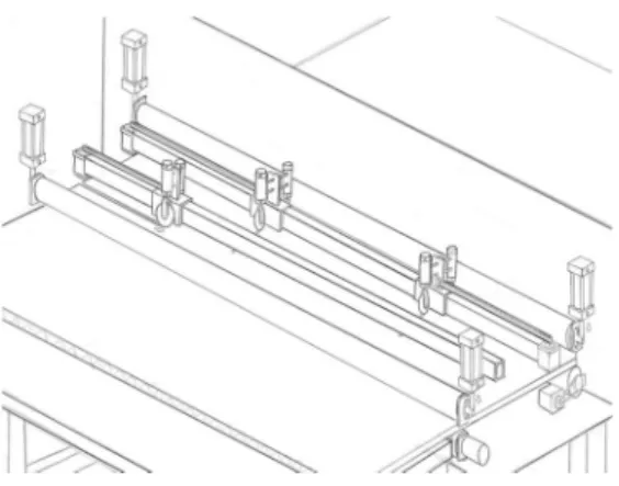
17
Figure 14: Early concept designs
When choosing a laser cutter, a Co2 laser tube was preferred over a laser diode due too their high wattage and fast cutting capability. They are commonly used to cut thin plywood sheets for arts and crafts but can be used to cut a wide range of materials including cardboard. As a result, a 40 W laser tube was chosen for this project. A more powerful laser tube would increase cutting speeds however for the purpose of creating a prototype a 40 W laser tube was determined
sufficient. The mirrors, focal lens, and mirror mounts required for this project were selected using off-the-shelf components. Early on it was determined that the machine would be designed around a 1.5” focal length the frame was designed to work with such lens. In a complete solution a fume extractor such as those used by Co2 laser machines would have to implemented with a hood to contain the fumes.
18
To control stepper motor functions an Arduino Uno was chosen as its clock frequency of 16 MHz was determined to be sufficient to perform the functions of this prototype which included
accurate stepper motor movement. Another feature that was desired was its ability to
communicate with a PC via a USB serial port. This feature would allow the creation of an easy to use PC user interface that could send over the required box dimensions to the microcontroller.
19
Figure 15: Assigned pins for the SRBM project
20
Figure 16: State Transition Diagram for the SRBM
Figure 17: Serial Communication Format
21
Figure 18: Excel User Interface
To smooth out stepper motor operation the pulse width modulation (PWM) required for stepper movement was controlled in an Interrupt Service Routine (ISR) which was programed to loop at 100 Khz the maximum frequency the stepper motor drivers could take according to the data sheet. Controlling the stepper in an ISR would make sure that the PWM was accurate, and without interruption from other controller functions. To be able to control stepper motor speed,
22
Furthermore, the stepper motors were found to vibrate a lot during testing as a quick solution to the problem a 10- step linearly increasing velocity profile was used for both accelerating and decelerating. Vibration was drastically reduced, and it allowed for smoother transitions between movements.
Test and Evaluation of Design Alternatives
Initially rotary cutters were considered for this project and two tests were performed to
validate the proper function of them. One test similar to how a tomodynamometer is used
to measure blade cutting resistance on fabric using ASTM standards (ASTM, 2015)
measures the cutting resistance of the rotary cutter. It also provides different cutting
pressures in the pneumatic cylinder to be able to find the required cutting pressure for
both the single and double walled cardboards. See Figure 19 for a diagram of the
experiment and Figure 20 for the experiment apparatus. Appendix 2 contains the
collected experiment data. It was found that for double wall cardboard (ECT 48) the
cutter drag force peaked at an average of 5.1 lbf and for single wall cardboard (ECT 40)
the drag force peaked at 3.4 lbf. These results will be used later on to size the linear
23
Figure 19: Diagram of cutter drag force experiment
Figure 20: Experiment apparatus used to measure cutter drag force
The next test that was perfomed was used on the cardboard feeder anti-slip surface
materials to find the coefficicent of friction. Using methods outlineds in ASTM standards
(ASTM, 2018) different surface materials were tested for their coefficicents of friction on
cardboard to find a sutible material for the feeder cylinder. See Figure 21 for the
relationshp between maximum angle before slippage and coefficient of friction. See
24
s
Figure 21: Relationship between maximum angle and coefficient of friction
Figure 22: Experimental apparatus used to find the coefficients of friction
After experimenting with a few materials, neoprene rubber was found to have the highest
coefficient of friction, see Table 2. Appendix 1 contains results for the coefficient of
friction tests. Early on it was thought that sandpaper would have been a good option but
due to its roughness and large scratches that were left behind on the cardboard test
surface it was ruled out. From these results neoprene rubber resulted in having an
25
Table 2: Average coefficients of friction between cardboard and sandpaper
Material θmax (⁰) μ
Neoprene Rubber 46 1.0 36 Grit Sandpaper 48 1.1 80 Grit Sandpaper 46 1.0 150 Grit Sandpaper 44 0.97 220 Grit Sandpaper 42 0.89 360 Grit Sandpaper 36 0.73
To verify that the original concept design was going to effectively cut cardboard a simple
carriage proof of concept prototype was built and tested as shown in Figure 23. Next, a
simple program was written in Python and was ran on a Pyboard microcontroller to
activate the pneumatic cylinder using a solenoid as well as to move the stepper motor.
The stepper motor driver can be found in Appendix 3. Through experimentation it was
discovered that the rotary cutter blade was too thin to hold the cutting pressure and flexed
to the point of curving the cutting line as shown in Figure 24. Through experimentation it
26
lowest cutting edge the cutter could make a cut with less effort. To do this a slot was
added along the cutting line as shown in Figure 25.
Figure 23: Proof of concept prototype used to verify proper function of design
27
Figure 25: A slot that was added to raise the cardboard higher onto the blade.
After the proof of concept prototype was built using a rotary cutter it became clear that a
solution using a rotary would need complex methods of holding the cardboard down
against the cutting force. In turn, this led to the decision of using a laser cutter instead.
Such design would not require pneumatic cylinders and would use significantly fewer
moving parts.
Furthermore, the machine shown in Figure 26 was designed to feed in the cardboard vertically into the laser cutter. The wheels laying outside the machine were designed to
feed in the cardboard sheet as straight as possible. They remain unattached to the vertical
28
Figure 26: Final Machine Design
A prototype of this design was built and can be seen in Figure 27 a close up view can be seen of the front in Figure 28. The microcontroller was thoroughly tested for proper functionality. The machine was found to move the cardboard accurately and all button
functions worked properly. However, due to improper concentricity of the roller ends to
the centers the cardboard was found to slip slightly. This problem was due to a build
defect and missing lathe equipment needed to make such part. The problem could be
29
Figure 27: Final Design Prototype
Through testing it was determined that a cutting speed of .75 in/s was sufficient for
double-wall cardboard and .1 in/s was sufficient for single wall cardboard. In theory at a
cutting speed of .75 in/s a 24” x 24” x 24” box which is the largest box the machine can
make would take 8.8 min. to be cut. When comparing this to the avarage time to make a
box manually (8.2 min) it became obvious that a higher wattage laser tube would be
necessary to operate efficiently, perhaps a laser tube with twice as much wattage such as
an 80W laser tube. Then a 24” cube box could be made in less than 5 minutes. See Figure
30
31
Figure 29: Close up view of cutting action
Conclusions and Recommendations
The final design of the short box maker prototype proved go be an effective solution to
cutting cardboard in a small shop were a lot of custom sized boxes would be required. Its small footprint allows it to be placed up against a wall taking minimal space and the UI
reduces the complexity of running the system. However, due to the number of parts
required to build this machine it is still a complex machine to build. A gantry style
machine would be recommended if the space permits due to it being the simplest design
32
replaced by using existing alternatives such as the open source Arduino g-code controller
project called GRBL. Which can be fed g-code from existing pc software. A simple
program written in G-code can be made with variables that can be edited quickly to
change box dimensions. This reduces the build complexity and the programming skills
required to build such machine significantly. However, the source code used to build this
project serves as a good reference for future needs of accurate stepper motor movement
and PC UI development.
Future Directions
If the need for making custom boxes grows to the point that a full-time employee would be needed to make boxes a fully autonomous machine could be designed. If space were not limited a machine could be built with a crane that could lift a cardboard sheet and could lay it on a gantry style machine. This machine could connect to an existing order database to cut boxes before they are needed hence reducing the need of human labor. However, such solution would require much research into API development.
References
ASTM. (2015). ASTM F2992/F2992M-15 Standard Test Method for Measuring Cut Resistance of Materials Used in Protective Clothing with Tomodynamometer (TDM-100) Test
Equipment. Retrieved from ASTM International: https://doi-org.ezproxy.lib.calpoly.edu/10.1520/F2992_F2992M-15
ASTM. (2018). ASTM G115-10(2018) Standard Guide for Measuring and Reporting Friction Coefficients. Retrieved from ASTM International:
33
Daggar, J. (n.d.). What Are Corrugated Board Grades?” GWP Group,
www.gwp.co.uk/guides/corrugated-board-grades-explained/. Retrieved from GWP Group: www.gwp.co.uk/guides/corrugated-board-grades-explained/
Kral, R. (2015, February 3). Electric vs. Pneumatic Actuators. ASSEMBLY.
Mathilde. (2014, November 19). How to Cut Cardboard. Retrieved from Making Society: http://makingsociety.com/2014/11/how-to-cut-cardboard-prototyping/
Twede, D. e. (2014). Cartons, Crates and Corrugated Board: Handbook of Paper and Wood Packaging Technology. DEStech Publications.
Uline. (n.d.). box_weights. Retrieved from Uline: www.uline.ca/images/en-US/CustomerService/box_weights.gif
Wybenga, G. L. (2013). The Packaging Designer's Book of Patterns. Wiley.
Appendix:
1. Coefficient of Friction Test Results
Table 3: Coefficient of Friction of Cardboard and Sandpaper Test Results
Material θmax (⁰)
Test 1 Test 2 Test 3 Average
Neoprene Rubber 45 46 46 46
36 Grit Sandpaper 45 48 50 48
80 Grit Sandpaper 47 46 45 46
150 Grit Sandpaper 44 45 43 44
220 Grit Sandpaper 41 42 42 42
360 Grit Sandpaper 36 35 37 36
2. Cutter Drag Force Test Results
Table 4: Cutter Drag Force Test Results
Test Double Wall Single Wall
Peak Force (lbf) Peak Force (lbf)
1 3.9 3.0
34
3 7.1 3.8
4 5.1 4.1
Average 5.1 3.4
3. Initial Prototype Stepper Motor Driver
40
41
48 8. SRBM Final Prototype Source Code
81 10. Bill of Materials
Part No. Name Qty.
1 Bottom Mount 1
2 Top Mount 1
3 Mirror Mount 1
4 X Axis Pulley Mount 2
5 X Motor Mount 1
6 Laser Frame Bracket 2
7 Top Roller Bracket 2
8 Y Limit Switch Mount 1
9 X Limit Switch Mount 1
10 Exit Bearing Mount 1
11 6 Teeth Spur Gear 1
12 13 Teeth Spur Gear 1
13 Cardboard Guide Assembly 2
14 Front Roller 1 1
15 Front Roller 2 1
16 Laser Tube Clamp 1 2
17 Laser Tube Clamp 2 2
18 Bottom Roller Bracket 1
19 Cloudray C Series Co2 Laser Head Set 1 20 Cloudray 40 W Co2 Glass Laser Tube 1 21 Cloudray 40 W Co2 Laser Power Supply 1
22 TB6600 Stepper Motor Driver 2
23 STEPPERONLINE Nema 23 2
24 HiLetgo Momentary Limit Switch 2
25 58mm Skateboard Wheels 6
26 608-2RS Bearing 6
27 Uxcell KFL08 Pillow Block 4
28 MENZO 12V Power Supply 1
29 M8-1.25 Nylon Hex nut 9
30 M8-1.25 65mm Socket Head Cap Screw 6
31 M5-0.8 Hex Nut 22
32 M5-0.8 12mm Socket Head Cap Screw 12 33 M5-0.8 15mm Socket Head Cap Screw 8 34 M4-0.7 30mm Socket Head Cap Screw 4 35 M4-0.7 18mm Socket Head Cap Screw 4
36 M4-0.7 Hex Nut 8
82
39 1/4-20 Hex Nut 16
40 #14x1" Self Tapping Hex Head Screw 4 41 1/4-20 .5" Socket Head Cap Screw 2
42 GT2 Idler Pulley 1
43 GT2 20T Pulley 1