PORTABLE FLUORESCENCE ILLUMINATOR
FINAL DESIGN REVIEW
June 4, 2020
The Illuminators
Emran Baryal
Emmett Lambert
Katherine Hui
[email protected]
Prepared for Dr. Javin Oza
Department of Chemistry & Biochemistry
California Polytechnic State University, San Luis Obispo
i
STATEMENT OF DISCLAIMER
ii
EXECUTIVE SUMMARY
iii
TABLE OF CONTENTS
1. INTRODUCTION ... 1
2. BACKGROUND ... 1
2.1 Sponsor/End-User Interviews ... 1
2.2 Technical Research ... 2
2.3 Product Research ... 4
3. OBJECTIVES ... 7
3.1 Problem Definition ... 7
3.2 Boundary Diagram ... 8
3.3 Quality Function Deployment ... 8
4. CONCEPT DESIGN ... 10
4.1 Concept Development/Ideation and Function Concept Prototypes ... 10
4.2 Pugh, Morphological, and Weighted Decision Matrices ... 11
4.3 Concept Design ... 15
4.4 Preliminary Design Risks ... 18
5. FINAL DESIGN ... 19
5.1 CDR Proposed Final Illuminator Design ... 19
5.2 Post-CDR Final Design Modifications ... 23
5.3 Alignment with Sponsor Requirements ... 27
5.4 Safety, Maintenance, and Repair ... 29
5.5 Bill of Materials and Cost Analysis ... 29
6. MANUFACTURING PLAN ... 30
6.1 Procurement of Materials ... 30
6.2 Manufacturing ... 31
6.3 Assembly and Operation ... 31
7. DESIGN VERIFICATION PLAN ... 32
7.1 Engineering Tests and Test Equipment ... 32
7.2 Engineering Test Results ... 32
8. PROJECT MANAGEMENT ... 33
8.1 Quarterly Project Timeline... 33
9. CONCLUSION AND RECOMMENDATIONS ... 35
iv
v
LIST OF FIGURES
Figure 1. iVAX Vaccine Synthesis Process Diagram. (Stark, et al.) ... 3
Figure 2a. miniPCR P51 Molecular Fluorescent Viewer. (miniPCR) ... 4
Figure 2b. miniPCR P51 with Fluorescent Glow. (miniPCR) ... 4
Figure 3. Northwestern 3D-Printed UV Transilluminator. (Alam, et al.) ... 5
Figure 4. Amplino Portable PCR Device. (Amplino) ... 5
Figure 5. Crystal Technologies Handheld UV Lamp. (Thomas Scientific) ... 6
Figure 6. Accuris E3000 UV Transilluminator. (Transilluminators.com) ... 6
Figure 7. Biotek Cytation 5 Cell Imaging Multi-Mode Reader. (Fisher Scientific) ... 6
Figure 8. Foldscope. (Foldscope Instruments) ... 7
Figure 9. Illuminator Boundary Diagram. ... 8
Figure 10. Folded Box Illuminator Concept. ... 10
Figure 11. Matchbox Illuminator Concept. ... 10
Figure 12. Functional Decomposition Function Tree. ... 11
Figure 13. Morphological Matrix... 12
Figure 14. Illuminator Concept 1 Sketch. ... 13
Figure 15. Illuminator Concept 2 Sketch. ... 13
Figure 16. Illuminator Concept 3 Sketch. ... 13
Figure 17. Illuminator Concept 4 Sketch. ... 13
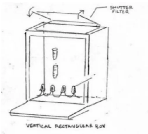
Figure 18. Illuminator Concept 5 Sketch. ... 14
Figure 19. Illuminator Concept 6 Sketch. ... 14
Figure 20. Illuminator Concept 7 Sketch. ... 14
Figure 21. Folded Box Illuminator, Folded and Slightly Unfolded Isometric Views. ... 15
Figure 22. Folded Box Illuminator, Unfolded Front and Isometric Views. ... 16
Figure 23. Matchbox Illuminator, Front and Isometric View. ... 16
Figure 24. Matchbox Illuminator, Outer Sheath Folded and Unfolded Views. ... 16
Figure 25. Matchbox Illuminator, Inner Box Folded and Unfolded Isometric Views. ... 17
Figure 26. Folded Box Illuminator Concept Prototype with Tab Folds... 17
Figure 27. Matchbox Illuminator Concept Prototype with Battery Cutout. ... 18
Figure 28. CDR Final Illuminator Design. ... 19
Figure 29. CDR Sheath, Folded and Unfolded Views. ... 20
Figure 30. CDR Box, Folded and Unfolded Views. ... 20
Figure 31. CDR Sheath Template. ... 21
Figure 32. CDR Box Template. ... 21
Figure 33. CDR Illuminator Electrical Circuit Diagram. ... 21
Figure 34. Inner Layout of Electrical System. ... 22
Figure 35. Test Tube Rack. ... 23
Figure 36. Lighting Rack. ... 23
Figure 37. Test Tube Templates for Two Sizes. ... 23
Figure 38. New Illuminator Final Design Full Assembly. ... 24
Figure 39. Final Sheath Design. ... 24
Figure 40. Final Box Design. ... 25
Figure 41. Large Test Tube Stand (2.0 mL). ... 26
Figure 42. Small Test Tube Stand (0.6 mL). ... 26
Figure 43. Final Electric Circuit Diagram. ... 27
vi
LIST OF TABLES
Table 1. Engineering Specifications and Requirements. ... 9
Table 2. Illuminator Full Concepts and Functions. ... 13
Table 3. Number of Illuminators Available with Purchase of Materials. ... 31
1
1.
INTRODUCTION
Dr. Javin Oza, a professor in the biochemistry and chemistry department at California Polytechnic State University, San Luis Obispo presented the problem of an accessible and portable ultraviolet illuminator for biological research and discovery. In the field of synthetic biology, researchers use ultraviolet illuminators in their laboratories to view the glowing output signal from fluorescently-dyed biomaterials like DNA samples after a reaction has taken place. However, many commercially available ultraviolet illuminators are usually very expensive, are not portable for field uses, or are not accessible to the general public. Our team, comprised of three mechanical engineering students, has a project goal to design and build a portable ultraviolet fluorescence device that meets our sponsor’s requirements and improves accessibility to quality scientific equipment. This document describes the initial background research for the project and establishes project objectives. It presents the concept ideation process resulting in the concept design of the device; it also describes the final design of the illuminator, its features, and total cost of materials. It describes how the illuminator is assembled and the engineering tests that will verify the device meets Dr. Oza’s specifications. Lastly, the document defines the plans for project implementation from start to completion, showing the effective project timeline.
2.
BACKGROUND
In order to form our understanding of the scope of the project, our initial background research consisted of three separate categories: sponsor/user interviews, technical literature, and product research. We conducted sponsor and end-user interviews to distinguish the specific customer requirements for the project. The technical literature found regarded future applications and industry standards involving our project. Our product research focused on finding competitive current products and relevant patents that indicate key features and technology that would potentially be useful to our project.
2.1 Sponsor/End-User Interviews
Sponsor Interview
We interviewed our sponsor, Dr. Oza, to understand his vision, requirements, and goals for the outcome of the project as well as obtain background on the biological processes and testing that require UV fluorescence illuminators. At the initial meeting, he clarified that his main goal is to “increase access [to scientific discovery], and decrease cost,” (Oza) emphasizing the importance of accessibility in our project’s outcome. The necessary design components for the UV transilluminator and Dr. Oza’s specific requirements for our project are:
Necessary Design Components
• UV lighting system
• Incorporated electrical system to power lighting system
• Heating element to speed up reaction times and produce 20˚C change in temperature
2 Needs/Wants
• Able to quantify different levels of glow with the ImageJ application
• Portable, able to be carried in one hand
• Small form factor
• Low production cost
• Manufactured with biodegradable/sustainable material, easily disposable
• Accessible to many people, increases accessibility to scientific fieldwork
• Able to be assembled/disassembled quickly
• Collapsible
• Utilizes different visible light-filtering screens to view glow
Our group determined that some desired, but not required goals mentioned by the sponsor at the initial meeting may not be in the direct scope of our project. However, the goal of making the illuminator a commercialized product could be carried out by future senior project teams.
End-User/Student Interviews
Our group also interviewed a few of Dr. Oza’s student lab assistants, Logan Burrington, Philip Smith, Nicole Gregorio, Max Levine, and Byungcheol So. Each could be a potential end user of the final product. Their needs and wants as customers have dual function: as lab researchers, they would benefit from a portable transilluminator device to assist them in work. As college students in STEM majors, they would benefit from access to a cheap transilluminator that would enable them to easily conduct scientific experiments.
Like Dr. Oza, the students identified portability and a small form factor as very important requirements for the illuminator to have. Also, to increase the fluorescent light output, the lab assistants desired an increased surface area to volume ratio of the device. They believed that durability, the ability to use multiple filters, and an adaptor to fit different sized tubes would also be beneficial features for the illuminator (Burrington, et al.).
2.2 Technical Research Illuminator Applications
There is an abundance of useful applications for a portable UV fluorescence illuminator in the fields of biology research and development. The transilluminator is mainly used as a fluorescence detection device for the glowing signal output of biomaterials. The need for an illuminator is high, especially for a product that is of low cost and easily accessible to many.
3
Figure 1. iVAX Vaccine Synthesis Process Diagram. (Stark, et al.)
Another field of biology that incorporates the need for a portable fluorescence device is the field of bacteria detection. The development of a portable microfluidic polymerase chain reaction (PCR) device by researchers at Teesside University in the United Kingdom utilized a microfluidic PCR chip that slid between three different temperature zones to activate a fluorescent glow output (Salman, et al.). PCR is a process by which multiple copies of a segment of DNA can be made. The main application for this portable device would be to rapidly identify infectious bacteria for medical purposes.
Movements toward low-cost fluorescence detection systems are being attempted by using dye-type DNA-staining reagents. In one study, the researchers’ DNA detection system cost less than $100 in hardware and the fluorescent output was tested with cyan LEDs and black light (Motohashi). The black light system accomplished greater detection of DNA fragments when compared to a commercially used UV transilluminator.
UV transilluminators also are involved in classroom applications. A college biochemistry class at Bandung Institute of Technology in Indonesia used UV transilluminators in a lab exercise involving enzyme preparations to view indication of fibrinolytic activity (Nurachman, et al.). Fibrinolysis is a bodily process that prevents blood clots from forming. The transilluminators detected the glow from fluorescent dye and indicated a complete reaction.
Finally, a global movement, dubbed “DIYbio” (do-it-yourself biology), involves a community of people pursuing “biology outside of scientific institutions by amateurs, students, [and] ‘hobbyists’” (Landrain, et al.). The DIYbio community tries to make an impact on global health issues in the fields of modern molecular biology and synthetic biology by conducting research in laboratories that are not institution affiliated. They support opening access to state-of-the-art biology equipment for amateur scientists. While our group does not recognize or deny the validity of the DIYbio community’s practice, we believe that their mission to improve the general public’s access to scientific equipment and testing is a goal we would like to achieve with our project and the portable fluorescence UV illuminator.
Government Standards
4
According to a UV transilluminator radiation exposure study by Farhang Akbar-Khanzadeh and Mahdi Jahangir-Blourchian, UV transilluminators expose operators working in proximity to the transilluminator to UV radiation. This radiation may be in excess to exposure regulations, and this overexposure occurs even though the operator is only exposed to the UV radiation for short amounts of time. Guidelines recommend that users should have appropriate shielding and protective equipment when working with transilluminators.
2.3 Product Research
The product research conducted indicates existing products with potential features that we may incorporate into our design, as well as their level of portability and accessibility to the general public.
The main competition to our project is the miniPCR P51 Molecular Fluorescent Viewer, shown in Figure 2a. The P51 has an all-in-one molecular visualization system and DIY assembly, allowing students to easily conduct various fluorescence-viewing “Learning Labs” also made by miniPCR (miniPCR). The P51incorporates the necessary fluorescent illuminator components: UV lighting, an integrated power source, a filter to view the fluorescence through, and ability to hold standard test vials. Its outer material, cardboard, is also recyclable. However, its assembled form is portable but not easily carried in one hand, as seen in Figure 2b; the product also does not seem easily collapsible after assembly. The P51 is too large to be easily carried and stored in field applications, but it is widely accessible to students at a price of $28.
Figure 2a. miniPCR P51 Molecular Fluorescent Viewer. (miniPCR)
Figure 2b. miniPCR P51 with Fluorescent Glow. (miniPCR)
Portable Devices
5
Figure 3. Northwestern 3D-Printed UV Transilluminator. (Alam, et al.)
Amplino, shown in Figure 4, is a low cost, portable PCR (polymerase chain reaction) device that allows users to detect small quantities of DNA in samples (Nordling). It is able to complete diagnostic testing in order to detect environmental hazards, crop-threatening organisms, animal pathogens, and parasites and viruses (Amplino). Although it is portable and effective in function, it is not an available product to buy and still too large to be easily collapsed or held in one hand. No information on Amplino has been updated since 2015.
Figure 4. Amplino Portable PCR Device. (Amplino)
6
Figure 5. Crystal Technologies Handheld UV Lamp. (Thomas Scientific) Benchtop Devices
The Accuris E3000 UV Transilluminator in Figure 6 is a benchtop device that allows for the fluorescent detection of DNA samples and outputs ultraviolet (UV) light at a midrange of 302 nanometers (Transilluminators.com). It incorporates an acrylic cover to view the UV light safely and two UV intensity settings. The device has a compact design for a benchtop unit, but it cannot be handheld or portable due to its requirement of a plug-in power source. This device costs a little less than $1,000, making it a viable instrument for classroom lab use but not for general purpose uses.
Figure 6. Accuris E3000 UV Transilluminator. (Transilluminators.com)
The BioTek Cytation 5 Cell Imaging Multi-Mode Reader shown in Figure 7 conducts quantitative data collection and imaging of samples in slides, Petri dishes, flasks, or 6- to 384- well microplates (Fisher Scientific). Dr. Oza’s lab at Cal Poly uses this device for their research and development. The device outputs the results to a connected software program for real-time data tracking. However, it is a benchtop unit that requires a plug-in power source, affecting its portability. The high level of necessary scientific knowledge to use this device and quantify the resulting data makes it inaccessible to the general public and most non-scientific professionals. It is extremely expensive at over $61,000.
7 Other Products
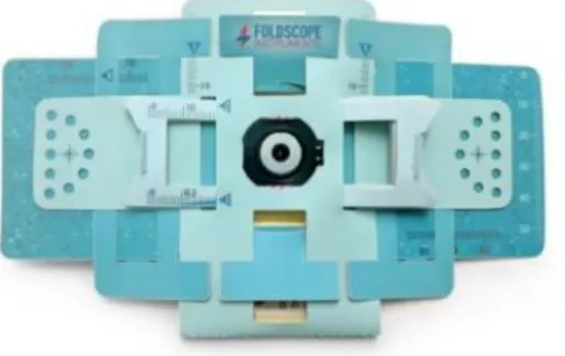
The accessibility to scientific equipment and portability needs specified by our sponsor are directly related to the needs answered by the invention of the Foldscope shown in Figure 8, a mostly paper microscope that utilizes principles of origami in its form. Like a typical microscope, it has magnification capabilities up to 140 times and a resolution 2 microns (Foldscope Instruments). The cost of its parts should total to less than $1, and nearly half a million Foldscopes have been disseminated around the world.
Figure 8. Foldscope. (Foldscope Instruments)
Relevant Patents
The relevant patents regarding ultraviolet transilluminators and ultraviolet lighting devices are in Appendix A. A table consisting of each patent number, patent description, and image (if available) identify the key features and purpose of each product. Keywords used in Google Patent search to find these products consisted of “portable UV illuminator” and “UV transilluminator.”
3.
OBJECTIVES
The requirements set forth by our sponsor defined the challenge of the portable fluorescent illuminator and the scope of the project. From these requirements, our team created a boundary diagram depicting the project’s scope and the aspects of existing illuminators we seek to improve. Furthermore, Quality Function Deployment (QFD) was performed to determine the most important specifications to our sponsor and the engineering tests and tolerances to meet each specification.
3.1 Problem Definition
8 3.2 Boundary Diagram
The boundary diagram in Figure 9 illustrates the scope our team has set for the project and demonstrates the specific goals we would like to achieve. The boundary is drawn around items that our team has control of in the project; everything outside the boundary is an uncontrollable variable. The portable illuminator is drawn clear to show the internal components.
Figure 9. Illuminator Boundary Diagram.
The user should be able to carry the device in one hand for it to be portable, which is why the boundary is drawn around the outer form of the transilluminator. Our team will also be able to control the material the device is made of. The inner components, such as the ultraviolet lighting, test vials, power source, heating element, and electrical wiring are all under our control to choose and position within the device. The intensity of the fluorescent output seen by the user can be controlled through the filter types and UV light source positioning within the device.
The variables that our team does not have control over include the user and the chemical reactions occurring inside the test vials. The user is shown outside the boundary because the product should be designed to be used by a variety of people, and the user is key in viewing fluorescent output. Although our project is integrated with the science involving the fluorescent output signals of biomaterials, the types of chemicals placed in the vials and improvement of chemical reaction times are not within our scope. 3.3 Quality Function Deployment
In the QFD (Quality Function Deployment), we listed our customer requirements and the engineering requirements that will be tested in our final design. QFD exists to analyze the customer’s needs and compare them with engineering specifications and tests. This ensures maximum customer satisfaction with the final product, and it develops an understanding of the most important customer needs and engineering specifications for the product. The full QFD, in its “House of Quality,” can be found in Appendix B.
9
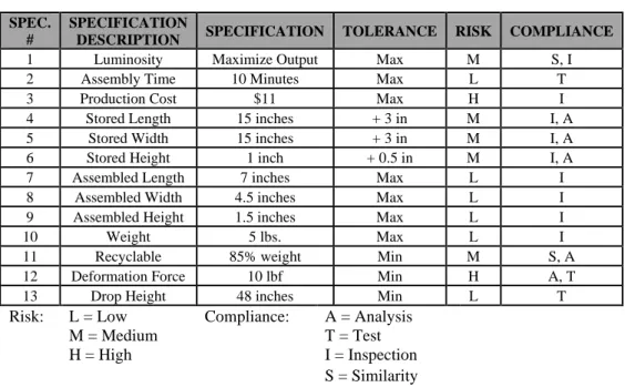
Table 1 displays a list of the specifications and the targets for this project determined from the QFD, ranked in order of importance. Each of the specifications shown above have a target assigned to them that we will strive to meet with our final design. Each specification has a tolerance, risk, and compliance associated with them. The tolerance is the range of deviation from the nominal target deemed acceptable in the final design. The associated risk is the evaluation of how difficult it will be to meet these targets. Finally, compliance is the types of evaluation our team will be doing to ensure each specification’s target requirement has been met and is within the tolerance range we defined.
Table 1. Engineering Specifications and Requirements.
SPEC. #
SPECIFICATION
DESCRIPTION SPECIFICATION TOLERANCE RISK COMPLIANCE 1 Luminosity Maximize Output Max M S, I 2 Assembly Time 10 Minutes Max L T
3 Production Cost $11 Max H I
4 Stored Length 15 inches + 3 in M I, A 5 Stored Width 15 inches + 3 in M I, A 6 Stored Height 1 inch + 0.5 in M I, A 7 Assembled Length 7 inches Max L I 8 Assembled Width 4.5 inches Max L I 9 Assembled Height 1.5 inches Max L I
10 Weight 5 lbs. Max L I
11 Recyclable 85% weight Min M S, A 12 Deformation Force 10 lbf Min H A, T 13 Drop Height 48 inches Min L T
Risk: L = Low Compliance: A = Analysis M = Medium T = Test H = High I = Inspection
S = Similarity
Each specification is explained in further detail:
1. Luminosity is a complicated specification since Dr. Oza did not know what exact level of luminosity, or glow, he desired. It is also a factor that will affect cost drastically since UV lights of higher luminosity will inevitably cost more. Dr. Oza desires a luminosity level that can achieve the best fluorescence output from the biological samples. For our project, no personal protective equipment (PPE) should be needed to protect the user from UV radiation. The UV light filters and the outer enclosure will protect the user from radiation exposure. 2. The ease of use, or usability, and accessibility were some of our client’s requirements. For the
device to be easy to use, the device must be assembled and be ready for use within 10 minutes maximum.
3. Cost is another major driving factor for this design. Since the device should be accessible to everyone, including students at Cal Poly, it should cost no more than $10.
4 - 6. Stored dimensions affect the portability of the device. Dr. Oza desired the device to have a small form factor when disassembled for storage to insure portability.
10
10. Since portability is a major requirement of this project, the device should be as light as possible. In this case, a weight of 5 lbs. is an acceptable target to satisfy the portability requirement.
11. Our client would like the device to be comprised of disposable/recyclable material. The set target is 85% weight recyclability. The electrical components such as the UV LEDs, batteries, and wiring will not be recyclable.
12 -13. Drop height and stiffness/deformation are strength and rigidity requirements that our team deemed necessary after our research and consideration as to how this device will be used. The device will be handled by students, used in the field where it will be exposed to the elements, and exposed to loads or shocks if dropped or carried in a backpack. This specification to ensures the durability requirement of our client is met.
The high-risk specifications of our project are production cost and deformation force. These are both related to the components and materials used to manufacture the device. The production cost depends greatly on the types of LEDs, outer casing material, and electrical hardware we choose to use in our product. The production cost is also tied into our most important specification, luminosity; with better quality ultraviolet LEDs, the price may be greater. Also, since the product is to be made of a lightweight and recyclable material, the device may not be able to withstand 10 lbs. of force. The product’s structural integrity may fail at lower weights and not meet the specification.
4.
CONCEPT DESIGN
The concept ideation process consisted of performing functional decomposition, creating function prototypes, and evaluating different functions in Pugh and weighted decision matrices in order to develop the final concept design of the portable fluorescence transilluminator. The final concept has two variations, folded box and matchbox, that will be tested with users to understand the best configuration for simple assembly and ease of use. The folded box configuration is shown in Figure 10 and the matchbox configuration is shown in Figure 11.
Figure 10. Folded Box Illuminator Concept. Figure 11. Matchbox Illuminator Concept.
4.1 Concept Development/Ideation and Function Concept Prototypes
11
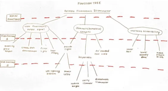
a function is necessary, and descending down from the top of the function tree branches explains “how” a function will be achieved. The function tree for the portable fluorescent illuminator in Figure 12 outlines the three major functions for the illuminator device: it must allow the viewing of a fluorescent glow, illuminate biological samples, and increase accessibility. Each sub-function underneath defines a more specific method to achieve the main function.
Figure 12. Functional Decomposition Function Tree.
The various ideas generated to achieve each of the sub-functions, compiled in Appendix C, were produced without regard to feasibility, practicality, or number of ideas. The team freely wrote the ideas on sticky notes and placed the note under the specific sub-function written on a board during the functional decomposition process. The main goal was to have at least five or more ideas for each sub-function and at least 150 or more ideas in total.
The team also used brainsketching to design new concept ideas. For five minutes, each member drew a sketch in his/her logbook of an envisioned prototype and added desired features. After, our team switched logbooks and continued to add features on another member’s sketch for another five minutes. This was done a third time to make sure all members had an opportunity to sketch on others’ ideas. The sketches from the brainsketching exercise in Appendix C display new concepts not considered in functional decomposition. These concepts include a cylindrical illuminator shape, finger holders for a small illuminator, LED light strips positioned in a circle, a heating element achieved with hot pack heating beads, and an accordion-folded illuminator held up by outer flaps.
Our team developed function prototypes mainly from cardboard, tape, and plastic test vials to model a few of the function concepts generated during the functional decomposition and ideation processes, shown in Appendix D. These models allowed the team to visualize how certain ideas would work and indicated which functions would be easy or difficult to manufacture in the future.
4.2 Pugh, Morphological, and Weighted Decision Matrices
12 4.2.1 Pugh Matrices
A Pugh matrix compares the different ideas for a specific function using a set of criteria. One idea is used as the “datum” to compare every other idea to. The datum is assumed to best meet the criteria and have a resulting score of 0. The values of +, -, or S are assigned to an idea corresponding to whether it is better, worse, or the same, respectively, as the datum in meeting the criteria specified. The amount of +, -, and S are added up for each idea to determine how well the other ideas match the criteria with respect to the datum. A negative score indicates that the idea does not meet the criteria as well as the datum, a positive score indicates that the idea meets the criteria better than the datum, and a score of zero means that the idea meets the criteria on the same level as the datum.
Each of the five Pugh matrices in Appendix E were developed for one of the illuminator’s functions: shape, ultraviolet lighting system, test tube orientation, filter holder, and collapsible form. As expected, the datum ideas in each Pugh matrix were the best amongst the others; these ideas were the most likely to be included in the final design concept.
4.2.2 Morphological Matrix and Concept Sketches
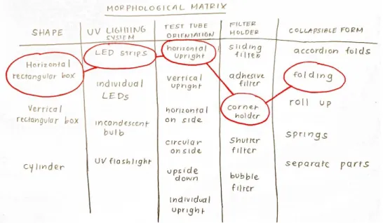
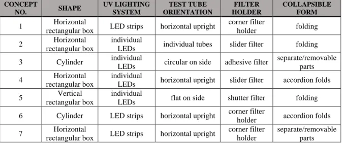
The morphological matrix shown in Figure 13 displays the various ideas for each aspect or function of the illuminator. Full concepts for the illuminator were generated from the matrix by choosing one idea in each column. For example, one full concept that our team generated was a horizontal box shape with an LED strip lighting system, horizontal and upright oriented test tubes, a corner holder for the filter, and a folding method to collapse the device.
Figure 13. Morphological Matrix.
13
Table 2. Illuminator Full Concepts and Functions. CONCEPT
NO. SHAPE
UV LIGHTING SYSTEM TEST TUBE ORIENTATION FILTER HOLDER COLLAPSIBLE FORM
1 Horizontal
rectangular box LED strips horizontal upright
corner filter
holder folding 2 Horizontal
rectangular box
individual
LEDs individual tubes slider filter folding 3 Cylinder individual
LEDs circular on side adhesive filter
separate/removable parts 4 Horizontal
rectangular box
individual
LEDs horizontal upright slider filter accordion folds 5 Vertical
rectangular box
individual
LEDs flat on side shutter filter folding 6 Cylinder LED strips horizontal upright corner filter
holder accordion folds 7 Horizontal
rectangular box LED strips horizontal upright
corner filter holder
separate/removable parts
Figure 14. Illuminator Concept 1 Sketch. Figure 15. Illuminator Concept 2 Sketch.
14
Figure 18. Illuminator Concept 5 Sketch. Figure 19. Illuminator Concept 6 Sketch.
Figure 20. Illuminator Concept 7 Sketch.
A box shape was present in five of the seven concepts because it is an uncomplicated shape to manufacture and assemble. The concepts all incorporated either ultraviolet LED strips or individual LEDs because they would be the easiest to incorporate with a compact electrical system. The collapsible form included some type of folding or separate/removable parts, which may be the quickest form of disassembly. Orienting the test tubes in a horizontal, upright fashion was featured in most of our concepts because it would be the simplest orientation to ensure the samples stay at the bottom of the test tube and that the ultraviolet light hits the samples. The test tubes would also be easiest to install into or remove from the device. Various filter ideas were incorporated into the concepts; the idea used most frequently was the corner filter holder. Some unpopular ideas included the “bubble” filter, upside down and vertical test tubes, and a flashlight UV system, most likely due to foreseeable assembly or manufacturing issues.
4.2.3 Weighted Decision Matrix
15
The best concept, determined by the highest score from the weighted matrix, was Concept 1 due to its high rankings with the major specifications of portability, UV lighting, usability, and a small form factor. The second and third best concepts were Concept 7 and Concept 5, respectively, which also ranked high on the major specifications of portability and usability. Concepts 3 and 6 were amongst the lowest-ranked concepts due to the difficult cylindrical shape to manufacture and assemble out of cardboard.
The only difference between Concepts 1 and 7, the top two concepts, were the differences in collapsible form. Otherwise, they both included LED strips, upright, horizontally oriented test tubes, and a corner filter holder. A device with only one main part to assemble or disassemble like Concept 1 would be easier to manufacture and store compared to a device with separate parts like Concept 7, which is why Concept 1 ranked higher.
Instead of one final design for the illuminator, our team determined that it was best to have two concept configurations based on Concepts 1 and 7. The concepts are similar, and it would be beneficial to receive user feedback on the assembly time, ease of use, and portability aspects of each design. This feedback would help distinguish the better configuration and any design modifications that need to be made. 4.3 Concept Design
The final design concept’s two variations each feature the same general design for the lighting system and light filter orientation; each also uses the main shape of a horizontal, rectangular box. Both incorporate ultraviolet LED light strips and have the light filter held by its corners in a cut out slit.
The simplest variation of the illuminator, the folded box, shown in different configurations in Figures 21 and 22, is folded from a single piece of material. It utilizes tabs that can be entered into slits or tucked behind flaps to hold the illuminator’s shape. The front of the illuminator contains a cutout for the filter and folds over the location of the test vials.
(a) Folded (b) Slightly Unfolded
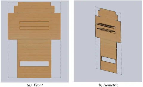
16
(a) Front (b) Isometric Figure 22. Folded Box Illuminator, Unfolded Front and Isometric Views.
The second variation of the illuminator, shown in Figures 23-25, has a matchbox form with an outer case holding the filter that slides over an open-faced box containing the test vials and electrical components. Both variations are folded because it is an easy assembly method for users and a simple way to avoid using fasteners or large amounts of glue.
(a) Front (b) Isometric
Figure 23. Matchbox Illuminator, Front and Isometric View.
(a) Folded (b) Unfolded
17
(a) Folded (b) Unfolded
Figure 25. Matchbox Illuminator, Inner Box Folded and Unfolded Isometric Views.
Each design, which will be manufactured out of thin cardboard or some paper-based product, has small slits around the viewing window to hold the ultraviolet light filter. The test vials will be lined up in front of the viewing window in a horizontal, upright fashion, held in place by a horizontal flap protruding from the back edge with holes cut out to nest the test tubes in. Underneath the test tubes, the ultraviolet LED light strip will be adhesively attached on another horizontal flap to light the bottom of the samples. Finally, the battery to power the light strip will be secured in a cutout that utilizes negative space at the bottom of the illuminator.
The concept prototypes manufactured out of chipboard and kraft paper depict the physical representations of the illuminators along with the approximate proportions. The folded box illuminator in Figure 26 depicts the folding method with various tabs to hold the illuminator’s shape. The matchbox illuminator in Figure 27 demonstrates the “negative space” battery holder using a cutout strip. Some elements not included in both prototypes are the corner filter holder, the light filter, the test tubes, and the electrical components for the device.
18
Figure 27. Matchbox Illuminator Concept Prototype with Battery Cutout.
The size of each illuminator is no longer than 6 inches in length, 5 inches in width, and 2 inches in height. The goal is for the device to be handheld by students and adults, so it is key to eventually minimize the size of the device. The electrical components will fit inside the outer casing and be attached with some form of adhesive to the bottom of the illuminator. The holes or cutouts to hold the test tubes will accommodate the standard sizes and fit the tubes snugly. The user should be able to place the test tubes and electrical components in the appropriate locations before folding up the illuminator into its assembled form; the user should also be able to remove the components after collapsing the illuminator.
Some undetermined parts of the final illuminator concept are the positioning of the ultraviolet lights, electrical systems, and heating element to obtain the best fluorescent output. The positioning of the lights will greatly affect how the user views the output, and the heating element is necessary for the chemical reaction and fluorescent glow to occur. Furthermore, the type of heating element is still undetermined. Our team has considered using heating coils or even the activation particles from hand warmers, but more material research must be conducted to determine a feasible method to heat the samples.
4.4 Preliminary Design Risks
Prior to any actual testing or manufacturing, our team considered the risks involved in creating the portable fluorescence illuminator. The Design Hazard Checklist in Appendix G indicates that utilizing a battery as a power source, ultraviolet radiation, and potential unsafe use would be main hazards involved in creating the illuminator. The light filters covering the viewing windows should filter out the ultraviolet radiation and protect the user, but safety precautions in the event of unintended use should be considered. As a safety measure in the design of our device, the ultraviolet lighting could remain off until the illuminator case is fully closed to contain the UV lighting, triggering a button of some sort to turn on the lights. This could also be incorporated for the heating element, so the heating element is not active when the device is disassembled or test tubes are not in the device.
19
5.
FINAL DESIGN
The final design of the portable fluorescence illuminator was developed out of the concept design for the matchbox configuration. The final design consists of three main components: the sheath, the box, and the electrical circuit. After the Critical Design Review, our team made modifications to the illuminator design to simplify the assembly and manufacturing processes. Through some preliminary analysis, our team determined that the design meets Dr. Oza’s specifications for size, cost, and recyclability. Most importantly, the design contains components such as a heater and ultraviolet LED lights that allow it to operate as a functional illuminator. Furthermore, our team considered the safety, maintenance, and repair of the device, as well as the various failure modes associated with our design in a Failure Modes and Effects Analysis (FMEA). An indented bill of materials (iBOM) provides the cost and source of each individual part needed to make the device as well as the total cost to create one illuminator.
5.1 CDR Proposed Final Illuminator Design
The design described in the following section is the initial final design conceived by the team at the Critical Design Review (CDR). However, due to changes in the LED light type post-CDR, many of the illuminator’s design features such as size, electrical circuit, and filter placement could be simplified. These design changes will be further explained in a later section.
The illuminator’s final design is in the matchbox configuration. It contains three main subassemblies: the sheath, the box, and the electrical circuit. While the electrical circuit and test samples are placed in the box, the sheath slides over and around the box to view the fluorescent glow. The matchbox configuration was chosen over the folded box configuration because it better met our sponsor’s criteria for size, reusability, and safety measures. The illuminator’s final design, shown in Figure 28, is slightly modified from the concept design with a slightly different shape for the sheath and box, as well as a different test tube rack design. Furthermore, the design also incorporates an electrical circuit consisting of a battery, an ultraviolet UV LED strip, a limit switch, and an adhesive heating strip that fits inside of the recyclable housing. The circuit will be used to heat and illuminate the biological samples while controlling when the UV light can be on.
20 5.1.1 Sheath and Box
As shown in Figure 29, the sheath of the illuminator is similar to the concept design; however, the side flap has been removed. The folded dimensions of the sheath are 5.2” × 5.2” × 1.75” in length, width, and height, respectively. There is a 3.6” × 1” window cutout in the front for the acrylic light filter, which will be attached with adhesive double-sided tape. Furthermore, there is a small slot cut out on the back of the sheath for the battery switch to be accessible to the user while the illuminator is in use.
(a) Folded (b) Unfolded
Figure 29. CDR Sheath, Folded and Unfolded Views.
The box, shown in Figure 30, is an open-faced box, similar to the concept design. However, the flattened layout is slightly modified to add more flaps on each side so the box can hold its shape well when assembled. When folded, the horizontal tabs on the upper and lower panel help the lengthwise walls stay upright when tucked under the flaps for the walls on the left and right. The vertical walls of the box also have a thickness of 0.18”, making the sides more robust and the overall design more secure. When folded, the dimensions of the box are 5” × 5” × 1.5” in length, width, and height, respectively, creating some clearance with the sheath. Similar to the sheath, it contains a 0.5” square slot cut on the center panel for the battery switch.
(a) Folded (b) Unfolded
21
Both sheath and box are meant to be assembled by the user. The sheath can be cut out of cardboard or some other rigid paper-based material, while the box can be made out of cardstock or kraft paper for easy folding and a robust shape. Two 2-D templates, complete with lines for cutting and folding, were created for both parts; the templates are shown in Figures 31 and 32. The letters on the figure correspond to the different panels and flaps on each piece, the dotted lines represent cutting lines, and the red lines denote folding lines. The templates can be printed on 11” × 17” pieces of paper or traced onto cardboard and used to make the device.
Figure 31. CDR Sheath Template. Figure 32. CDR Box Template.
5.1.2 Electrical Circuit and Removable Panel
The electrical circuit is one of the most critical components of the overall design. It incorporates a 9-volt battery, an adhesive polyimide heater, an ultraviolet LED light strip, and two limit switches. The circuit diagram is shown in Figure 33.
Figure 33. CDR Illuminator Electrical Circuit Diagram.
22
biological samples. The heater, placed directly below the test tubes, heats the samples with a change in temperature of 20˚C to speed up the initial reaction that produces the fluorescent glow. The two limit switches placed at the bottom of the box act as safety precautions so the LED lights do not turn on when the box is not in the sheath. Both switches must be engaged and the battery switch must be set to “on” before the LED lights will turn on.
Figure 34. Inner Layout of Electrical System.
All of the electric circuit components in the circuit are attached by adhesive strips or double-sided tape to a cardboard panel that can be placed directly inside the box and removed when necessary. This is done so the electrical circuit can be modular; if the sheath or box become damaged, the electrical circuit can be removed and reused in a new illuminator. This improves the recyclability of the entire device. The removable panel also has a slot cut out for the battery switch, and the battery holder is positioned over this slot with the switch.
The racks to hold the test tubes and the LED strip, shown in Figures 35 and 36, are also attached to the removable panel. The test tube rack is positioned above the light strip rack, and the heater is positioned between the two. The racks are made out of paper that is cut in a 4.1” × 1.3” rectangle and folded at a 90˚ angle. The LED strips have an adhesive backing, which will be stuck directly on the lighting rack.
Box Removable
Panel
Test Tube Rack
Test Tube Template
UV LED Strip Light Rack
Limit
23
Figure 35. Test Tube Rack. Figure 36. Lighting Rack.
The test tube rack has a 3.5” × 0.5” rectangular slot cut out so the test tubes can be nestled in after being inserted into a test tube template. The two test tube templates, shown in Figure 37 are made out of paper cut into 4.1” × 0.75” rectangles with a pattern of holes to hold test tube sizes of 0.6 mL and 2 mL. The templates rest on top of the racks as the bottoms of the test tubes sit in the rectangular slot cut out of the rack.
a) 0.6 mL Test Tube Template b) 2 mL Test Tube Template
Figure 37. Test Tube Templates for Two Sizes. 5.2 Post-CDR Final Design Modifications
24
Figure 38. New Illuminator Final Design Full Assembly. 5.2.1 Sheath and Box Modifications
The sheath modifications consisted of consolidating the sheath’s dimensions, adding the filter holder mechanism, and including self-locking tabs for the sheath to hold its shape. The modified dimensions of the sheath are 4.55” × 4.12” × 1.14”, a reduction of 25.95 in3 from the previous design.
The sheath’s unfolded and folded isometric views in Figure 39 display the filter holder mechanism and the self-locking tabs. These were both implemented in order to reduce the use of adhesives like tape, glue, or Velcro dots to form the sheath. To assemble the sheath using the self-locking tabs, the sheath is folded at the designated lines, and the tabs on the top are inserted into the slits cut out at the bottom.
(a) Folded (b) Unfolded
Figure 39. Final Sheath Design. Box
Test Tube
Light Filter
Blue LED Strip
Test Tube Stand
Light Filter Holder
25
The filter holder mechanism added onto the sheath acts as a pocket for the acrylic panel to be inserted in. A tab on the right inserts into the flaps folded down at the top and bottom to form the pocket, and the acrylic filter sits between the front of the filter holder mechanism and the front of the sheath’s viewing window. Thus, the filter can be inserted and removed without using any adhesive attachments and effectively filters out the light to view the fluorescent glow. The filter was changed from amber (orange) acrylic to yellow acrylic due to better viewing of the fluorescence with the yellow filter.
The box modifications consisted of reducing the box’s dimensions, simplifying the box’s flat pattern, and including tabs to hold the walls of the box up when assembled. The box’s dimensions are reduced to 4.5” × 4” × 1”, which is a change of 19.5 in3 from the previous design. This change occurred because the box did not need to be as thick or wide to accommodate all of the necessary components.
The box’s flat pattern, shown in Figure 40, has less folds and complex tabs than the previous design; the folded view is also shown in Figure 40. The previous design took a long time to assemble and was not intuitive to users, requiring more complicated instructions.
(a) Folded (b) Unfolded
Figure 40. Final Box Design.
The new flat pattern has tabs along the on each of the four panels that form the sides of the box that insert into slits cut on the main, center panel of the box. These tabs help keep the walls of the box upright and also give the box’s walls a double layer of material for added strength. The panels along the width of the box have tabs sticking out to the side that fold under the panels along the length of the box to stabilize the side walls.
Both sheath and box still have a cut-out squares on the back in order to make the on/off power switch accessible to the user. The battery pack still sits at the bottom of the box and is attached using Velcro dots.
5.2.2 Test Tube Stand Modifications
26
onto the top of the battery pack and positioned directly under the test tube stands to provide light to the samples. The test tube stands still have two different versions; one to accommodate 2.0 mL tubes and another to accommodate 0.6 mL tubes. The unfolded and folded views of both stands are shown in Figures 41 and 42.
The length and width for both test tube stands are 8 inches and 4.3 inches, respectively. The test tube stand for the 0.6 mL tubes has a height of 1.3 inches and a pattern of 9 holes for the tubes. The test tube stand for the 2 mL tubes has a height of 1.9 inches and a pattern of 5 holes for the tubes.
The stands are folded from their flat pattern into a small box that locks with tabs that insert into slits at the bottom. It also has a viewing window, similar to the sheath. The holes for the test tubes are located on the top face of the box, while the viewing window is located on the front face. Another smaller window is at the bottom of the box, where the LED light can shine through to hit the samples. When the test tubes are placed in the stand, the bottom of the tubes (where the samples are) can be viewed by the user through the viewing window.
(a) Folded (b) Unfolded
Figure 41. Large Test Tube Stand (2.0 mL).
(a) Folded (b) Unfolded
27 5.2.3 Electrical Circuit Modifications
The electrical circuit was simplified due to the discovery that UV LED lights were not sufficient enough to produce the fluorescent glow; its appropriate wavelength was too high. After some preliminary tests, our team found that blue LED lights were able to excite the necessary fluorescent glow and had a nominal wavelength closer to the excitation wavelength for the samples. Since blue LED lights can be used, there is no risk of UV radiation exposure. This eliminates the need for limit switches to make sure the LEDs would not be on when the box is in the sheath.
Another circuit modification included making the lighting and heating systems independent of each other. Our team determined that the actions of lighting and heating did not need to occur at the same time and be part of the same circuit. A USB heater was substituted for the polyimide heater, so the heating action could be performed independently by plugging the heating element into a computer USB port or wall outlet. Also, the heating element was moved from inside the box to the sheath, on the panel opposite of the filter. Therefore, in order to heat samples, the sheath can be slid with the heater side over the box opening so the heater faces the samples.
The resulting electric circuit for the lighting system only consists of the 9V battery and a 3-inch blue LED strip. A switch on the 9V battery holder cuts off the flow of current from to the LEDs. The heater, as mentioned previously, forms its own independent circuit with the power source that the USB plugs into. The lighting circuit is shown in Figure 43.
Figure 43. Final Electric Circuit Diagram.
5.3 Alignment with Sponsor Requirements
Dr. Oza’s main specifications for the illuminator regarded portability, accessibility, and recyclability. The design of the device had to be collapsible, easily disposable, and in a small form factor. The cost of the device had to be around $10 and less than other existing products. Another specification included incorporating a heating element in the device to speed up the chemical reaction in the tested samples. Most importantly, to function as an illuminator, the device also had to provide ultraviolet lighting at the correct wavelength to excite the fluorescent glow of the test vials.
The size of the illuminator has a direct correlation with its portability. In order to meet Dr. Oza’s specifications, the illuminator must be within dimensions of 15” × 15” when stored (flattened) and 7” ×
28
4.5” × 1.5” when assembled. The flattened pattern of the sheath and box are within the projected dimensions, as are the folded dimensions of the sheath, the outermost component. The flat pattern of the sheath has maximum dimensions of 11.35” × 9.85”, and the flat pattern of the box has maximum dimensions of 8.45” × 7.95”. The assembled dimensions of the sheath are 4.55” × 4.12” × 1.14”, well within the projected dimensions.
Our device includes the components to perform the same functions as a typical illuminator. It has blue LED lights that illuminate the samples, a place to hold the test tubes, a heating element that speeds up the chemical reaction, and a light filter to view the fluorescence. Despite our initial choice to include UV LEDs, our team determined with comparisons between UV LEDs that we purchased and the blue LEDs that came with the P51 that UV LEDs were not at the appropriate wavelength to produce the necessary fluorescent glow. As a preliminary test to prove the selected blue LEDs would work with our device, our team held samples provided by Dr. Oza up to the light source and viewed the glow through a light filter. The image in Figure 44 shows that the light wavelength of 460 nm from our selected LEDs will be appropriate to produce the necessary fluorescent glow.
Figure 44. Fluorescent Output Signal using Waveform Lighting 460 nm Blue LEDs.
The electrical circuit allows our device to function as an illuminator, so it is important to ensure that an appropriate amount of voltage and power is supplied to each component. Although the LED lights are rated for 12 volts of DC voltage, they are still able to operate with a 9-volt battery. The USB heater was also tested with a glass thermometer to ensure it could reach the 35-40 °C necessary to speed up the reaction rate of the samples. The test showed that it was able to reach that temperature both when plugged into a computer and wall outlet. When plugged into a wall outlet, the output temperature was even higher, around 45 °C.
Our device is mostly recyclable due to the paper and cardboard materials used to form the sheath, box, and removable panel. The only non-recyclable parts include the electrical components such as the battery, heating element, wires, and LED strip. However, the electrical components are modular because they are attached to the removable panel. Even if the sheath or box becomes ripped or damaged, the electrical components can be removed easily. The damaged part can be replaced with a new part made from the templates.
29 5.4 Safety, Maintenance, and Repair
The Failure Modes and Effect Analysis (FMEA) in Appendix I outlines the various failure modes of the illuminator and ranks the priority of each failure mode. It also provides corrective actions to any failure mode with a priority above 40. Originally, the main concerns for user safety regarding the illuminator were the ultraviolet lighting and the electrical heater that would be used to warm the samples. As stated previously, it is best for the user to not look at the UV light directly without some sort of protection like the light filter. However, with the design modification to use blue LED lights, the issue of UV radiation is no longer a user safety issue. The switch on the battery pack is incorporated into the electrical circuit in order to keep the light off when the box is not in the sheath. The original heater used to speed up the chemical reaction had the potential to burn the user or the cardboard housing if it got too hot at too high of a voltage. However, after some preliminary tests, our team found that the new USB heater is well-insulated and will not be hot enough to cause the illuminator to catch fire. Thus, the team believes that burning will not be a hindering failure mode.
The maintenance and repair of the illuminator is easily accomplished through the use of recyclable paper materials for the sheath, box, and test tube stands. Also, the use of the Cricut Maker machine to cut the paper materials significantly reduces the time needed to re-manufacture an entire illuminator. If any of the paper material parts rips or tears, they can easily be individually cut using the machine and replaced. Furthermore, the electric circuit has parts that can be easily replaced. When the blue LED strip burns out, it can be pulled off of the battery pack through its adhesive backing and replaced with another cut strip from the main reel. The LED strip can then be re-inserted into the LED strip to wire connector to complete the circuit. The light filter can also be easily reused.
5.5 Bill of Materials and Cost Analysis
The indented bill of materials (iBOM) in Appendix J contains all the parts, divided by specific subassembly, needed to make an illuminator. The cost and the source for each part are also documented. The illuminator is divided into three main sections: sheath and box materials, the electrical circuit, and the attachments. The electrical circuit requires the most parts (5) because of the various connections and components that need to be incorporated.
One of Dr. Oza’s requirements for the illuminator is that it is accessible to many people, which includes the cost of the entire device. Our goal was to make the illuminator cost less, or around, $11. By buying the parts to make the illuminator in bulk, our team is able to save cost on components and produce many prototypes. The most expensive part is the USB heater, costing $3.98 per unit, and the cheapest part is the Velcro dots at $0.03 per pair. The total cost of the illuminator is $9.56, which is slightly below the requirement. In order to save cost while producing illuminator prototypes, our team’s goal is to purchase material in bulk, with sets of five or more of various components.
The illuminator could be produced at an even cheaper rate with the elimination of one component. The cost of one individual illuminator with a heating element is equivalent to $9.56; however, if the device does not have the heating function, the individual cost decreases to $5.58. While the heating element is a beneficial feature for the illuminator to have, it was not one of Dr. Oza’s requirements for the device. Since the heating element and lighting system are two independent circuits, it is possible to manufacture an illuminator without the USB heater and significantly decrease the cost.
30
6.
MANUFACTURING PLAN
The manufacturing plan for the portable fluorescence illuminator details the materials and manufacturing operations necessary to build the illuminator. Since the device is meant to be assembled at the point of use, the manufacturing plan also provides the illuminator’s assembly instructions.
6.1 Procurement of Materials
The specification sheets for all procured materials are in Appendix K. These sheets provide the dimensions, features, and manufacturers of the part. They also include the Cricut manufacturing materials and tools needed to cut the illuminator. The indented bill of materials (Appendix J) also contains each part needed for the illuminator along with its cost and other descriptions. The materials necessary to make the illuminator include 4-ply paperboard, adhesive attachments, amber acrylic plastic, and various electric circuit components. The paperboard and adhesive attachments (Velcro dots) used for the main housing of the illuminator will all be sourced from sellers on Amazon.
The light filter will be made from yellow acrylic plastic 1/8” thick that will be bought in bulk from Amazon. Our team discovered that the type of acrylic is important in the effectiveness of the filter. Translucent acrylic is ineffective and diffracts the light, making the fluorescence difficult to see when used with the LED lights. The correct acrylic type is transparent, which filters the light and also clearly shows the fluorescent glow.
The 9 Volt battery, battery holder, and wire to LED strip connectors for the illuminator will all be sourced from Amazon sellers. The batteries, battery holder, and LED to wire connector parts will be ordered in packs of five or more to save on cost.
The 460-nanometer, blue LED light strip will be purchased from Waveform Lighting in a 5-meter spool. The lights have a power rating of 4.8 Watts per foot at 12 volts of power. At increments of 1 inch, the reel can be cut into smaller strips. The heating element, the USB heater, is sourced from an eBay seller and sold in single quantity. It is rated at 5 volts and has a carbon fiber resistive heater with dimensions of 3.74” × 2.56”.
31
Table 3. Number of Illuminators Available with Purchase of Materials.
Item Description of Use Unit Cost # of illuminators 490 nm Blue LEDs
(Waveform Lighting)
16.4 ft (5 m) spool of blue LED strip,
use 3-inch strips for 1 LED $130.69 64 9V batteries
(Amazon Brand) 8 pk, for illuminator power $10.99 8 9V battery holder
(LAMPVPATH) 5 pk, to hold batteries $8.99 5 4-ply, 22” x 28” paperboard
(Railroad Board)
25 pk, paperboard material. 2
illuminators per sheet $11.92 50 USB Heater
(Ebay seller) 1 pk, heating element for incubation. 1 $3.89 1 Yellow Acrylic
(AcrylandUSA)
12" x 12" x 1/8" yellow acrylic sheet.
4"x2" filter needed for 1 illuminator. $10.99 18 Velcro Dots
(Strenco)
500 pk, 2 pairs of Velcro dots per
illuminator. $11.48 250
LED to Wire Connectors
(Qijie) 10pk, 1 connector per illuminator. $8.98 10
The cost breakdown in Appendix L displays the expenditures from the Baker-Koob grant award to purchase all of the bulk materials for the final prototype, all purchased on May 5, 2020. It also shows the purchases for materials needed to make preliminary prototypes for the preliminary and critical design reviews. The total spent amount was $1979.80, resulting in an excess of $71.14.
6.2 Manufacturing
A description of all the processes required to manufacture the illuminator are compiled in Appendix M, the manufacturing plan. The sheath, box, and two test tube stands need to be cut out by the Cricut Maker machine from 4-ply paperboard using the Cricut Deep Cut Blade and Scoring Wheel. The Cricut design file layout includes the templates for all of the different components on the same file laid out on a 12” by 24” workspace, needing only one run through the machine to print a full illuminator.
The electrical circuit and light filter also need to be modified from purchased parts to The LED strip must be connected to the battery holder via the LED strip to wire connectors. The connectors have simple instructions that involve inserting the wires on one side and pinching the LED strip leads into the connector’s pins. The LED strips also need to be cut from the full reel in 3-inch strips. Finally, the light filter will be cut from a sheet of yellow acrylic into 4” x 2” rectangles using a saw.
6.3 Assembly and Operation
The assembly of the illuminator in the matchbox configuration will be accomplished by the user. The user is provided with a kit containing all of the necessary components to make one functioning portable fluorescence illuminator, which includes the unfolded paperboard pieces for the sheath, box, and two test tube stands as well as the acrylic light filter, USB heater, and electrical components. Only the electrical circuit will be pre-assembled; the kit will come with the blue LED light strip already connected to the wires of the battery pack via the LED strip to wire connector. The user will only have to connect the battery to make the electrical circuit for the lights to work.
32
explains how to use and operate the illuminator. The instructions to manufacture, assemble, and operate the illuminator are compiled in Appendix N, the operations manual, complete with drawings.
7.
DESIGN VERIFICATION PLAN
In order to meet all specifications set forth by our sponsor (refer to Table 1), each specification with regard to the final illuminator design must be thoroughly verified through analysis and engineering tests. The specifications regarding dimensions and weight will be easily measured with appropriate length and weight apparatuses, and the recyclability of the entire device will be determined by the recyclability and reusability of the individual components. Production cost will be analyzed by adding up the material cost and external operations needed to manufacture each component of one illuminator. However, the luminosity, assembly time, deformation under force, and maximum drop height specifications each require designed tests to verify they meet the sponsor’s needs. The test parameters and start/completion dates for each specification’s test are compiled in the Design Verification Plan in Appendix O.
7.1 Engineering Tests and Test Equipment
The tests to verify the specifications of luminosity and assembly time both concern the usability of the device. The luminosity of the illuminator will be evaluated using the imageJ application, which is an image processing app that can identify the intensity of pixels in a picture. A picture will be taken of the illuminator as the it is operating, and the image will be processed in the application. The assembly time of the illuminator will be assessed through user assembly tests. Dr. Oza, his student lab assistants, and other Cal Poly students will be timed as they assemble the full illuminator while following instructions written by our team. With the target time set at 10 minutes or less, analysis of the resulting assembly times and user surveys will allow our team to determine whether our instructions are adequate and easy-to-follow. It will also allow our team to determine whether the illuminator’s design is too complicated for users to easily assemble.
Furthermore, the tests concerning deformation force and drop height will evaluate the mechanical failure modes of the illuminator. The deformation force test will consist of directly subjecting the illuminator and its components to a force of 10 pounds from a weight. The drop height test will consist of dropping the illuminator from various heights and analyzing the deformation and damage of the illuminator. Both tests will require multiple trials. After each trial, the illuminator must still hold its shape and function to be successful and meet the sponsor’s requirements. If the illuminator’s pieces are either damaged or torn, the device will have failed the tests.
7.2 Engineering Test Results
Due to the outbreak of COVID-19, some tests were unable to be completed, such as the deformation, drop height, and luminosity test. In-person user testing and access to testing equipment were limited. Simple tests for weight and dimensions could be carried out at home. The weight of the device was 0.6 pounds, and the assembled dimensions of the device were 4.55” × 4.12” × 1.14”. These measurements fall within the specifications for the device laid out by Dr. Oza.
33
end of the assembly, the participants were asked to fill out a survey regarding their experience, satisfaction with the instructions, suggestions for improvement, and satisfaction with the device. The survey questions and anonymous responses are documented in Appendix P.
From the results, the average assembly time fell around 20-25 minutes for the paperboard illuminator components. The subjects were also timed when assembling the electrical circuit components of LED strip, battery pack, battery, and LED strip to wire connector. The combined assembly time for the entire device took most an hour or more to complete. This occurred because many struggled on the electrical circuit assembly and connecting the LED strip and battery pack through the connector. The connector, once clamped shut, was difficult to reopen for all users and took time to force back open. Furthermore, some were unable to establish a good connection between the LED strip and connector on the first try, resulting in time-consuming reopening of the connector to restart.
The feedback concerning the instructions mainly concerned some of the images provided and the wording of some of the steps. Many of the subjects expressed their difficulties viewing some of the pictures present in the manual that displayed confusing orientations and did not exactly show what was being written about in the instructions. Overall, the subjects mostly considered the images provided helpful but confusing at some steps. Furthermore, the subjects suggested that some steps could be broken into smaller steps to improve understanding.
Some of the major improvements made to the instruction manual from the subjects’ feedback included changing the orientation in a few images for clarity, mainly in the sheath assembly, and providing more explicit detail on how to insert the battery and connect the LED strip and wires to the connector. Furthermore, in addition to an instruction manual, our team created an assembly video tutorial for users to view as they assemble the device. This video will most likely improve assembly times as the user can follow along with the instructions on the screen and not rely on static pictures as a reference. Our team determined that it would be best if the electrical circuit was assembled and properly working before being put into the kit and given to the user to assemble. This would also save assembly time and not be a frustrating experience for users.
The most important feedback from the test was that most of the users were very satisfied with the design of the device and certain that it could perform the functions of an illuminator. Most believed that the device was easy to carry and portable. Furthermore, many positively commented that they believed the device would be able to perform the necessary functions.
8.
PROJECT MANAGEMENT
The entire design project was carried out over the course of a year, with each quarter dedicated to a specific step in the engineering design process. Key project deliverables were due throughout each quarter, and design reviews were conducted to evaluate progress on the project at the end of each quarter. The culmination of the project at the end of the year was a senior project exposition and final design review, where the final prototype was presented.
8.1 Quarterly Project Timeline Fall Quarter